Close
0%
0%

HC-SR04 I2C Octopus "octosonar"

Connect up to 16 ultrasonic range sensors to an Arduino with I2C bus and one pin

Similar projects worth following
Starting from
$15.95
arielnh56 has 483 orders / 17reviews
Ships from United States of America
When I had my first encounter with ultrasonic distance sensors - specifically the Parallax Ping))) - while helping the Cresta Blanca Girl Scouts robotics club prep for the local RoboGames Fire Fighting challenge the first thing I observed was that you really want more than three of these on your bot. Right, left and forward just isn't enough spatial awareness when you are navigating hallways and doors. Two on each of the four sides - eight total - would work much better. I also found that they use a pin each. And they cost $30. Each.
HC-SR04 sensors are much cheaper. These look similar and perform a similar function, but these guys use two pins each - one for trigger, the other for echo, and the Arduino needs to manage all the timing. This project handles all that, using I2C and one hardware interrupt pin.

There are not enough pins on a basic Arduino to provide 2 pins each to 8 HC-SR04 units.

I2C bus would be the answer, but the bus itself is not fast enough for accurate echo measurement, and the only reference to an I2C library for these in the playground seemed to be broken. Time to write some code…

The concept behind the OctoSonar library is as follows:

Hardware:

  • Wire the Trigger pins to PCF8574A expander pins. Also wire them to the control pins of 74HC125 tri-state buffers.
  • Wire the Echo pins to the inputs of the tri-state buffers.
  • Wire the outputs of the tri-state buffers to a hardware interrupt pin on the Arduino

Software

  • In idle state, the sensor trigger pin is held high. This is contrary to common practice, but works fine as the sensor is triggered by the falling edge, not by the suggested 10us pulse. In this high state the tri-state buffer output is at high impedance (off).
  • Pick a sensor to trigger
  • Via the I2C expander, drop the trigger pin. This starts the sensor's ping cycle and turns on the tri-state buffer so the echo state is now visible at the interrupt pi.
  • attach an interrupt to the pin to watch for the beginning of the echo pulse
  • the sensor does its thing and starts the echo pulse
  • the interrupt routine fires, notes the time in micros(), and attaches a new interrupt to watch for the end of the pulse
  • the sensor does its thing and ends the echo pulse
  • the interrupt routine fires, calculates the echo pulse duration in µs, saves it and then clears the interrupt.
  • at the end of the 50ms window, whether an echo is received or not, raise the trigger pin, disabling the tri-state buffer. Record an out-of-range value if no echo completion occurred.

The board is a class instance. Sensor data is kept in an array which is cycled through in 50ms steps

The user read functions default to mm, but you can use other units.

Call doSonar() every loop(). If it is time to poll the next sensor it will do that.

IMPORTANT: this will work best if your program is written as a "finite state machine". Google it if you don't know what that is. Essentially you want your loop() to never delay(). If you need to wait for something to happen or be a certain way for a period of time, save the end time in a variable and check each loop() cycle to see if it is time to end that state.

The boards now on Tindie!

I sell on Tindie

NOTE: The OctoSonar library is for board rev 2.0+. Earlier boards used OR logic on the echo and the SonarI2C library. While the board has been proven electrically compatible with the 3.3v raspberry pi (without level shifters), the code out there to support it wasn't written by me but by someone else for the 1.0 boards. There is a tweaked version in my repo to update it for the 2.0 boards, but it's still not my code, and it definitely doesn't work for the X2 16 sensor board i.e. I am not supporting code on RPi at this time but you are welcome to write your own.

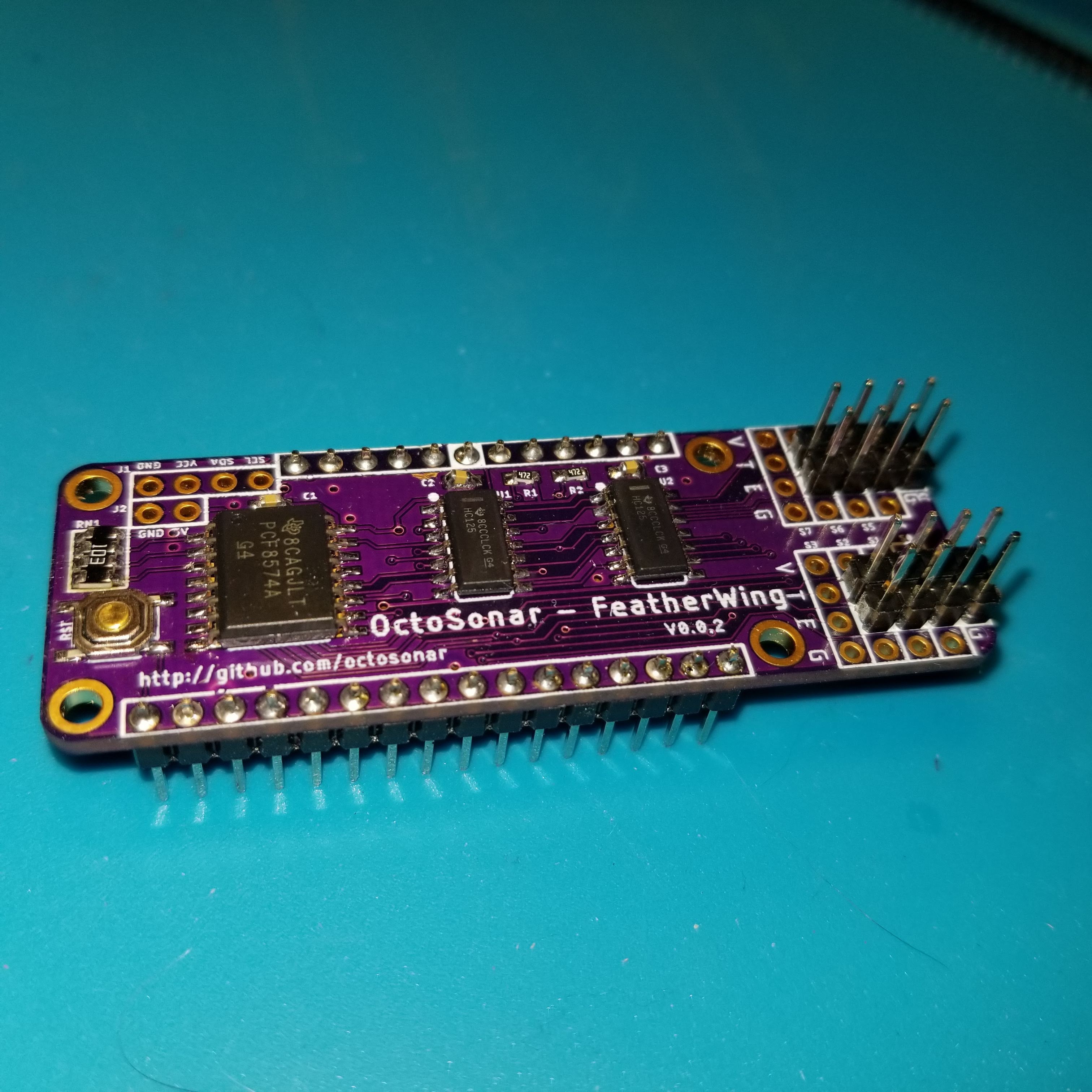
  • Featherwing Format

    Alastair Young05/10/2022 at 18:59 0 comments

    SOme time ago I updated the design to featherwing format. It is still usable via a cable connection, but now it can also be plugged directly onto a Feather format controller.

    I also turned the camera on while making the most recent batch. While I do need to work on my camera skills it does show the end to end process of making these boards along with testing and packing.


  • V3?

    Alastair Young11/14/2019 at 03:13 0 comments

    So I'm in the process of redesigning the boards for the featherwing footprint. This should make them easier to use for feather adherents, as well as smaller in general. Keeping the ability to be wired standalone. These are in separate projects for entry into the current hackaday contest.

    This has got my brain clicking that what I should really do is to put an ATTiny on the boards and run the code locally. This will make it much easier to use with non-Arduino platforms - save me learning how to do hardware interrupts on RPi for instance.

    An ATTiny85 would not have enough pins even to drive a shift register and I2C and retain the reset pin so I'm thinking ATTiny841. On the 8 port board that has enough pins to drive the sensors directly, and it will fit in where the PCF8574 is on the feather footprint. For the 8 port I could either go with a more-pins ATTiny or go with shift registers and an ATTiny 841. As the sensor headers and the tristate buffers are all on the featherwing added footprint, there is lots of space to do that within the new form factor. And using shift registers allows for daisy chaining for people that want to use silly quantities of sensors. (like 16 isn't silly enough?)

    Will have to bit-bang the shift register as the SPI overlaps the I2C on all the Tiny chips I'm looking at.

    Naming is problematic 

    maybe Octosonar3/8 and Octosonar 3/16 ?

  • Archived V1 instructions

    Alastair Young09/16/2018 at 21:55 0 comments

    Archiving the original V1 board and no-board prototype instructions here.

    THIS IS NOT CURRENT

    Hardware

    The minimum setup to use this usefully requires

    • a PCF8574 or PCF8574A IC
    • two HC-SR04 sensors
    • two NPN transistors and some resistors to make a NOR gate
    • example sketch SonarI2Cv2

    basic breadboard testSoftware

    If you are using version 1.6.2 or later of the Arduino software (IDE), you can use the Library Manager to install this library:

    1. In the Arduino IDE, open the "Sketch" menu, select "Include Library", then "Manage Libraries...".
    2. Search for "SonarI2C".
    3. Click the SonarI2C entry in the list.
    4. Click "Install".

    If this does not work, you can manually install the library:

    1. Download the latest release archive from GitHub and decompress it.
    2. Rename the folder "SonarI2C-master" to "SonarI2C".
    3. Move the "SonarI2C" folder into the "libraries" directory inside your Arduino sketchbook directory. You can view your sketchbook location by opening the "File" menu and selecting "Preferences" in the Arduino IDE. If there is not already a "libraries" folder in that location, you should make the folder yourself.
    4. After installing the library, restart the Arduino IDE.

    (note - the above instructions adapted from a Pololu readme)

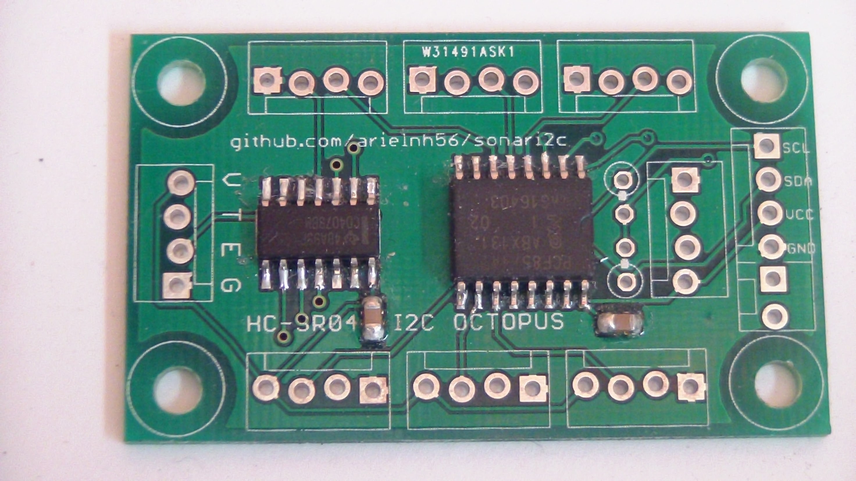
    HC-SR04 I2C Octopus "octosonar"

    There was enough interest in these that I made up a small batch to sell on Tindie.

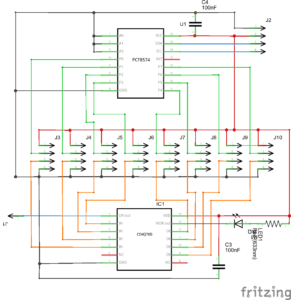
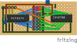
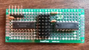
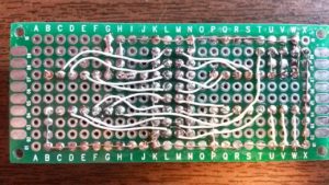
    To test these without the headers attached, I made up a test-bed on an Arduino proto-shield. This tests all the power pins (the green LEDs), checks the outputs from the PCF8574A and feeds signals into the CD4078 and verifies the output.

    There is a minor error on these boards in that the silkscreen "Name" layers are missing so it does not show what port is which. Refer to the image below.

    IMPORTANT: There are no pull-down resistors on the Echo inputs. Jumper any unused ports from E to G or you will get very erratic results.

    The 8 Port Prototype

    octalsonarshield_schem
    octalsonarshield_bb
    20160424_153047
    20160424_153028

    Download the current SonarI2C library code on GitHub

    HC-SR04 I2C Octopus "octosonar"

    There was enough interest in these that I made up a small batch to sell on Tindie.

    To test these without the headers attached, I made up a test-bed on an Arduino proto-shield. This tests all the power pins (the green LEDs), checks the outputs from the PCF8574A and feeds signals into the CD4078 and verifies the output.

    There is a minor error on these boards in that the silkscreen "Name" layers are missing so it does not show what port is which. Refer to the image below.

    IMPORTANT: There are no pull-down resistors on the Echo inputs. Jumper any unused ports from E to G or you will get very erratic results.


  • OctoSonarX2 and Trimounts now shipping

    Alastair Young10/03/2017 at 04:56 0 comments

    The first batch of the OctoSonarX2 units are built, tested and ready to ship.

    https://www.tindie.com/products/10614/

    The Trimounts are also sorted into little baggies in sets of four

    https://www.tindie.com/products/10615/

  • OctoSonar 1.1.0 code release

    Alastair Young07/27/2017 at 05:53 0 comments

    https://github.com/arielnh56/OctoSonar/releases

    1.1.0 adds support for the 16 port OctoSonarX2

  • HC-SR04 Trimount and OctosonarX2 demo video

    Alastair Young07/26/2017 at 06:46 0 comments

    Trimounts and OctosonarX2 demo video

  • The OctoSonarX2 Board Works!

    Alastair Young07/23/2017 at 03:27 0 comments

    I needed to tweak the software a bit - an update release is on the way. Fun with derived C++ classes!

    Anyhoo the thing works with 12 units on 4 trimounts. I'll pick up a new piece of acrylic tomorrow to mount this all on.

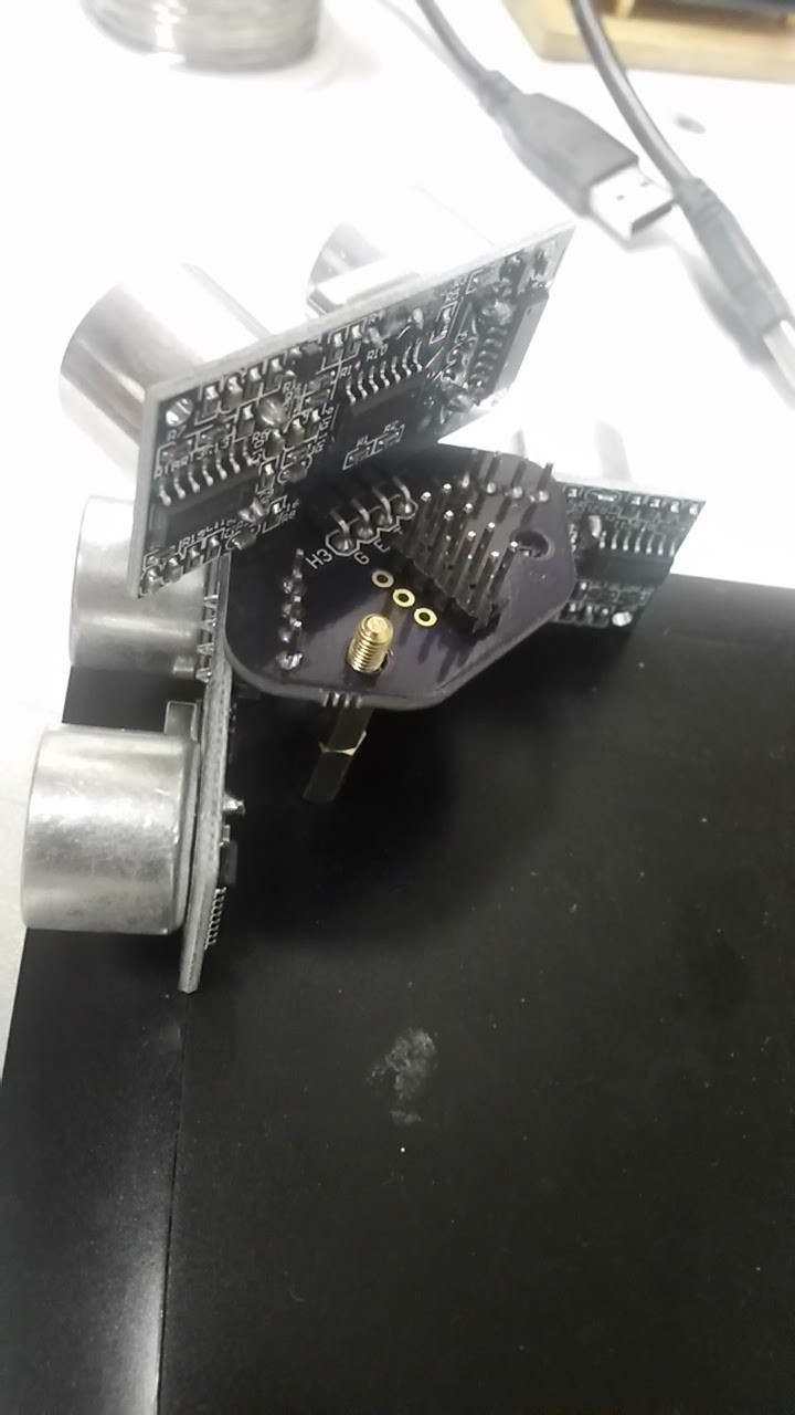
  • Trimount HC-SR04 brackets work

    Alastair Young07/21/2017 at 17:13 0 comments

    But need a little tweaking. The diagonal unit should be pulled back a little, to keep the unit within the same overhang as the rectilinear ones, and the corner hole needs a little more clearance.

  • Widening the range

    Alastair Young07/06/2017 at 05:32 0 comments

    The v2 board is faster with normal HC-SR04, cutting off the 200ms no-echo units at 50ms, and doing the same with the bad units that never come back, but that doesn't address the blind spots at the corner of the robot or the hassle of handcrafting mounting brackets.

    The code does support multiple boards but that's klunky.

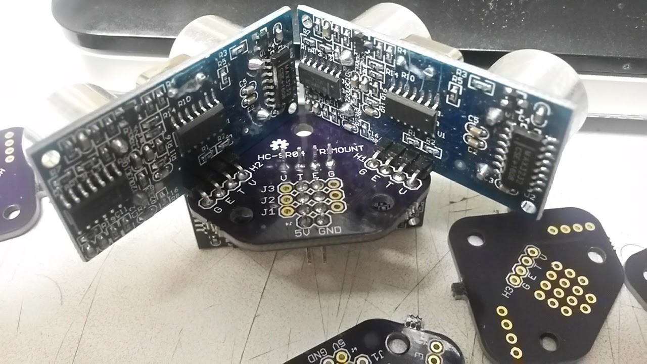
    I just fired off prototype designs to OSHPark for a 16 port board based on the PCF8575 and a little board to mount 3 HC-SR04 on each corner - with two at right angles on one side and a third at 45 degrees on the other. The idea is to mount it on standoffs.

    The extra V and G pins on the connector blocks should allow the three sensors to be run from 2 4-pin cables by inserting them at right angles.

    Any interest? Comments welcome!

  • v2.1 boards are built

    Alastair Young06/26/2017 at 01:11 0 comments

    The new boards are built and a very pretty blue they are.

    I mounted one up on the greenbot and it works as designed.

    I made up a test jig and an arduino sketch to wiggle all the pins and watch them from another PCF8574.

    I did run into some timing issues reading from the jig, but those went away when I turned off the Serial.println commentary. I'm thinking there is some weird interaction between the Wire and Serial libraries.


    Pictures in the gallery

View all 14 project logs

  • 1
    How It Works

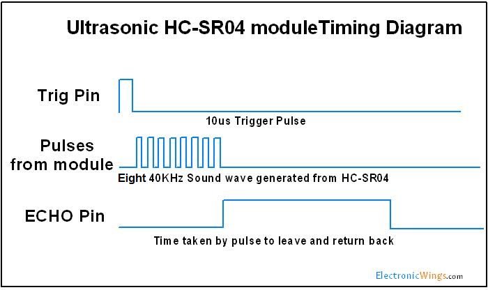
    The HC-SR04 ultrasonic sensor principles of operation are well documented on the internet. A good example is at ElecronicWings

    Below is their diagram of how it works.

    The Octosonar takes advantage of something that is not clear from this diagram. The 10us trigger pulse length is a minimum value. The trigger is actually on the falling edge (high to low transition). The sensor does not care if you keep TRIG high for much, much longer than 10us.

    The Octosonar keeps the TRIG pin high when the sensor is not in use, and low when it is in use - by default 50ms "low" and 350ms "high" (750ms "high" on the OctosonarX2). It gives each sensor 50ms "low" to take its measurement and also uses that "low" signal to enable a dedicated tri-state buffer to pass the ECHO pin signal to a hardware interrupt pin on the Arduino. 

    The TRIG pins are driven by a pin-expander chip on the I2C bus, with each active pin being made "low" in rotation. While I2C does not give good enough timing accuracy for echo measurement it works fine for this selection rotation function. Timing is taken by hardware interrupt routines, so the start and end of the ECHO pulse can be measured accurately, even if your Arduino code was doing something else at the time. 

    The results are stored away for your code to retrieve later when it looks for it.

  • 2
    Software Installation

    If you are using version 1.6.2 or later of the Arduino software (IDE), you can use the Library Manager to install this library:

    1. In the Arduino IDE, open the "Sketch" menu, select "Include Library", then "Manage Libraries...".
    2. Search for "Octosonar".
    3. Click the Octosonar entry in the list.
    4. Click "Install".

    If this does not work, you can manually install the library:

    1. Download the latest release archive from GitHub and decompress it.
    2. Rename the folder "Octosonar-1.2.0" to "Octosonar".
    3. Move the "Octosonar" folder into the "libraries" directory inside your Arduino sketchbook directory. You can view your sketchbook location by opening the "File" menu and selecting "Preferences" in the Arduino IDE. If there is not already a "libraries" folder in that location, you should make the folder yourself.
    4. After installing the library, restart the Arduino IDE.

    (note - the above instructions adapted from a Pololu readme)

  • 3
    Wiring Up the Octosonar

    The connections on the Octosonar are clearly labelled. I'll try and run up a wiring diagram later, but for now the following list of connections should get you there.

    To connect to Arduino

    Octosonar PinUno Pin
     Default
    Description
    5V5V5V supply for the HC-SR04 sensors. If you have a 5V Arduino (e.g. Uno) you can skip this connection and bridge the V1 solder jumper on the back to use the VCC suply for this purpose.
    INTD2The hardware interrupt pin you select in your code. 
    SCLA5The I2C SCL pin or your controller.
    SDAA4The I2C SDA pin or your controller.
    VCC5VThe voltage power used by your controller. This will be either 5V (Arduino Uno) or 3.3V (Raspberry Pi, Arduino Pro 328 - 3.3V etc).
    IMPORTANT: if you have a 3.3V controller, DO NOT SOLDER V1
    GNDGNDGround

    Solder Jumpers on the back A0, A1, A2 allow you to change the I2C address from the default 0x38

    The V1  solder jumper is used to connect the VCC and 5V paths together - which saves you a wire if VCC and 5V are the same thing on your controller.

    To connect to HC-SR04, the eight connectors are marked VTEG matching the pins on the HC-SR04. If you are not using all the ports you can disable the inactive ports in software which will give more frequent polling of the active sensors. The ports are numbered S0 thru S7 (S was for "sensor") and are spaced to allow molex locking headers to be used.

View all 6 instructions

Enjoy this project?

Share

Discussions

daniele bordignon wrote 08/24/2019 at 22:18 point

What can I do if I run on node.js?

  Are you sure? yes | no

Alastair Young wrote 08/26/2019 at 20:44 point

The code I support is written for Arduino using the C/C++ code that comes with the Arduino IDE.

The device is compatible (depending on V1 solder jumper) with 3.3V or 5V logic, however a 5V supply is needed for the sensors.

In theory therefore any controller running on 3.3V and 5V will work, if the software is written for it. 

The code is open source, feel free to translate it to any language or platform you like, or write your own from scratch.

Or run a slave arduino (or attiny) to drive the device using my code, and have your node.js system talk to it. There was a similar product on Tindie with the microcontroller built in. Seems to be gone now.

see https://theotherandygrove.com/octasonic/ for info on that

  Are you sure? yes | no

stoduk wrote 02/26/2017 at 12:33 point

Did you consider using US-100 ultrasonic sensors?  

They are superior to HC-SR04 (or other trigger/echo sensors) because they do the time of flight calculations on board (plus have temperature compensation, which is a smaller increase in accuracy).  eg. for a 697mm measurement I found trigger/echo measurements would overestimate by 25mm and would vary by 6mm.  US-100 gave a measurement that exactly matched my tape measure and returned the same value every time (to mm accuracy).

Using this might make it easier for you to move your robot parallel to a wall using only a single device with a tuned PID - the variability in the results you get from HC-SR04 would likely make that impossible.

See https://github.com/stoduk/PingSerial/ if you want more details.

  Are you sure? yes | no

Alastair Young wrote 02/26/2017 at 20:06 point

I'm not familiar with those, however a quick google suggests that they are very similar albeit a bit more accurate and temperature compensated.

https://arduibots.wordpress.com/2013/10/14/comparison-of-ultrasonic-sensors-us-100-and-hc-sr04/

They *don't* seem to do time of flight calculations any different from the HC-SR04, (the controller has to measure the returned pulse length in the same manner) so can you verify where you saw that?

I would think they could be drop-in replacements for the HC-SR04.

The tuned-pid one-sensor approach only works if your robot is travelling forwards so it can tell if it is getting closer as it goes. I want the ability to line up to the wall while not rolling forwards. To do that I need two sensors on each side, spaced wide apart. For this it's more important that they give the same value as each other for the same distance than they give a number that matches a ruler.

Also I'm a cheapskate :-)

  Are you sure? yes | no

Alastair Young wrote 02/27/2017 at 07:57 point

https://arduibots.wordpress.com/2014/10/12/us-100-ultrasonic-sensor-in-serial-mode/

Oh, that is interesting. I think my specific hardware solution is only going to work with the trig-echo mode, which matches the SR04. Unless it were possible to send the 9600 baud request messages by flapping the pin on the expander to fake 9600 baud. That's complicated and a lot of work for the Arduino which probably has other things to think about, but a fascinating idea.

  Are you sure? yes | no

stoduk wrote 02/27/2017 at 09:18 point

HC-SR04 and US101 do the same thing - send pulse, wait for echo, calculate distance based on how long the echo takes to come back.  The difference is in what calculates the distance (sensor vs. microcontroller) and how the communication works (timing magic vs. TTL serial).

With the HC-SR04 your MC sends a pulse (with some timing magic) then wait for the echo pin to go high, and from the elapsed time the MC calculates the distance.  With the US-100 your MC sends a TTL serial message to trigger the measurement, and then gets a TTL serial response with the distance.

The important bit here is where the elapsed time measurement is being done.  With US-100 it is done on the sensor itself, so is as accurate as we can get (plus we get temperature compensation too, which affects accuracy).  With HC-SR04 and similar you rely on the MC to measure the difference - and this potential latency in the MC noticing the echo pulse can cause both inaccuracy  (value calculated is greater than it actually is) and imprecision (measuring a fixed distance doesn't give a fixed result, due to the unpredictable latency).

US-100 are cheap enough that, for me, their improved accuracy and precision is well worth it.  Currently US-100  cost £2.22/sensor vs. £0.99 for HC-SR04, so the difference in absolute terms is small.

I'm not sure I understand how multiple sensors help you line up to a wall better than a single (accurate and precise) sensor.  Two sensors are needed to let you know if you are parallel certainly, but if you aren't parallel and want to get there then you need to move - at which point either one or two sensor setups should do the job.  I'd bet improving your accuracy/precision would help a lot with that, hint hint :)

Anyway, your design certainly looks good, just suggesting some alternatives.  I imagine you could do it with a handful of 555 ICs but I haven't touched them for two decades, so I'm not the one to tell you how to do that.

  Are you sure? yes | no

Alastair Young wrote 02/27/2017 at 23:32 point

my initial google found a reference to the trig-echo mode on the SR-100. It was later I spotted the TTL/Serial mode. I agree that doing the time calculations in the module is preferred, as it saves the controller doing it and avoids timing conflicts on the controller.  I think the Ping))) does things on-board too, but they are way expensive. So I do like that, but how would one address the issue of talking to lots of them? Those 74HC4051 analog MUX chips mentioned by the other guys would work, I think.

Take a look at my sonari2c library. I think I'm taking a different approach from the other libs out there in that I am using short hardware interrupt routines to record the timestamps of the start and end points of the echo pulse in microseconds. Parked next to a wall I get *very* stable results. As long as you are careful with your code, (e.g. don't write any other interrupt routines that run long) you should be able to maintain this accuracy. 

My thinking is that having sensors at the end of each side of the bot will help in multiple ways while negotiating tight spaces. 

Specifically I'm thinking about the Robogames Firefighting Challenge. 

http://robogames.net/rules/fire-fighting.php

With that, knowing when my nose is next to an opening and my rear isn't will be useful, as well as other things like my front left is up against a wall but my front right isn't etc. Previous attempt had one front sensor and one on each side, and there really wasn't enough data to navigate intelligently.

  Are you sure? yes | no

K.C. Lee wrote 02/22/2017 at 02:38 point

You could do the same with two 74HC4051 analog MUX to multiplex the 2 signals to 8 ultrasonic modules.  Just run 3 GPIO to select the address and no need for I2C.

  Are you sure? yes | no

Ted Yapo wrote 02/22/2017 at 02:51 point

would you choose the analog mux over a 74HC138/74HC151 pair because you can use two of the same 74HC4051 instead of having two different parts, or is there more to it?

  Are you sure? yes | no

K.C. Lee wrote 02/22/2017 at 02:56 point

Using the same part. Also easier for someone to understand how it is going to work. 

I would just use a CPLD myself, but then again I have already reverse engineered the modules and integrated it with ARM chip.

  Are you sure? yes | no

K.C. Lee wrote 02/22/2017 at 03:49 point

BTW 74HC138 won't work because the trigger signal is active high and its output is active low.  74HC238 on the other hand is the right part for this application

I don't have to worry about details like that with an analog MUX.

  Are you sure? yes | no

Ted Yapo wrote 02/22/2017 at 03:28 point

What CPLD would you recommend as a start.  I'm still stuck in the GAL16V8 era :-)

  Are you sure? yes | no

K.C. Lee wrote 02/22/2017 at 03:37 point

Any of the smallest CPLD would do. They are around $1 range with 32-36 macrocells.  e.g. XC9536XL, EPM3032, LC4032.

  Are you sure? yes | no

Ted Yapo wrote 02/22/2017 at 04:16 point

Can't use the 74HC138?  Hmm. Is the module not edge-triggered? Can't you just pull the trigger line low then back high to initiate a ping, while the inactive trigger lines all stay high?  or does that make them ping continuously or something equally bad?


But you're right, I always forget the active low outputs of the '138 :-)

  Are you sure? yes | no

Alastair Young wrote 02/22/2017 at 05:59 point
I had to look this up as I confess I'm not familiar with those. Looked up the datasheet and that would use 4 more GPIO pins on my robot build. 3 for addressing and one to send the pulse. I'm not counting the I2C pins as I'm already using them to talk to the display and to pass packet data instructions to the embedded atmega328 in the motor driver card. I'm a self confessed pin-miser with an I2C fetish and I don't know yet what I might want to add to those pins. The easiest way to put an LCD on an and Arduino based bot these days is a 1602 with a pre-installed I2C backpack, so they are very often already active in I2C use.

Using those chips would save a little cash - maybe 60c on parts per unit, and they do come in a narrower package than the PCF8574. Also running the echoes through one would protect from any rogue inputs from the sensors or floating inputs on open ports, though that isn't a problem I've seen yet (open ports on the 4078 need to be grounded.)

The trigger for the HC-SR04 is the falling edge of the signal on the trigger line, and the echo pulse is positive, with a duration equal to the round trip of the ultrasound. The trigger signal is not time critical, so I2C is no disadvantage. For accurate timing the echo signal somehow needs to come into a pin with an interrupt set on the rising and falling edges.

Another aspect of my design that I like is that I can daisy-chain another of these on the same interrupt pin and add another 7 units. I'm planning to add 4 - one on each corner where the robot has blind spots. Currently if it is at 45 degrees to a wall it can't see it.

Thanks for this comment, now I have a whole new breed of chips to learn about! 

CPLDs are probably beyond me at this point :-)

  Are you sure? yes | no

K.C. Lee wrote 02/22/2017 at 11:35 point

Up till the I2C patent expired (years ago), Philips (NXP) was still suing anyone and everyone for money.  So not something I would like to support if I have better alternatives based on principle.

http://www.eetimes.com/document.asp?doc_id=1182191

>Philips Corp. today announced it has filed patent infringement suits against eight more companies accused of violating its technology rights in I2C bus interconnects on semiconductors. The latest round of suits follows similar cases filed against six U.S. chip makers one year ago.

  Are you sure? yes | no

Ted Yapo wrote 02/22/2017 at 15:54 point

Of course, you know more about the constrains and goals of your own project than we do :-) 

I think this kind of discussion is the sport of hackaday.io - I'm expecting someone to chime in with an NE555 comment, although that may be more hackaday.com-ish

  Are you sure? yes | no

Alastair Young wrote 02/22/2017 at 17:43 point

The lawsuit things seems to be against semiconductor manufacturers, and most of the chips I am using are genuine Philips (NXP) chips (though I also used a few  Texas Instruments) chips. This is tiny scale hobby stuff. And that article was from 2001.... Not worried.

  Are you sure? yes | no

K.C. Lee wrote 02/22/2017 at 19:53 point

It has expired, but I do not agree with their practices. Kind of a sore point for the Open Source thing I think. Thus I said about "not using it based on principle.".

  Are you sure? yes | no

Alastair Young wrote 02/21/2017 at 04:31 point

The robot is a work in progress with me learning as I go. It is a step up from the predecessor which had only 3 sensors, one at the front and one on each side near the front. I found with that to follow along a wall you had to move to figure out your angle i.e. "I am getting closer, I need to turn away". This is not very helpful if there is a wall up ahead. So I figured if I had two on each side mounted straight out, I could know not only how far, but at what angle a wall is - without moving. I'd also get an idea of whether my butt is clear of the opening before turning. This works as intended, but showed up the next challenge - blind spots on the corners.

Let me think about your idea - every 45 degrees. Logically that would be one on each side and one on each corner. The sonars can see reliably 15 degrees on either side of center, and dodgily up to 22.5 degrees. see http://www.instructables.com/id/Arduino-based-Distance-Measure-Box/?ALLSTEPS

At a 45 degree spacing you would pretty much be blind-spot free but none of them would be able to see the same wall at the same time, and I'd lose the parallax that allows me to statically adjust relative to flat surfaces.

However, the next step in the plan is to add 4 more sensors at 45 degrees at the corners to cover the blind spots, pretty much like you suggest. I'll just watch for these to have a range lower than the sensors on either side. When that happens I'll rotate out of the blind spot.

The Octosonar echoes can be daisy-chained (they are OR logic gates) so with two of them I can still run 15 sensors on 1 interrupt pin. I breadboarded this out early on.  The challenge is mounting brackets. The more sensors you ping in rotation the longer it takes : 50ms each - 12 would take 0.6s - a long time for a moving robot. That's why the library lets you turn off the ones you care less about, like the ones at the back when moving forwards.

  Are you sure? yes | no

davedarko wrote 02/21/2017 at 07:25 point

it wouldn't hurt to try :) seems like you still know you're angled to a wall when the side gets closer/ shorter ranges, so it would be possible to counter act that angle like a line follower does. But I'm just assuming here.. 

  Are you sure? yes | no

Alastair Young wrote 02/21/2017 at 07:32 point

I want to know the angle to the wall without moving. The firefighter maze is a very confined space. Need the parallax of two sensors. That's why we have two eyes pointing forwards. I think 12 will be enough :-)

  Are you sure? yes | no

scamianbas wrote 06/18/2017 at 14:47 point

Hi, can you please publish a schematic of daisy-chain configuration ? Thanks

  Are you sure? yes | no

davedarko wrote 02/21/2017 at 01:15 point

I just saw the video of the robot and have one question: why don't you angle the 8 sonar modules on your robot in 45 degrees? Seems like the arrangement of them isn't optimal to show the full capabilities of this project. 

I like the idea of the project itself :) thank you for sharing.

  Are you sure? yes | no

Similar Projects

Does this project spark your interest?

Become a member to follow this project and never miss any updates