EjaadTech
-
the Sensors
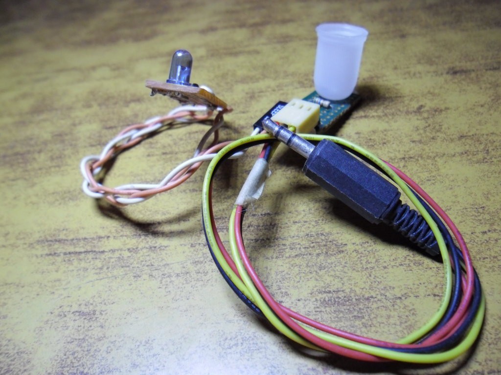
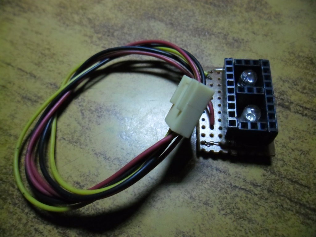
07/22/2014 at 07:12 • 0 commentsHere are the 2 sensors I designed for this tachometer,
1 is a reflective type, meaning it will detect movement based on the reflection of light and the other is a pass through, the counting is done when light is CUT.
![]()
![]()
-
Design Phase and PCB
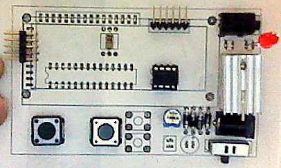
07/22/2014 at 07:00 • 0 commentsThe Tachometer needed to be small, portable, and should be extensible, so many designs were made and finally the one agreed upon was first tested on a cardboard cutout.
![]()
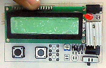
![]() On top is the ISP connector for programming, on the left are the extra pins left, the sensors input were put with a 3.5mm audio jack female connector and the 2 ICs, the Opamp and the ATMEGA8 were concealed beneath the LCD.
On top is the ISP connector for programming, on the left are the extra pins left, the sensors input were put with a 3.5mm audio jack female connector and the 2 ICs, the Opamp and the ATMEGA8 were concealed beneath the LCD.I designed the PCB with big traces and some jumpers as I was just learning to make PCBs back then.. :) the final outcome:
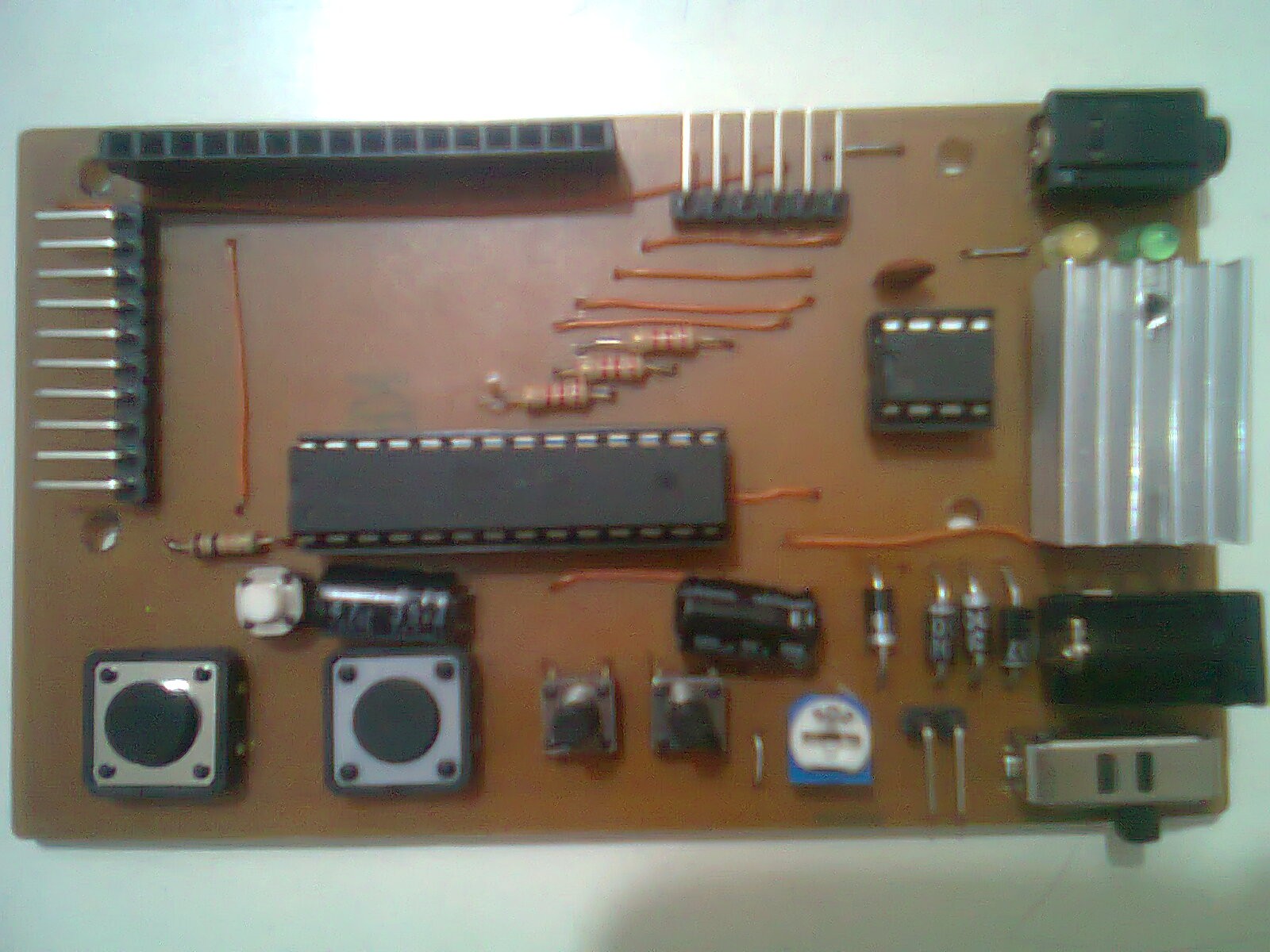
![]()
without the LCD
![]()
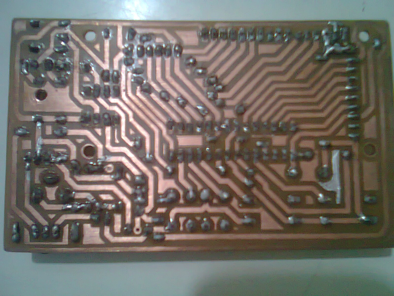
The bottom Copper side
![]()
-
Breadboarding
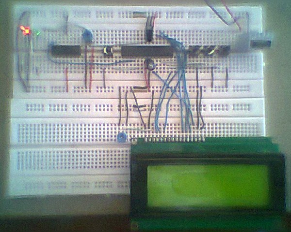
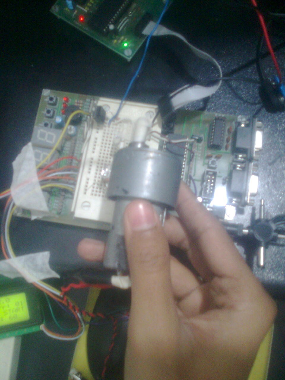
07/22/2014 at 06:23 • 0 commentsthe project started on a small breadboard on an AVR Dev board I had which used AVR ATMEGA32
then moved to a proper breadboard with ATMEGA8 before finally going to the PCB..
![]()
![]()
![]()
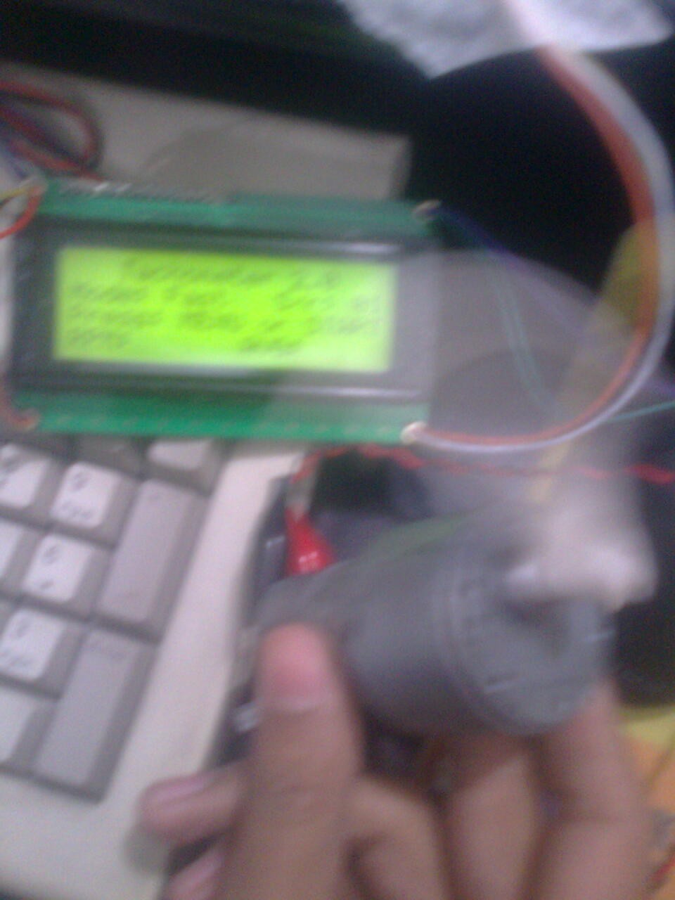
the first test with a tape on a motor and looking at the LCD for results..
![]() the first simplest sensor, a pass-through...
the first simplest sensor, a pass-through...![]()
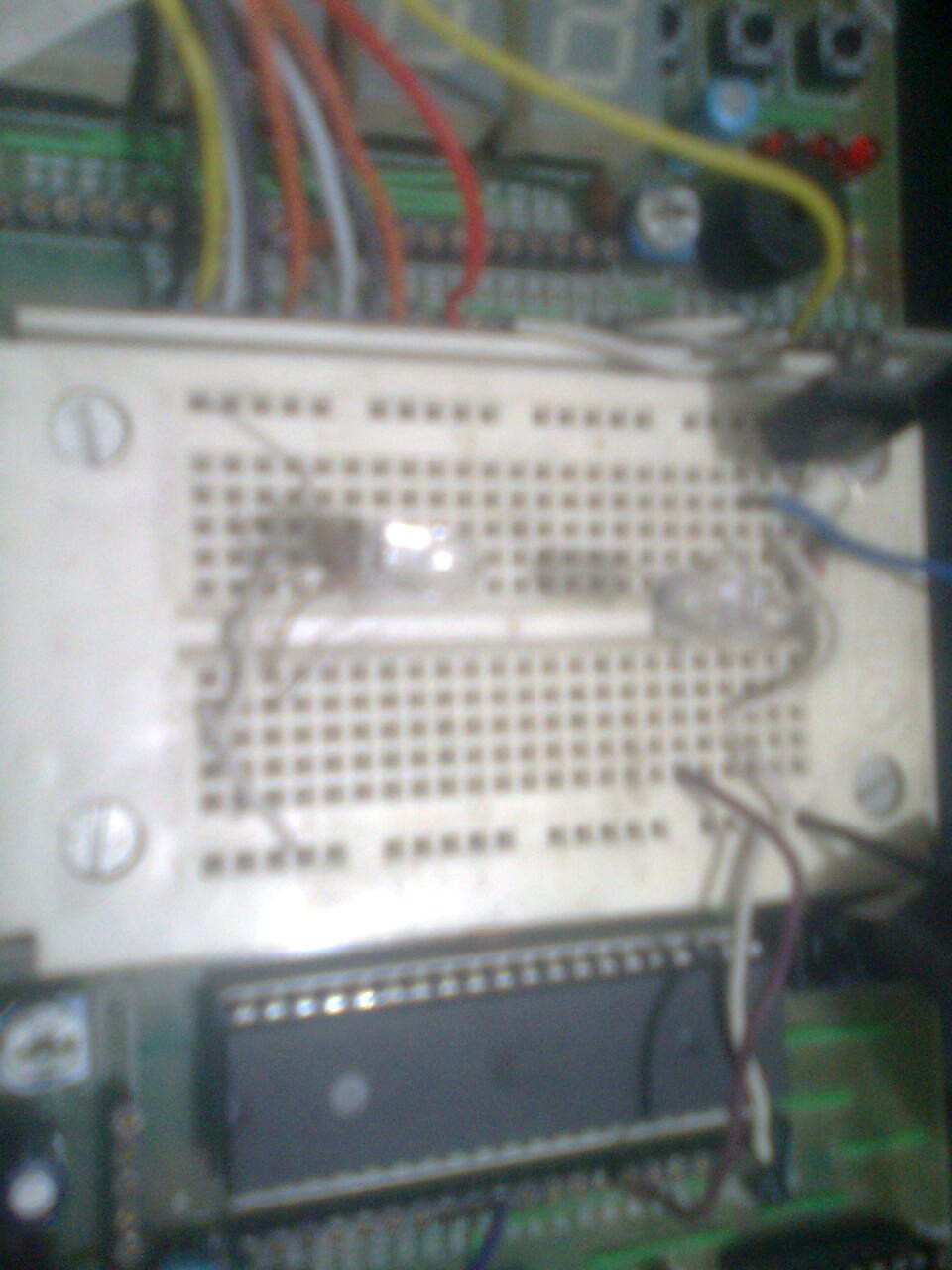
the final breadboard, the images are old and from a very cheap camera.. :) at the right is the 7805 with a heatsink, then the 3 buttons for settings etc, then the AVR ATMEGA8 and finally the OPamp IC so I dont need to do ADC on the sensor, working as a comparator, the opamp provides a simple square wave out to the AVR, which is put on the interrupt pin, as I recall..
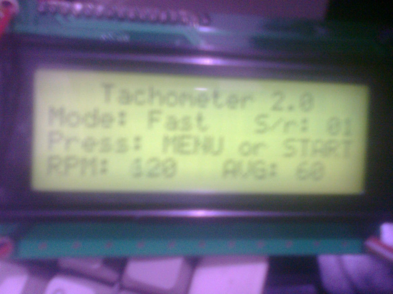
Tachtastic - a fantastic Tachometer
I know, a cheesy name - an AVR ATMega8 tachometer, with external sensors and a good design experience.
 On top is the ISP connector for programming, on the left are the extra pins left, the sensors input were put with a 3.5mm audio jack female connector and the 2 ICs, the Opamp and the ATMEGA8 were concealed beneath the LCD.
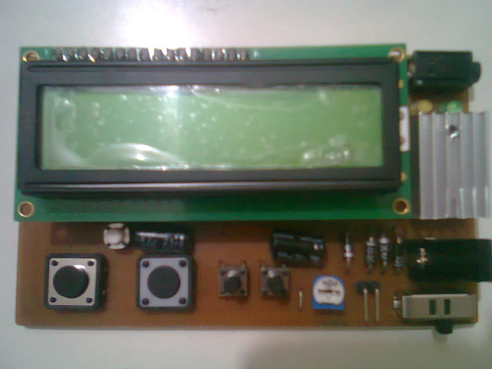
 the first simplest sensor, a pass-through...