Paul Crouch
-
Minimal UPS and a plan
05/22/2020 at 19:23 • 0 commentsI've finally got back to the UPS (now as its own project, mUPS), so hoping to have it working soon so I can work on the robot again.
I have been thinking about motors, controllers, gearboxes and leg mechanisms in recent weeks and I am considering going back to the original 3D printed head design, for various reasons. I do have a plan. A loose, ever-changing plan.
-
Raspberry Pi UPS with safe shutdown
04/10/2019 at 23:40 • 0 commentsIt looks like I might finally have a functioning UPS. I say finally because it's taken way longer than planned due to both "technical difficulties" and resource availability. We're approaching exam season so my computer and bench are hijacked daily by the youngest of my offspring and I can't complain about that. This does, however, mean investigation of any technical difficulties spans weeks.
That's the excuses out of the way. Here's the short version of what happened:
- I needed a UPS for the Raspberry Pi to handle sudden power loss and prevent file corruption.
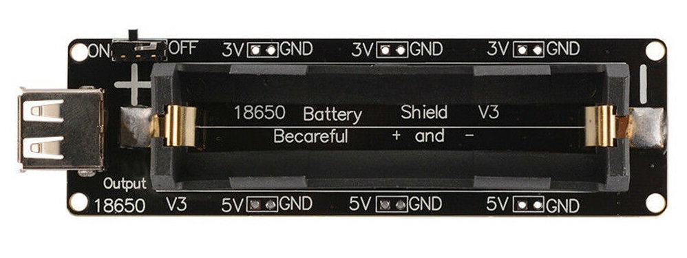
- The "Wemo 18650 Battery Shield" will output whilst taking power and it's cheap. I like cheap.

"Wemo 18650 Battery Shield" - The RPi can't be trusted to shut it's own power off so I looked for the smallest, cheapest Arduino-type board (to minimise faffing) to handle the delay-if-then logic. I got a couple of DigiSpark boards (clones as it turned out) and cobbled together the code and connections.
- Saw some odd behaviour, maybe the DigiSpark board isn't what I need.
- Worked around the issue, circuit and code seem to work on the bench until the RPi is actually connected (instead of manually simulating the I/O signals).
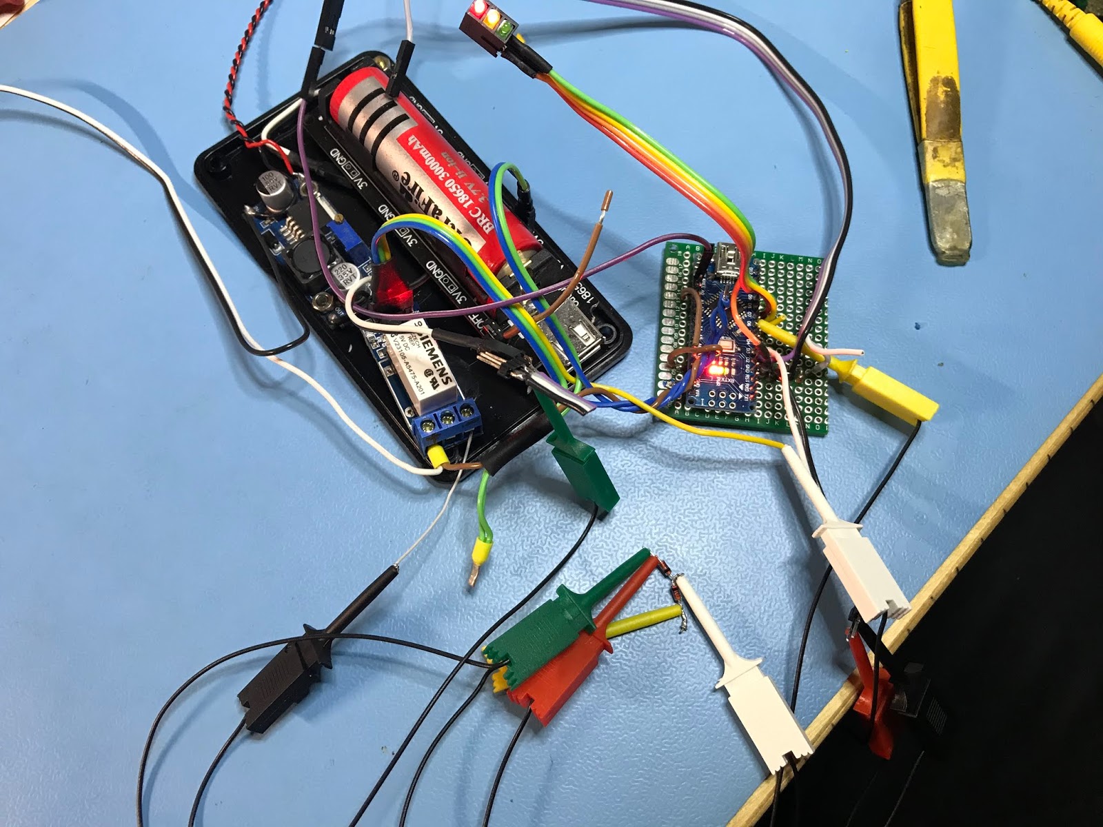
- (some time later) Sick of the DigiSpark; I switch to the trusty Nano, then add some traffic-light LEDs for indication and because I can.
- More odd behaviour; looks like back-feeding through the µC inputs. I should really disconnect the GND too.
- I transplant a small DPDT relay onto the opto-isolated "arduino" relay board and re-wire again to also break the GND this time.
Twenty-third-time lucky? - Dammit! Killed a Pi pin by forgetting 5V > 3V3. Moved to next GPIO and added a pot.div.
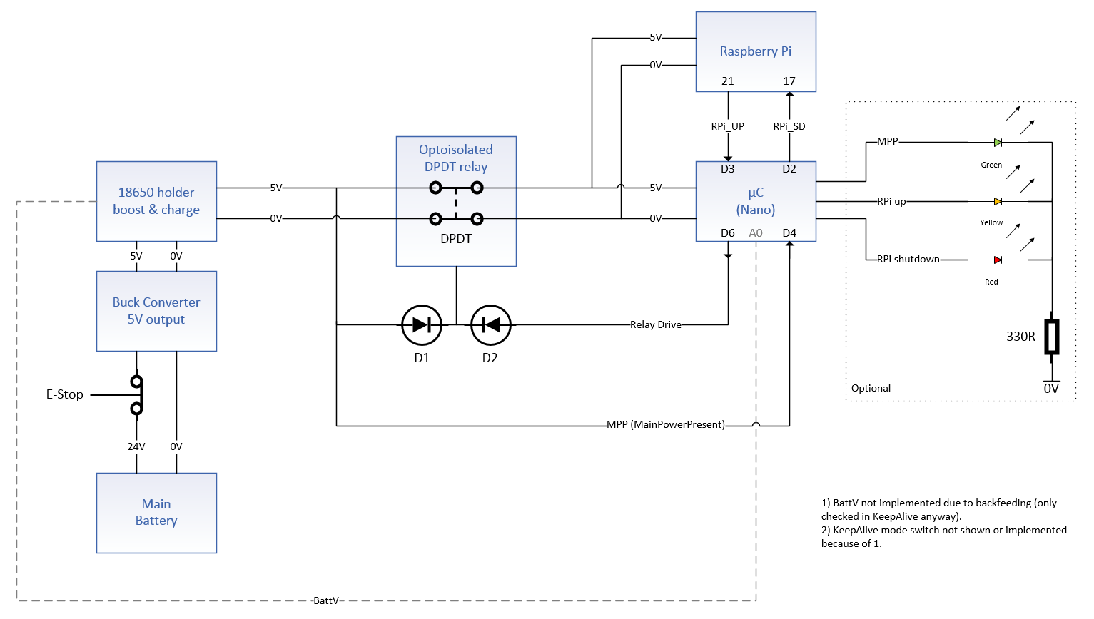
- Success!?! Tested the UPS with the RPi two or three times, mounted both in the head and moved on to power distribution but I'm waiting on some parts that got delayed in transit, so I'm using the time to write this. Below is the schematic I did a few days(?) ago.
UPS diagram (not showing GPIO potential divider!) Still here? Here's some notes:
A "18650 Shield" is used to maintain power to the Raspberry Pi upon removal of the main power (e-stop) allowing safe shutdown after main power-off. It uses GPIOs to trigger the RPi to shutdown, waits for the RPi to signal it is (almost) complete before opening a relay to disconnect the UPS power and prevent deep discharge of the battery.
Arduino
3 - RPi_UP (DI), RPi GPIO output - high after boot, low just before complete shutdown.
2 - RPi_SD (DO), RPi GPIO input - active-high to trigger shutdown of RPi (through pot.div; 5V >> 3V3).
A0 - ADC to 18650 battery, 4V - disconnect load from battery when voltage drops.
4 - Main Power present/not present (DI).
5 - Keep alive/immediate select switch (DI)*
6 - Relay (DO) - active-high opto-isolated (N.O. contacts). Opens to disconnect battery.
7 - Amber UP LED
8 - Red SD LED
9 - Green MPP LED*Mode selection input:
Keep alive = 0V - waits until battery is low before shutting down and disconnecting.
Keep alive = N.C. - immediate safe shutdown and disconnect.Raspberry Pi
RPi signals to UPS when it is up. UPS tells Pi to shutdown and waits for RPi_UP to go low before removing power.
RPi_UP=21 # GPIO output - high after boot, goes low a few seconds before complete shutdown.
RPi_SD=17 # GPIO input - active-high to trigger shutdown of RPi (through pot.div; 5V >> 3V3).I might revisit this, to fix the low battery check, but for now...
-
Logitech C920 camera pitch mount
01/08/2019 at 23:30 • 0 commentsLogitech C920 pitch mount - still needs painting. Waaayy back in December I modelled a pitch-roll camera mount for my Logitech C920 (autofocus, HD) to go on the head ring gear. Then I changed the approach and redesigned it... and again, then I dropped the roll axis as I was running in circles and it wasn't strictly necessary. Four or so printed iterations later I have a functioning active pitch control for the camera (yaw is taken care of by head rotation) allowing ±45° swing.
The 5th iteration (not including previous pitch-roll designs) and includes a remixed version of:
Logitech C920 Adapter for RaffoSan's Camera Arm by FelwatI modified the C920 mount so it now has a flat base for taping or welding. My remix can be found on Thingiverse: https://www.thingiverse.com/thing:3343134
I subsequently found what may have been a valid alternative:
Logitech C920 Universal Webcam Mount (Scews or 3M VHB) by ps915First time printing with PETG too. I'm waiting for some paint to arrive then I'll see how well it takes it. Methylene chloride seems to work nicely for welding and smoothing.
Nope What was I thinking?!? Almost Bad bearing retainer Tweaked and snapped 5th time lucky! -
Time flies...
01/08/2019 at 21:57 • 0 commentsNo major progress since my last post but I have done a few little bits here and there. I thought it might be a good idea to kind of copy-paste from some of my notes...
8 Nov 2018
I've managed to kill the RGB LEDs! Not sure how, but I was reassembling the head controller and wiring and couldn't get a response from them even using known-good code. I'm hoping it's just the first one in the string that is dead and I can cut it out. Need to revisit this in the future.
18 Nov 2018
Bought a little "NEO-6M" GPS module GY-GPS6MV2 for a crazy £3.89!
I wanted to try it out and it works as expected. I used http://freenmea.net/decoder to help make sense of the serial output.26 Nov 2018
CCW head rotation now working on negative target input from serial. Dev code did CW and CCW but couldn't start in CCW direction. Just needed tweaking.
I also added manual steering via a pot (and mode select switch), just for development purposes/fun.16 Dec 2018
Started work on power distribution; an aluminium box with busbars, fused outputs and, eventually, some sub-circuit isolator switches. Drilled large cable access hole and fitted rubber cable grommet. Mounted to main box-frame.
20 Dec 2018
I designed and printed an e-stop shroud to protect it from accidental bumps and as a guinea-pig for trying Frog tape on clean bed for first time. I've been using ABS slurry on the bed but my prints have been a bit iffy recently so wanted to experiment.
More tweaks to my camera pitch-roll mount with 9g servo models inserted. Need short ball-link rod ends to complete: on order from China (eBay).
Worked on another 3DP front panel design (again). Will include a 1602 orange on black LCD when it arrives from China. Couldn't find a 20x4 at a reasonable price, considering it's mostly for fun.
27 Dec 2018 - Printer maintenance and quick PETG trial
Cooling fan on printer PSU was very noisy and on its last-legs. Replaced fan and tightened-up all screws on printer body.
ABS 2cm test cube, 1mm wall at "normal" 0.15mm layer height:
- 235°C/100°C - had slight baggy corners at bottom, lumpy-snotty rear corner.
- 230°C/80°C + fan (but no duct) - better corners, no sagging.
- 230°C/80°C + fan & duct - as #2 but slightly more bottom warping (curl).
PETG 2cm test cube, 1mm wall at "normal" 0.15mm layer height:
- 215°C/70°C/fan - stock Cura PETG settings. Very good print, but bottom came away quite easily.
- 2. 230°C/80°C/fan - excellent print! Clean and strong.
I love PETG!
-
Ubuntu & ROS (Robot Operation System) on a RPi3B+
10/20/2018 at 17:39 • 0 commentsAfter reading up on different Linux distros (whoa, that's a rabbit-hole!), I installed and tried a few before settling on Ubuntu MATE. I chose it because it has a large community, lots of support, examples etc and will run on a Rasberry Pi. I preferred the MATE desktop over the standard Ubuntu one too. I installed Ubuntu MATE on an old netbook for development purposes, then ended up dual-booting with it on my old main laptop too, then of course set about installing it on the shiny-new RPi3B+ that I recently purchased...
At the time of writing, the RPi3B+ will not run most Linux distros. That's the "B+", the "B" is fine. The architecture of the two are different and the B+ will only run Raspbian out of the box, a fact that isn't immediately obvious until you start looking into it. I had assumed that I could get the latest Ubuntu image (Bionic 18.04) and install the lastest ROS distibution (Melodic).
Ubuntu MATE & ROS Kinetic on a Raspberry Pi 3B+? As I understand it; Ubuntu MATE (16.04) is available for RPi2 and RPi3 but not the B+ and ROS Kinetic is available for Ubuntu Xenial 16.04 on the "armhf" architecture (Pi), but not for Debian-armhf. The latest ROS Melodic only supports Ubuntu Bionic. Kinetic is supported until April 2021, so shouldn't be a problem, but there's no Xenial/16.04 image for the Raspberry Pi 3B+. Xenial's support ends April 2019, Bionic/18.04 ends April 2023. So Bionic for armhf would be the better choice, if it existed...
See https://droidbot07.blogspot.com/2018/10/ros-on-raspberry-pi-3b.html for details.
-
System architecture
10/19/2018 at 14:37 • 0 commentsWell, my cunning plan for load-bearing mounts seemed to like too much hard work. Instead I used M6 rivnuts on the bulkhead and strategically placed hex-socket pan-head bolts through the sensor-ring (base of head/camera shield) to secure the two together.
With the head removed again, I mounted the sensors and began to consider how best to wire them back to whichever processor I was going to use. It got me thinking a bit more about the system architecture overall; what did I plan to use where and how was it going to inter-connect? I scribbled several diagrams on paper before moving to the digital domain. Below is the latest iteration of my imagined system architecture for Droidbot. It is an incomplete overview only, something to help me avoid major snags.
Droidbot System Architecture With the larger system in mind I dug out my Raspberry Pi (2, I think) to get a better understanding of how it all works. I quickly concluded I should get the latest and greatest RPi3B+ if I wanted to do image processing and similar, so I ordered one.
7" 1200x600 touch-screen for RPi
While waiting for the 3B+ to come in, I again connected up the display I had bought (some time ago). It's a reasonably sized 7" HDMI display with a touch panel, it's very nice and works well.
Touch panel for robot operator station GUI As part of the UI, further down the line, I'd like to have a remote touch-screen GUI at the operator's station. This panel is intended for that and it seemed like it would be up to the task with the right hardware and software behind it.
Playing with the RPi led to a whole load of RPi/Linux/ROS fun...
-
Sensor mounting & camera shield painting
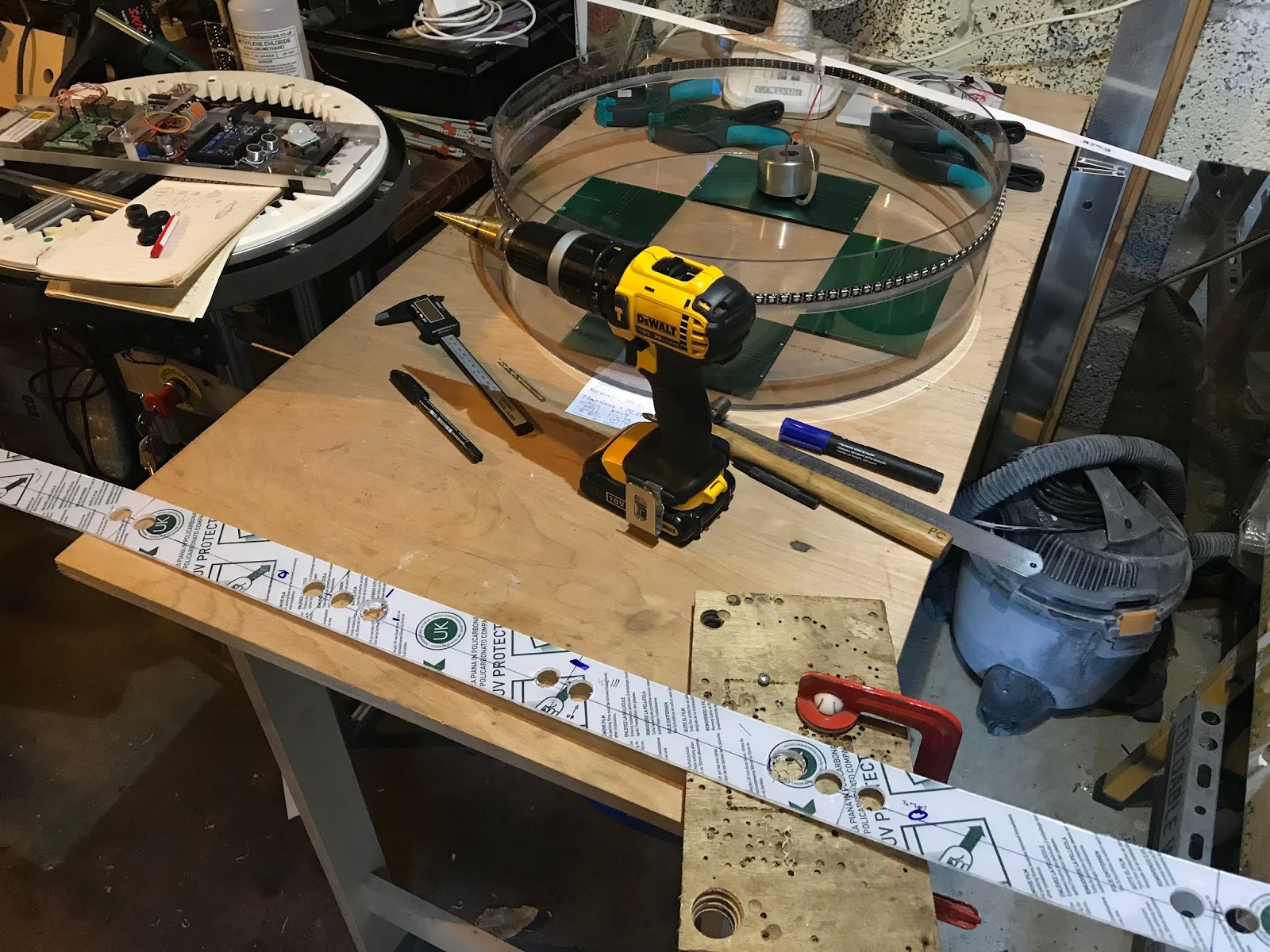
09/14/2018 at 07:24 • 2 commentsWith my week-in-the-sun over, I decided where I wanted to place the main sensors (after some research and experimentation with a couple of microwave Doppler modules) and made the appropriate holes in the polycarbonate strip that will become the sensor collar.
The RGB LED strip repeatedly fell off while the shield just sat there; the adhesive tape is clearly sub-standard but this did provide the perfect opportunity to paint where I needed without too much detailed masking. I peeled off the existing adhesive tape ready to replace it with some better stuff.
I clamped the polycarbonate strip in place, using the LED strip to set the spacing, then solvent-welded with methylene chloride again. It is good stuff.
I masked the shield with tape and newspaper before getting too carried away with the spray paint. I do it every time; too eager, too much paint, paint runs. Arse. I let it dry and sand it back. This time I go with 2 or 3 lighter coats as I should've done in the first place.
After masking and painting The result isn't perfect and I just noticed a small run that I'd missed. Oh well. It is what it is. Some more sealing and painting will be required on the top, but for now...
Next I cut-down some replacement adhesive tape and mounted the LEDs again and they seem to staying put this time.Mounted LEDs again A test fit was next on the agenda, to check how I was going to secure it and mark cut-outs to allow clearance for the rear of the sensors.
Test fit Rear sensor clearance was a rather hacky affair with shears and a knife. Load bearing fixings are now my concern, given that I wanted to be able to lift the whole robot by its head and there are no structural members protruding to the top (by design). It may not be possible in the end, but I have a cunning plan.
-
Polycarbonate head/camera shield
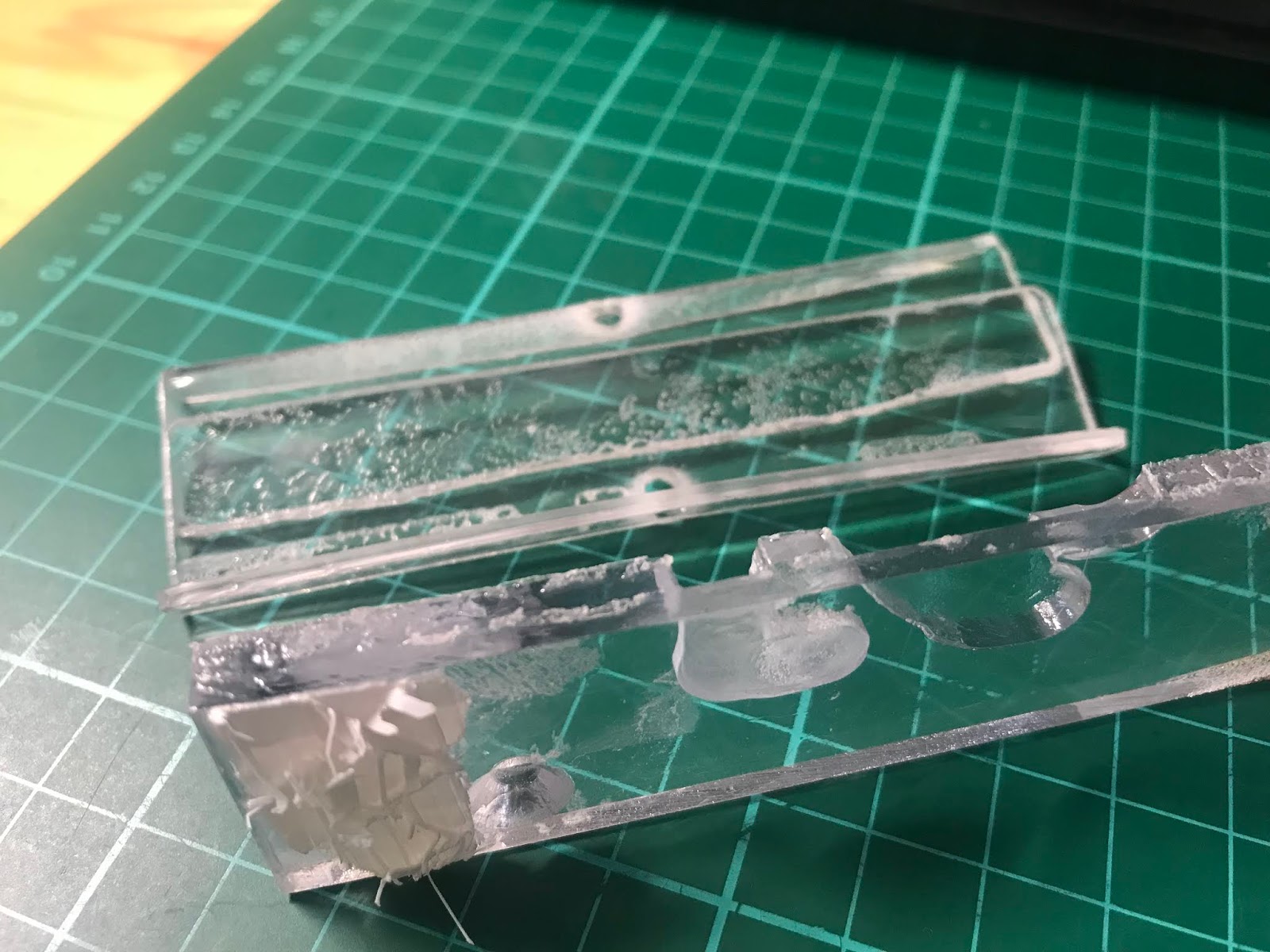
08/04/2018 at 19:34 • 0 commentsI'd read that polycarbonate can be welded with methylene chloride so I bought some (1 litre for less than £10 including the £5 shipping). I tested it on some scraps of polycarb and ABS and can say it solvent-welds polycarbonate and ABS extremely well. In the photo below, the top two pieces are well-and-truly fused and will not peel apart and the bottom piece, that was bonded to a failed ABS print, still has the skin of the print on it after some not-inconsiderable force was used to separate them.Solvent-weld polycarbonate and ABS with methylene chloride. Just to check; acetone barely touches polycarbonate and though it does fog it slightly it then fades. The polycarbonate strip in the photo below was dipped for a few seconds in each chemical. I would say methylene chloride is better than acetone for ABS too, certainly faster, though harder to spell :-)Acetone dip on top, methylene chloride on bottom. Assembly
I did a dry-fit of the parts and checked for any show-stoppers. I didn't want to ruin the material. It's not hugely expensive but it's not zero cost either and would take another week to come through.Dry-fit. The image below shows my intended plan. The main reasons for the overly complicated layering are because I didn't want the LED strip to sit proud of the main skin and I'd had an internal dimension to match for mounting.
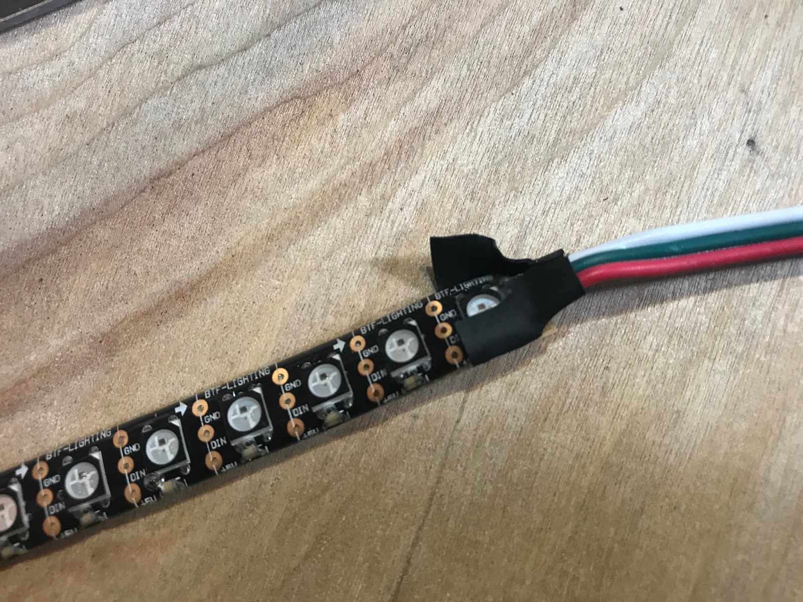
The plan. I just had to hope I'd not ruined the plastic after attempting to solvent-weld the camera shield and cap with a less-than-steady hand. Annoyingly I managed to scuff the polycarb too. As advised, I left it overnight to fully set.Letting it go off over night. It's far from flawless, but it fits and I'm making progress! In my eagerness, I didn't take any photos of the spacer strip being bonded. I used four clamps (in the photo above) to clamp the spacer strip after I'd applied the methylene chloride with a small paint brush, then I brought the "oldest" clamp to the newest position, working my way around. If you don't look too closely it looks fine. It's a first for me so shouldn't beat myself up over it.Test fit for size. Before I mounted the RGB LED strip I again did a test-fit. The wire termination end has heat-shrink tubing on it that I cut off so it wouldn't restrict the wire routing. I'll have to re-insulate it somehow. To my surprise there was another LED under the heatshrink. I hadn't given it much thought, how else would they do it? They're not going to remove one, that's not cost effective. Just struck me as odd.First LED is covered up. Common practice? With the LEDs stuck on, I clamped the strip of polycarb (that will become the sensor collar) in place to get a feel for how it will look. The white protective film is a close match for the white that it will eventually be painted. I'll need to mask and paint the dodgy-looking welded areas too.Mock-up of sensor collar. Now I need to work out exactly what sensors I'm placing and where. Back to the CAD...
-
Early concept renders
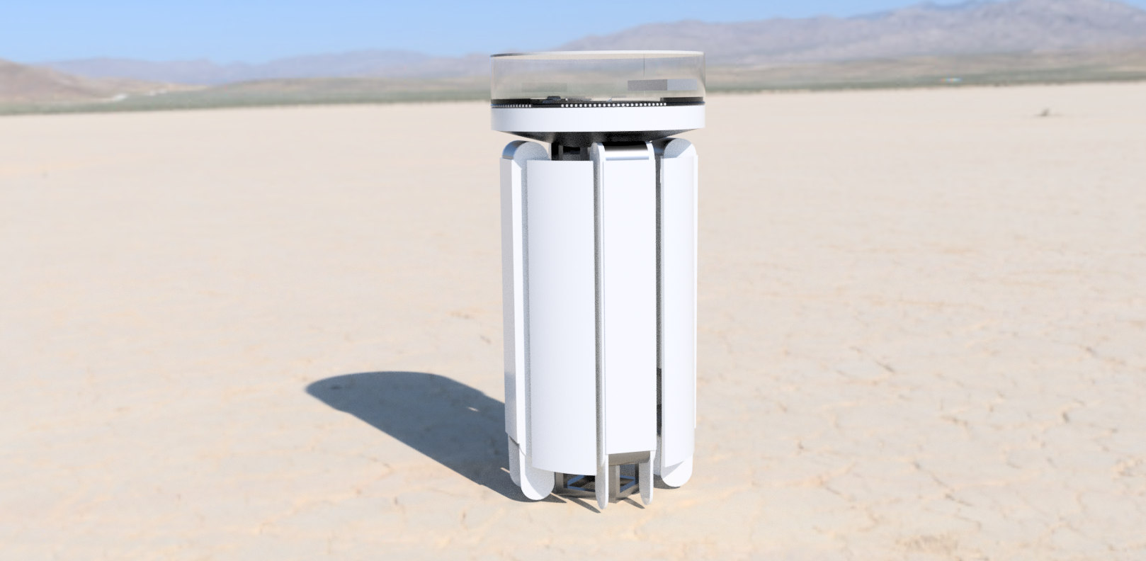
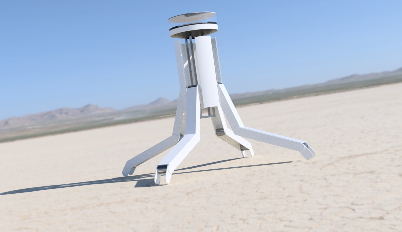
07/27/2018 at 01:00 • 0 commentsI watched a couple of Fusion 360 tutorials and had a go at modelling the legs. I had to use 360's joint functions correctly so I could adjust the leg positions for some concept renders. Here's a couple of renders to hopefully give a better idea of what I'm doing. Crude early concepts, with no wheels, arms or any details.
-
Collecting parts and building experience
07/22/2018 at 01:14 • 0 commentsSince my last post, I've firmed up my design (head-only render below) and assembled the new frame from 2020 aluminium profile. The new frame still has the hash design of the original to support the lazy-susan bearing but now has a narrow box frame below that will allow the legs to fold in around it and tuck under the head.Render of head CAD model. I've purchased the necessary polycarbonate for the protective camera shield and sensor mount, though I've not had chance to assemble it. I intend to use a Microsoft Kinect 2 depth camera (for point-cloud in ROS) and a stereoscopic camera for tele-presence operation, both mounted on the ring. I have the Kinect but I'm undecided on how to do the 3D imaging. To begin with, I'll be starting with a regular camera mounted on simple pitch-roll mechanism (yaw and active camera swapping taken care of by the ring). I have purchased a Logitech C920 for development purposes as it provides HD quality images with auto-focus and comes with stereo microphones (may help get started with remote sound location, though it'll probably be limited as the camera will be behind the polycarbonate shield).
Testing the RGB LEDs A water-resistant RGB LED strip (100 per meter) will provide short-range illumination for the cameras in addition to simple communication (of sorts) to anyone nearby. The LEDs will be recessed around the head, below the camera shield, above the sensor ring (the white strip in image above).
I printed the ring-gear segments in ABS and solvent welded them together with acetone. The ring was then screwed down through holes drilled in the lazy-susan bearing. A 3DP 8T pinion gear mounts to the gearhead motor to drive the 64T ring-gear. Yes, it hurts if you absentmindedly trap a finger in there.
Aluminium angle and 6mm polycarbonate (I used what I had handy) form the bridge which carries some electronics and a slip-ring. A small polycarbonate deck spans the width of the bridge above the slip-ring to keep an IMU (MPU6050) centered. The IMU will be used to keep the robot level and balanced. The electronics may be re-housed in waterproof enclosures if I ever get this thing mobile.
I had an IR photo-reflective sensor counting teeth and a magnet operating a reed switch to detect the home position but I was unhappy with the performance. The resolution of the 64-tooth ring-gear and sensing method wasn't giving the results I wanted so I swapped in a 600-tick rotary encoder on a second 8T pinion.
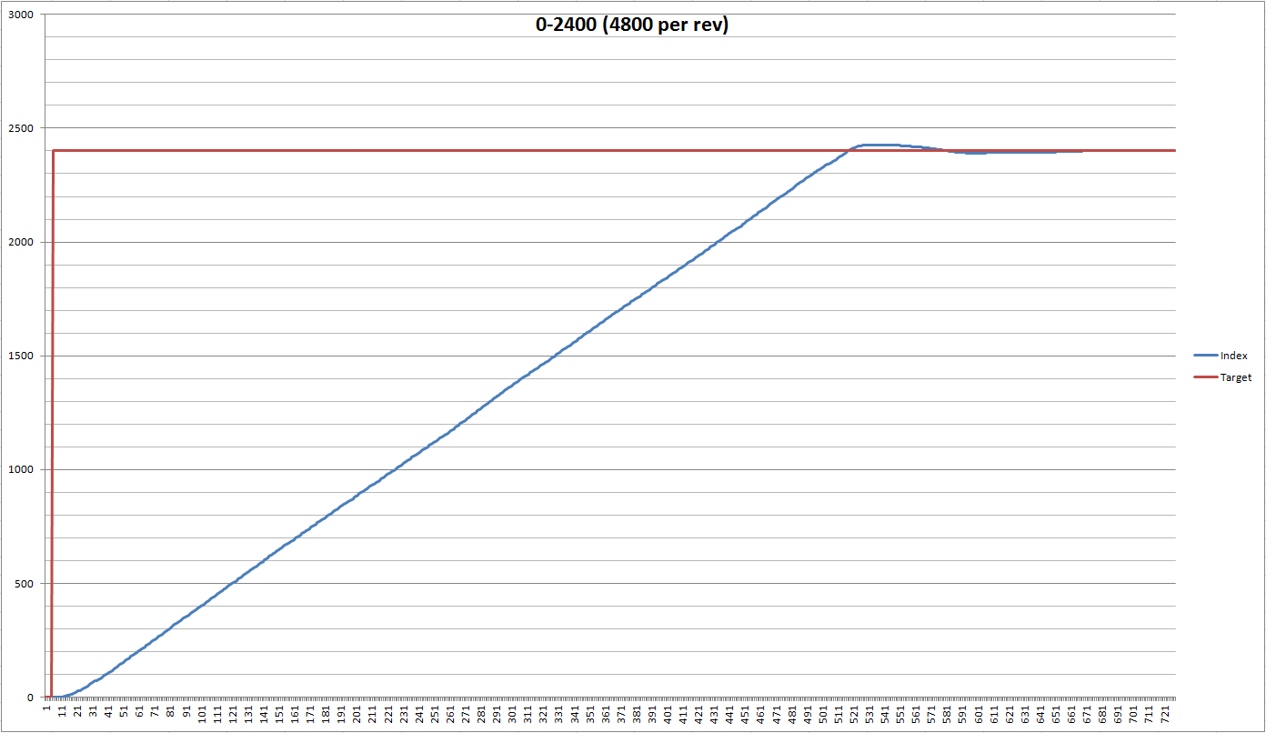
PID
My DIY PID position control code was then giving reasonable results but I knew it should be capable of better. I've long known the concept of PID control but there's nothing like getting your hands dirty to really drive it home. Below is one of the many plots I made when trying to tune the PID values.
My DIY PID code wasn't too bad for a first attempt. I'd type in a target position on a serial terminal and for most positions, most of the time, the head would turn reasonably enough, but still it could be better. Too much hunting that was hard to reduce without increasing the time to target.
The results I was seeing suggested my proportional calculations were suspect. I couldn't see how the relatively simple code wasn't functioning but I also admit I'm not an expert. Time to try known-good code so I swapped to the Arduino PID library and started the whole tuning thing again. You can spend the rest of your life tweaking PID values; constantly trying to get slightly better performance under slightly different conditions. I need to draw a line under this. Find values that are good enough and move on. However, before I can do that, I need to fix the CW/CCW behaviour that I broke in the PID swap.
Ultimately the target won't be set by a step-change entry on a serial terminal but by a more fluid parameter coming from the head-tracker or another algorithm and that's not helping with the PID tuning. I need a more analogue way of setting the target position. I considered a 360° pot or rotary encoder but that would mean more work in the wrong direction. I need IMU data here so I should use an IMU, but can't use the one mounted on the bridge, it needs to remote.
IMU & BT
I've just got done testing IMU data transmission via Bluetooth HC-05 modules. The IMU will be mounted on a lightweight helmet worn the operator to track head movements. The helmet provides convenient mounts for sensors, processors and battery.
Testing BT link. Next I need to format the data to make it easier to extract and feed in as the target position (0-360°). The X and Y values will control the pitch and roll of the camera mount, eventually.
Then...
Then I can fix the CW/CCW behaviour of the head and perform final tuning on the PID allowing me to make the head shield and mount the sensors. I'll probably have a stab at the legs then.
Droidbot 07 - Wheeled-Quadruped
An ambitious mobile robot for testing my skills and learning new ones.