AltMarcxs
-
The UV curing liquid
09/29/2014 at 03:59 • 0 comments![]()
Good news it's seems that the 445nm laser can also cure this, but using only 2x 385nm LED isn't enough, the 415nm laser is much faster, have to make a heat sink for the last.
Keep bottle upright.
-
Putting electronics together
09/29/2014 at 03:50 • 0 comments4 axis or compressor stepper driver mounted: see https://hackaday.io/project/1970/log/10123
Laser control unit mounted on the Y axis:
![]()
The main control unit been tested.
![]()
-
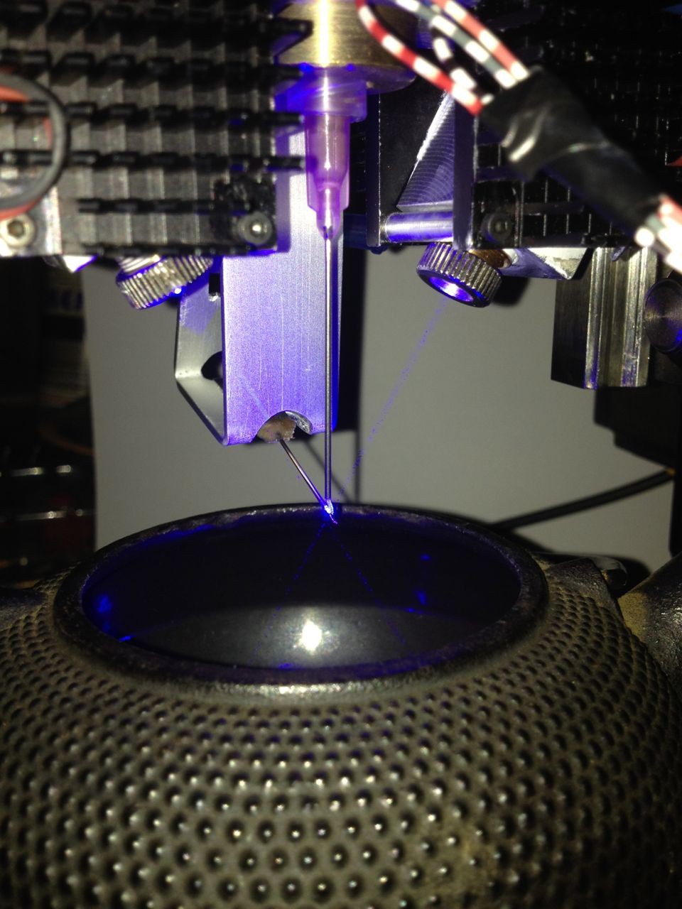
Pictures
08/20/2014 at 22:49 • 0 commentsBoth 3W Laser diode mounted
![]()
Laser on but picture with flash
![]()
-
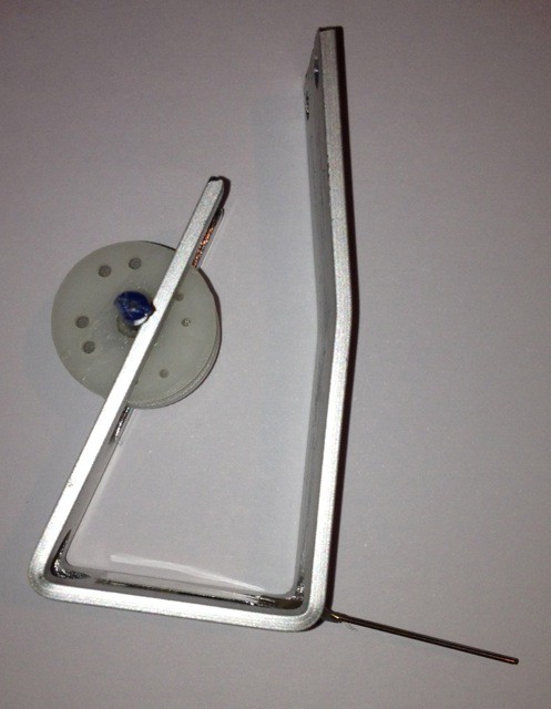
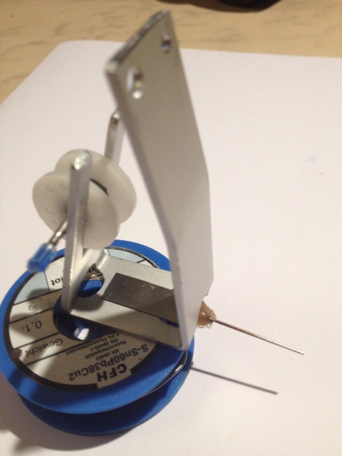
Wire feeder
08/20/2014 at 22:33 • 0 commentsSmall spool of Cu-wire (or other fibers) going through a needle.
This needle is just a bit lower than the dispensing needle, it keeps the wire on the PCB while Z goes to the solder position.
![]()
![]()
-
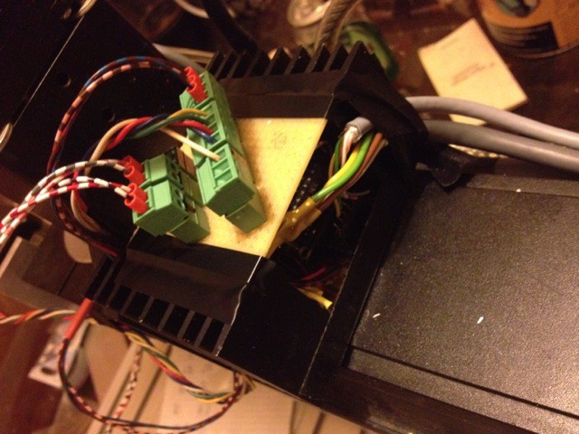
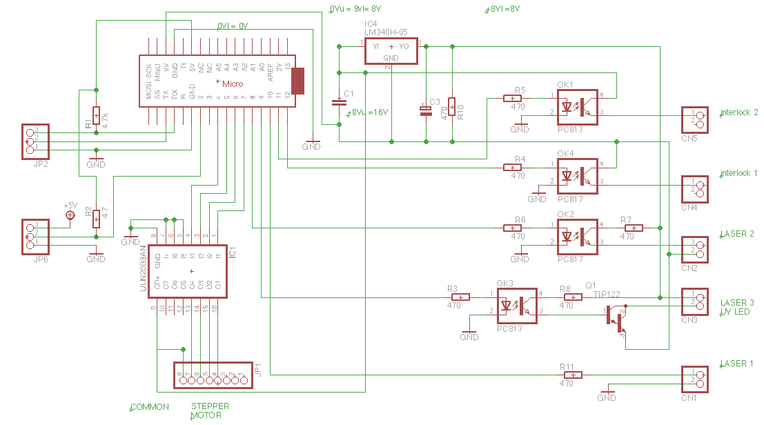
More electronics
08/20/2014 at 14:06 • 0 commentsThis board drives the laser drivers (Flexmod P3), the stepper motor which turn the assembly and additional 5V output used to switch on/off the UV laser mounted aside of the assembly ( will be used to expose PCB traces to UV ).
It's receiving it's data, the values of laser power and an angle value to move the stepper, from the coordinate board with the Teensy 3.1 on it.
It's also take care for E-Stop and Interlock.
It contains some opto isolator because each laser driver get it's own 8.5V (at 2.4A) but the stepper motor need more the 8.5V, bridging them and he get's 17V.
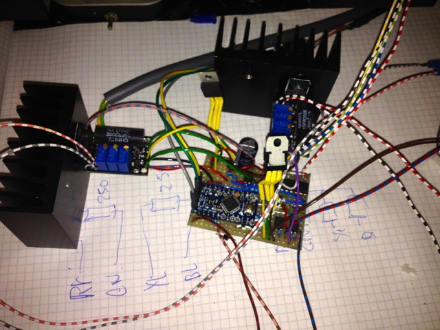
![]()
And it does work.
![]()
-
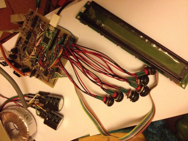
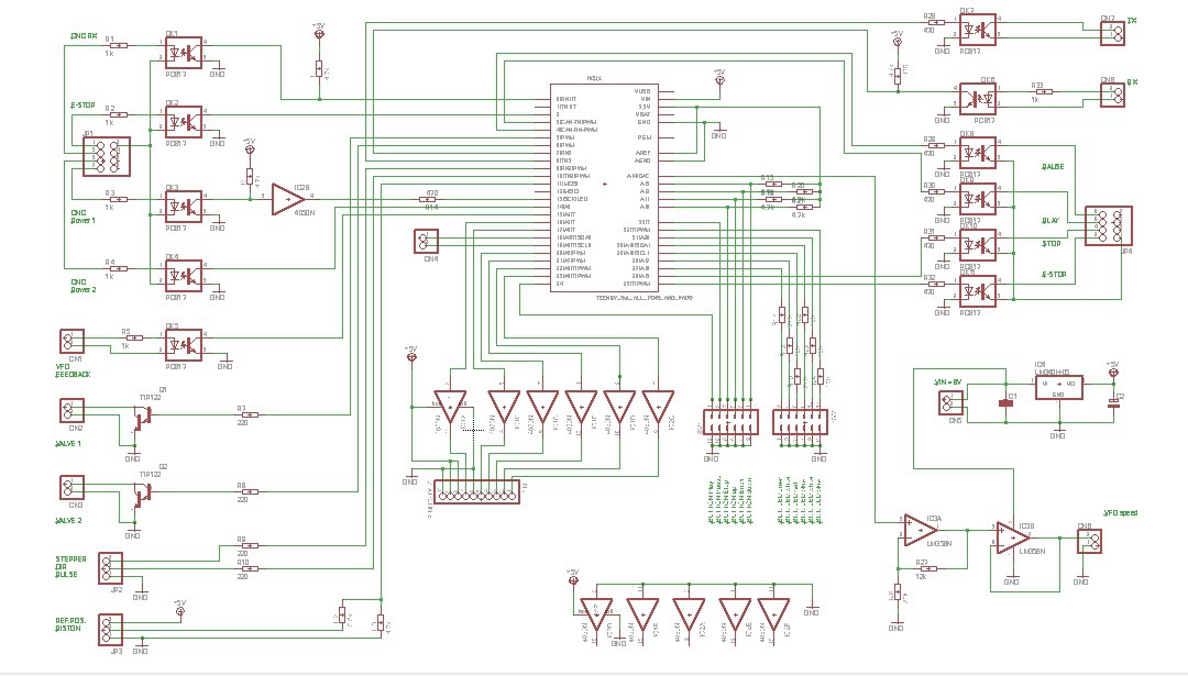
Update on Working on the electronics
08/05/2014 at 02:04 • 0 commentsHere the schematics of the Teensy controlled board, which receive via UART the coordinates and "Spindle Speeds" from the USB-CNC card, the VFD feedback, and 6 buttons with leds. STOP PAUSE PLAY are transmitted back to the USB-CNC card (also an E-STOP), then LEFT ENTER RIGHT will be used for navigating through menus and setups, displayed on the 2x40 char LCD.
Also 2 external valves are driven, a stepper driver ( the one for the compressor) also, a ref.position sensor for zeroing the stepper motor (again compressor).
And most important are the values send via UART to the Arduino mini-pro which sit on the machine with the laser driver and the ULN2003 for the other stepper motor (rotating the whole assembly).
![]() Update: Small modification in the schematics AND building it on perf. board.
Update: Small modification in the schematics AND building it on perf. board.![]() On this it misses the Teenys 3.1 for clarity ;-)
On this it misses the Teenys 3.1 for clarity ;-) -
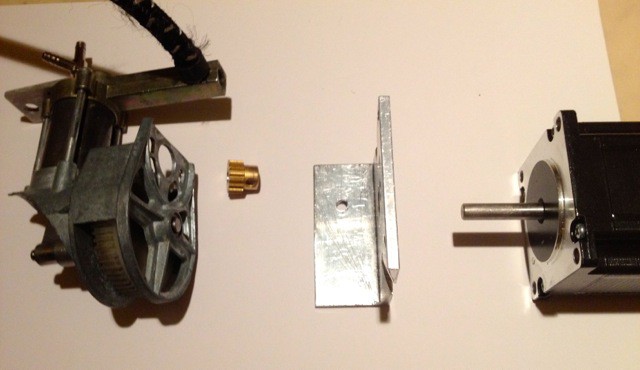
Compressor & Stepper Motor
07/30/2014 at 22:28 • 0 commentsMechanical parts: Scavenged compressor ( or buy a dirty cheap 12V car tyre compressor), a base plate, a pinion and a stepper motor.
![]()
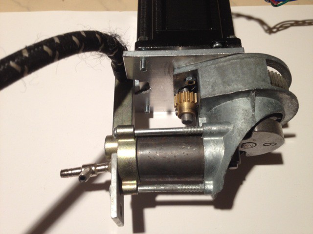
And assembled it does look like this:
![]()
-
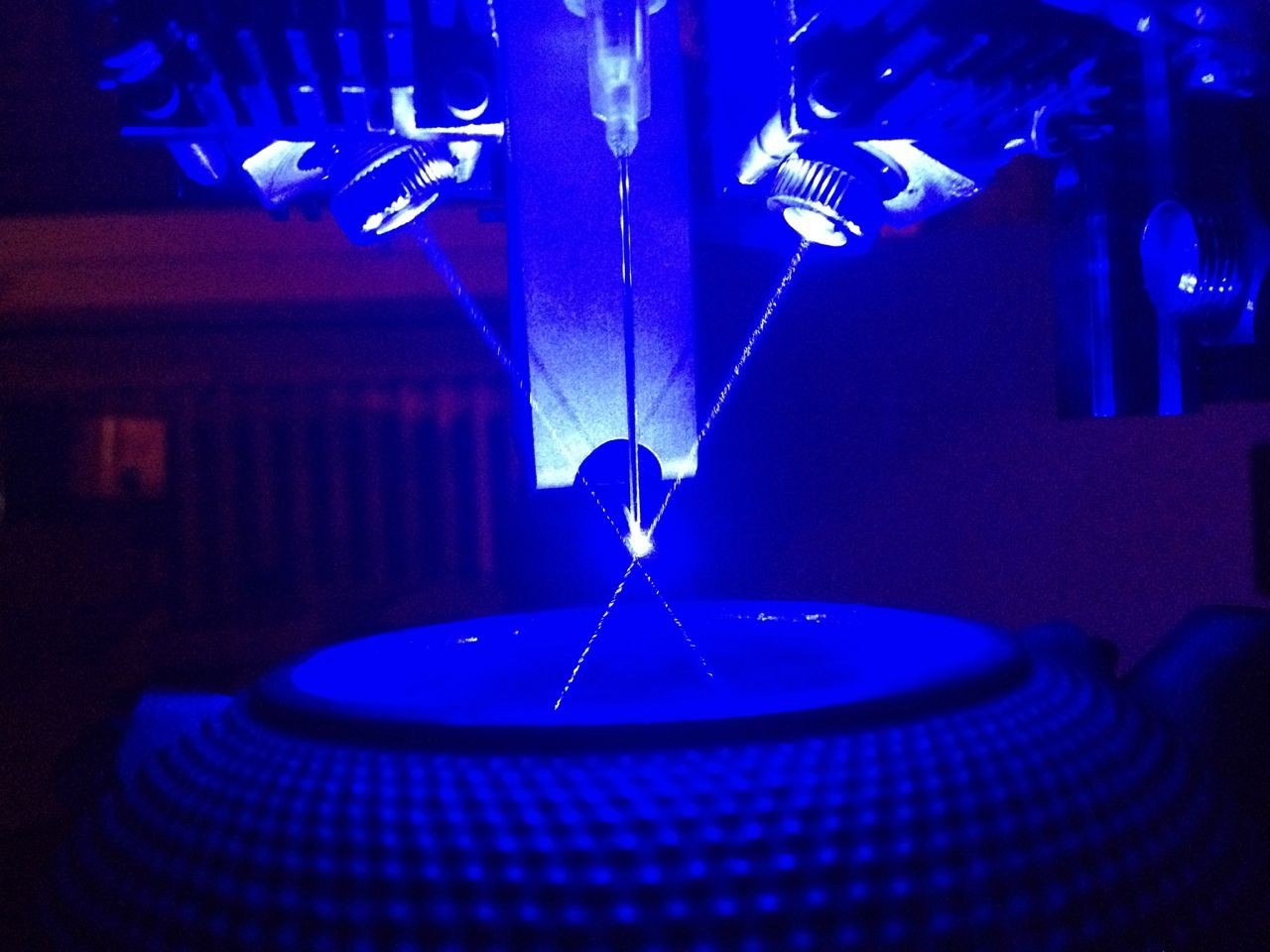
More pictures
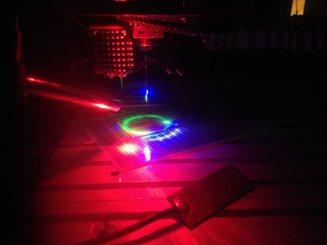
07/25/2014 at 16:40 • 0 commentsBlue, Green, Red Laser on
![]()
These are only for better view, blue and green crosses and red vertical (will be the UV-laser.
-
Got more stuff, received ordered electronic parts.
07/23/2014 at 23:27 • 0 comments10 Opto-coupler, ULN 2003, 2 rectifier, 2 heat-sinks, Transformer 50VA, cables and other stuff.
I have 2 driver boards for the laser diodes, they need a power supply, each laser diode run a max current of 2.4A at this rates the forward voltage get to 5.5V, the driver board need min. 1.5V more, = 7V. Transformer has 2x 7Vac rectified = 8.1V.
The transformer/rect./cap. stays in the CNC case, but the laser driver board have to be near the diode, that why I'm going to mount the heat-sink/driver behind the Z and atop of the Y axis. Will be great!
An LM 340 will produce the 5V for the Arduino and also provide Voltage for the UV Laser/LED which will be commutated with an TIP 127.
The ULN 2003 drives a small 5 wire nema 17 stepper used to rotate the whole assembly, it will get it's power from the bridged 8.1 +8.1 V supply.
I got to be careful with this setup, at least one of the laser driver board needs 2 opto-couplers for the PWM signal and on/off. The boards are nice you set the max. current for the diode at 100% PWM and at 0% you leave just enough current to keep the diode in a lasing state. (the diode will last longer)
The arduino will receive via uart, the calculated angle, the power of the lasers, and UV laser/Led on/off. Also it should receive/act to the emergency stop interlock.
CNC Add-on: Rot. Laser Soldering Paste applicator
Using a cheap tire compressor, driven by a stepper motor, to apply solder paste from a syringe and then soldering small wires to components.

 Update: Small modification in the schematics AND building it on perf. board.
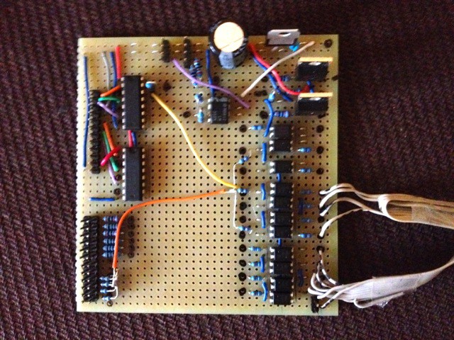 On this it misses the Teenys 3.1 for clarity ;-)