-
Rethinking Modes
01/09/2025 at 21:34 • 0 commentsThe way MINIBOT is currently setup isn't ideal. There are several modes I have it setup to operate in that are sort of clashing with each other.
Currently, the arduino pro mini that reads all the sensors and drives the bot has 3 modes:
- Manual: In this mode the bot will not drive on it's own, it waits for serial data from the ESP32. If data is received it checks for control commands for driving, etc.
- Autonomous: In this mode, the bot will drive around randomly. If it comes close to an obstruction, it will turn until it has a clear path in front and keep driving. After 30 turns it will go into sleep mode.
- Sleeping: The bot goes into deepsleep, wakes every 8 seconds checks for incoming serial data or activity from the motion sensor. If the motion sensor is triggered it goes back into Autonomous mode.
While the Arduino is doing the above, the ESP32 wakes from deepsleep every 5 min. upon waking it sends a command to arduino requesting sensor readings. If the battery voltage from that data is less than 3 volts, or it doesnt receive that data in a set amount of time, it goes back into deepsleep for another 5 min. The ESP32 at this point has 2 modes as well. It saves what mode it is in in the RTC memory so it can remember when it wakes up.
When first powered up, after doing battery check, it initially creates an AP. If no client connects to that AP in a set amount of time, it sets the flag to the second mode, then sleeps. If a client does connect. The bot can be controlled via a web browser, and video stream viewed.
The ESP second mode, upon waking, it asks for battery voltage, then it gets data back and if all is okay there, it connects to the secondary WiFi LAN i setup, takes a photo, and uploads it to the raspberry pi that is connected to that LAN via ethernet cable. I am successfully able to access all these photos from anywhere via tailscale.
After reading all this you may notice where there may be some issues here...
1st, if the Arduino is asleep when the ESP wakes up, it will time out waiting for serial data, just wasting battery.
2nd, the timing has to be just right after turning it on and connecting to AP to enter manual mode. Then once disconnecting, the bot has to be power cycled again to reenter manual mode.
3rd, I am not sure why, but after the bot goes into sleeping mode, it has been having issues after waking up. Or it doesnt want to wake up.
To solve these problems I need to rethink what is controlling what...
I think the best angle to go at this is remove the AP mode. I was going to do that anyway because I want to manually control the bot through the Pi via tailscale. Then I need to rethink how the bot is waking up. I think instead of the ESP32 sleeping for 5 min, having the arduino be the one to wake it will be a better idea. I will need to solder a control wire between the two devices to use as an interrupt on the ESP.
Now the question is how to switch between manual and autonomous mode?
my idea is to have the manual control page be hosted on the Pi. The bot will connect to this page when it wakes, and if a flag is set for manual control, it will start streaming video and accept commands. if that flag isnt set, it will do the photo upload, then go back to sleep like normal. This might sound kind of annoying, because to control the bot, I would access that page, check manual then have to wait until the Arduino wakes the esp. If I still have its sleep time at 5 minutes that would be the annoying part. The longer the wait, the longer battery life the bot will have.
So I definitively have some refactoring to do. This all involves writing code on the Arduino, the Esp32 and the Pi server. All this just in case I want to remotely control the bot...
I could make it a lot easier for myself, just hand control of the esp to arduino for taking and uploading photos and forget about the manual mode... but what's the fun in that lol?
This was a long ramble, but that's where I am at with MINIBOT. Have just been figuring it out as I go so that's why the WiFi connections and serial communication is so convoluted...
-
Control Minibot From Japan
01/03/2025 at 02:13 • 0 commentsI don't plan to go to Japan, but if I did, I'd still like to connect to MINIBOT with my phone and see what's going on under my couch.
I already use Tailscale, so I will install Tailscale on the raspberry pi in order to access it from anywhere. I set up a second wifi router with a different subnet than my main router. The pi is connected to internet through wifi, and to the second router by ethernet. Now I can have MINIBOT and whatever other wifi sensors I want to talk to the Pi able to do so but not take up traffic on main router or be exposed to the main LAN.
(WWW)---(home router) | wifi | <TailScale> [Raspberry Pi] | eth | (router2) / | \ / | \ wifi wifi wifi / | \ [minibot] | \ ( OO( )( ) [?] [?] -
Serial Communication
01/02/2025 at 10:51 • 0 commentsI wrote some code to send data between Arduino and esp32. For 2 reasons. Actually 3 and maybe more.
1st, I want the esp32 to know what the battery level is. I want it to sleep if the battery is low. I could have just added a voltage divider and wired it up to battery like the arduino, but it is deep in the mess of wires and has some hot glue holding it in place, didn't want to pull it and solder an analog wire on
2nd When the robot is being controlled manually, I'd like the sensors to be visible on the control webpage.
3rd, I may want to upload some or all of that data at some point.
Most of all of this is about timing, because if the ESP32 is asleep most the time, when it wakes up it sends a code over Serial to Arduino, and the arduino replies with the sensor readings, including the battery voltage.
I was having all sorts of issues debugging why it wasnt working properly. I did find some bugs and improve the serial code, but I was still having issues. Eventually I figured out the library I was using for the DHT11 sensor wasn't working properly. It would get stuck while trying to read the sensor. I just found a different library and it was working great after that.
The second issue is I want the arduino to sleep at times as well... what if the arduino is asleep when the esp32 wakes up and needs data?
I figured out I can wake the Arduino with the Serial RX pin. So when esp32 sends that control character, the device wakes up.
I am working on setting up a second wifi router I plan on having connected to a raspberry pi. the robot will use this wifi connection, and I am hoping I can tailscale into the pi and control the robot from anywhere in the world. We'll see...
![]()
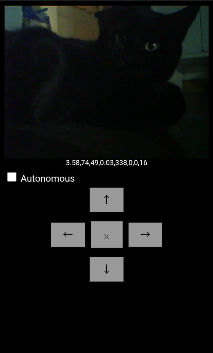
my cat still doesnt know what to think of the MINIBOT.
-
A Hat For MINIBOT
12/30/2024 at 22:27 • 0 commentsThere are a few modifications I will make on the bot today.
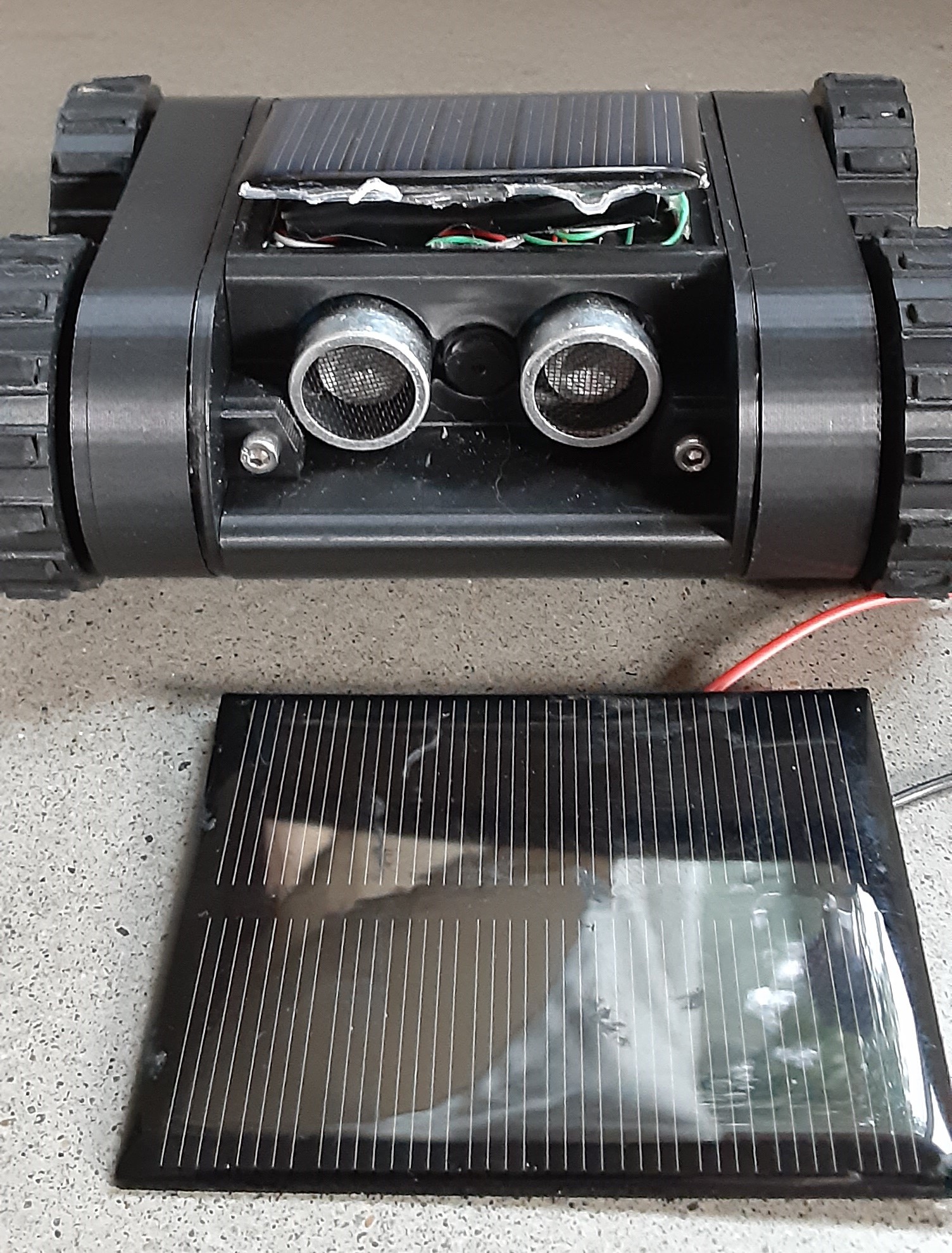
The first is the solar panel. Where it was mounted currently, the Arduino is just beneath it, as well as a mess of wires. I had to put hot glue down fast then put some pressure on the solar panel to get it to go into place. But after placing the bot under a very bright light the hot glue softened and the panel lifted up.
![]()
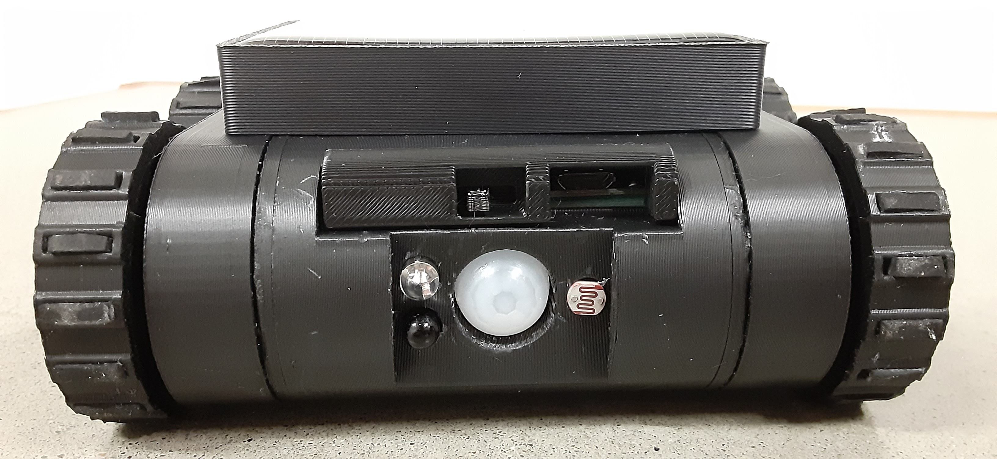
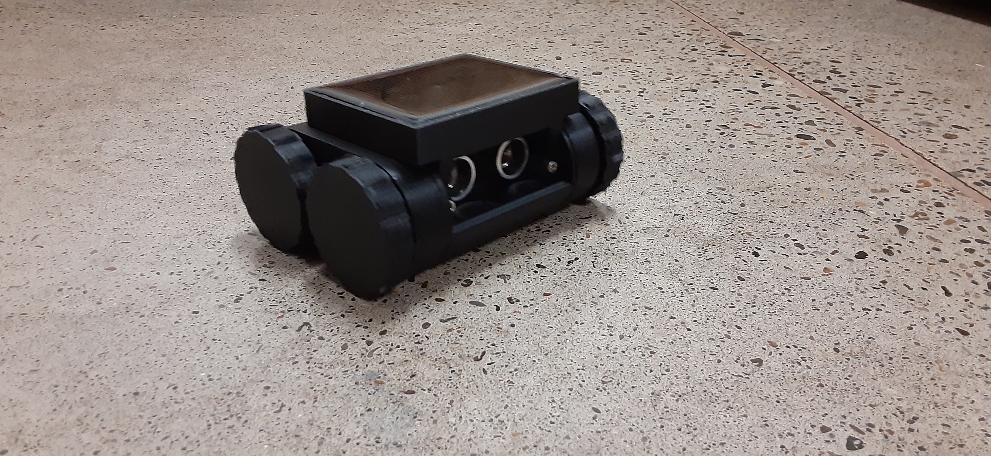
I am going to print a "hat" or bracket of some sort, that can be easily removed that a larger solar panel will fit into. This will also allow easy access to the Arduino as well as plenty of space for the wiring.
The only downside to doing this is it will remove the ability of the robot being able to drive if it gets flipped over. But so far that has not happened, so I am willing to sacrifice that feature. I still want it to be as low profile as possible for driving under shelves and furniture.
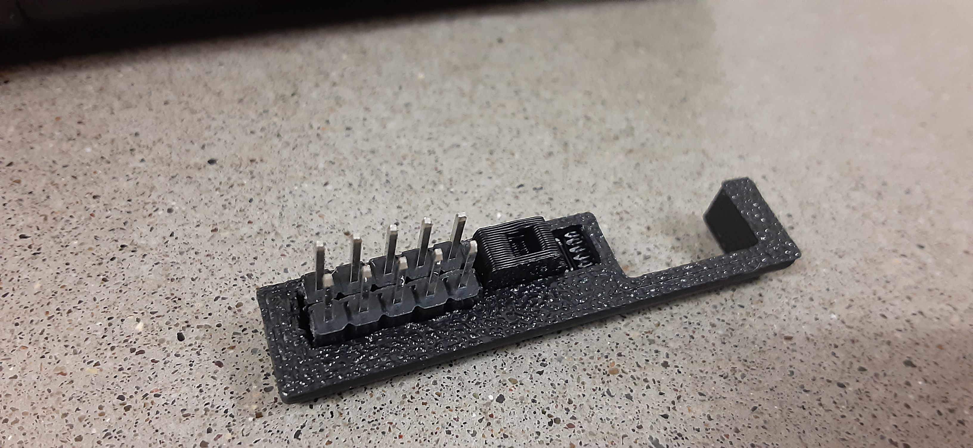
The second modification will be a small panel for the back ports and switch. As of now the switch is pretty recessed so it is hard to easily access. Also there is no internal connection for the Arduino and ESP32 Serial pins. This is done through the programming header. So The panel I will print that has a better switch on it will also have space for a male header that can be bridged to make those connections. This panel will be easy to unplug in order to program the robot.
The modifications are complete! I had to print the switch and port cover several times to get everything lined up. But now it's a bit easier to to turn it on and off, and the port cover has a header with the Tx - Rx pins from and to Arduino and ESP32 bridged, so no need to jump with wires.
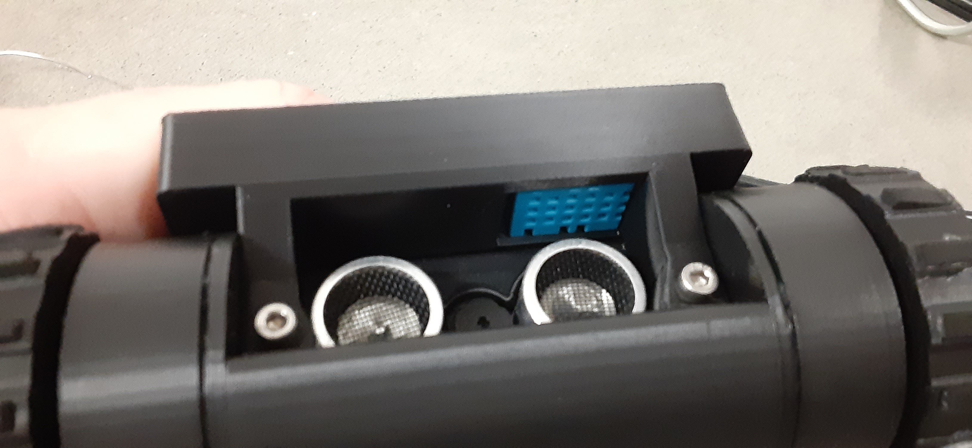
With all the extra room with the added Hat for the larger solar panel, I decided to install a DHT-11 Temperature and humidity sensor. These sensors are not super accurate, but I had a bag of them in my modules box so figured I would throw one in. There is enough room in there to add a piezo buzzer so the robot can make some noise too.
![]()
![]()
![]()
![]()
Now I just need to update the code to handle the DHT-11 Sensor, as well as modify a few bugs in the Serial transfer function that I am using to pass data from Arduino to ESP32.
 Gordon