Close
0%
0%

Single Digit Nixie Clock

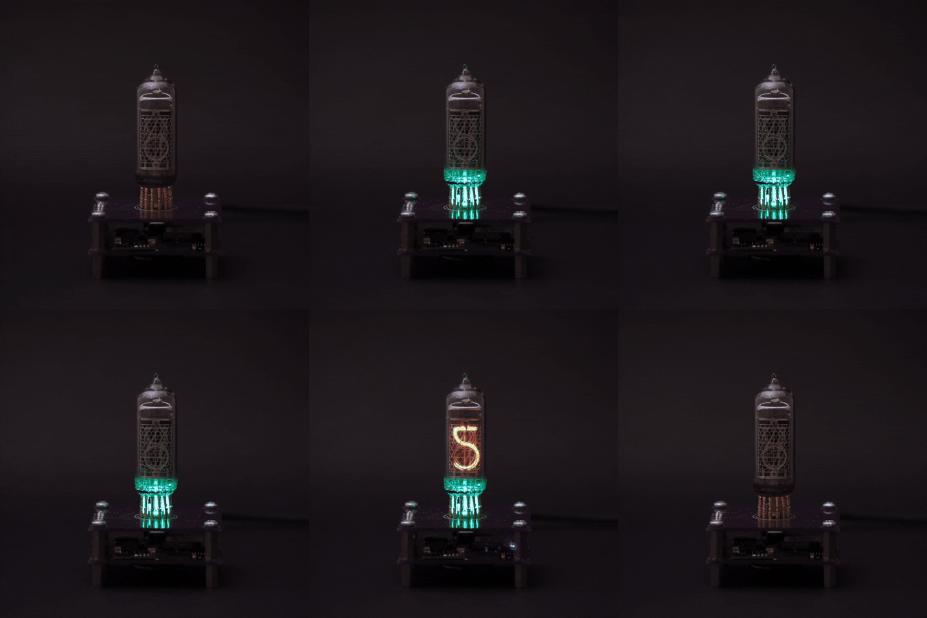
A small project combining ESP8266 with a vintage Soviet Nixie tube from the 70s to create an artistic clock

Similar projects worth following
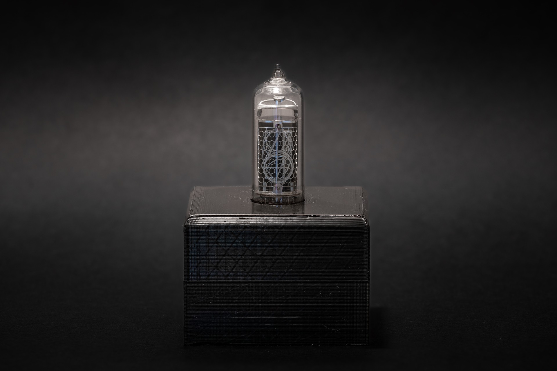
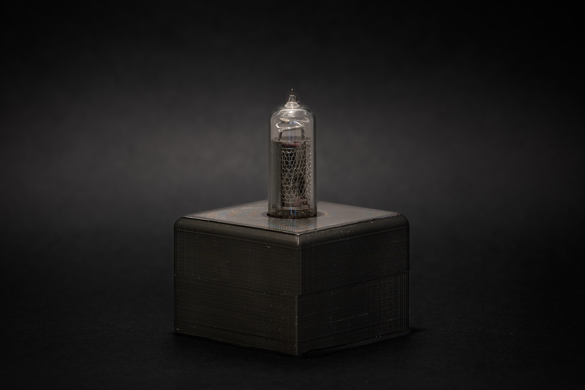
A small project combining ESP8266 with a vintage Soviet Nixie tube from the 70' to create an artistic clock.
Some of the key features:
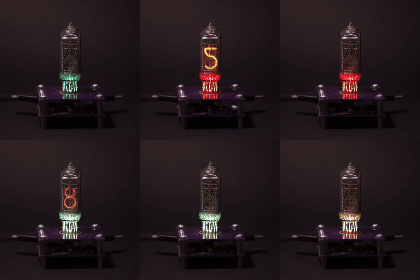
- Shows current time (hours and minutes) on a single nixie tube.
- Configurable RGB LED backlight lights up the nixie tube every second.
- USB powered.
- Hosts a web server for setup & configuration.
- Synchronises time with NTP server.

Schematic, PCB and firmware on GitHub: https://github.com/Deni90/singleDigitNixieClock

Introduction

I’ve always been fascinated by Nixie tubes. There is something special in them. Probably their shape, analog feel and the glowing numbers are making these tubes standing out from the new, more modern counterparts. Couple of years ago I bought a couple of IN-14 nixie tubes from AliExpress. To be more precise 3 of them. 

It was easy to decide what to use these tubes for: clock. Yes, yet another implementation of a Nixie clock. A bit boring, I know, I know… But, I wanted to implement my own version of it.

As you may know, at least 4 tubes are needed for a clock to show time in format like HH:MM. So, I had two options: order one more tube or come up with something different. Since nixie tubes are not on the cheap side I decided to use only one tube for a clock.

List of requirements

  • Power the clock from USB
  • Use Arduino IDE for development
  • Store time on a Real-Time-Clock
  • Interface the clock via Wireless
  • Reuse already bought components, such as ESP8266 and DS3231

Details

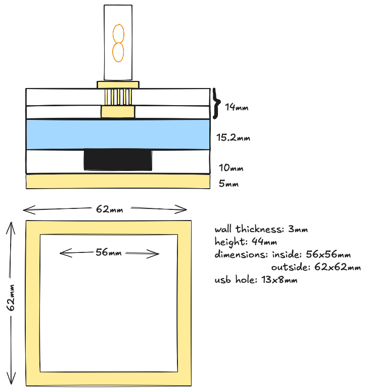
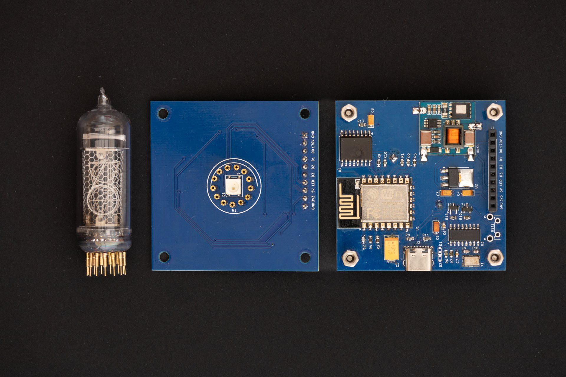
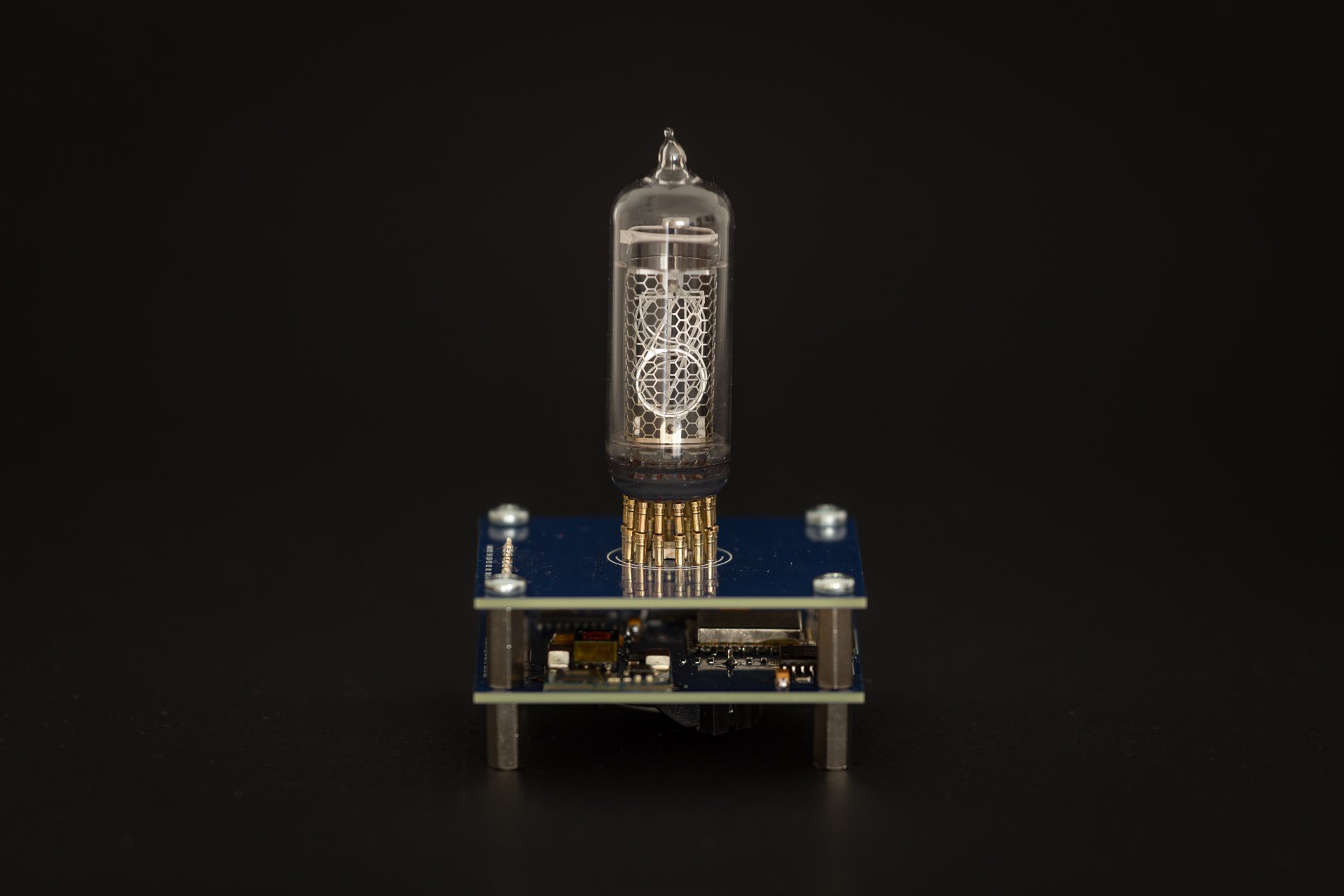
The end product is a stack of 2 PCBs where the bottom one is the control board containing the ESP with Nixie supply and the top one is the display board containing the RGB LED and the Nixie tube. 

Operating modes:

  • AP mode 
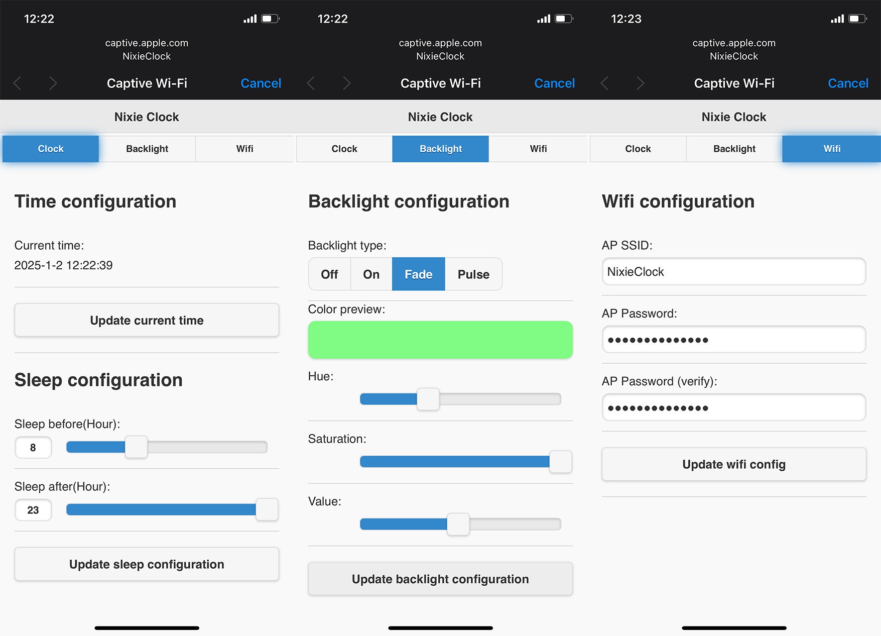
    • This mode is hosting a dedicated open wifi network called NixieClock. Its main purpose is to use it for first time setup to update wifi configuration. In addition, this mode will be activated when the clock is not able to connect to a configured network. Clock hosts a captive portal. A configuration page will be opened automatically upon connecting to `NixieClock` network.
  •  Client mode
    • In this mode the clock is connected to a configured wifi network. If there is internet access, the clock will synchronize its RTC with NTP server at startup and then every hour periodically.

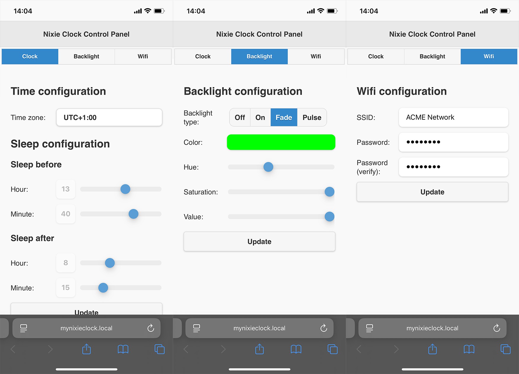
In both modes, the configuration page is easily reachable on the following URL: mynixieclock.local. There is no need to keep track of the IP address, the clock is hosting Multicast DNS (mDNS) server. mDNS is supported by Chrome and Safari browsers out of the box.

Short demo:

Note: The demo is without the Wifi tab.

Firmware

Firmware is written using Arduino IDE and PlatformIO

Project setup

  • Download PlatformIO IDE for VSCode
  • Install "Espressif 8266": PIO Home -> Platforms
  • Install dependencies defined in "platformio.ini": PIO Home -> Libraries

Model diagrams

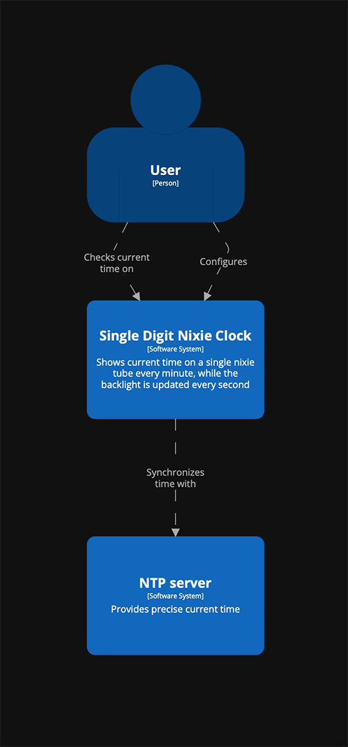
Context view diagram to present the general idea:
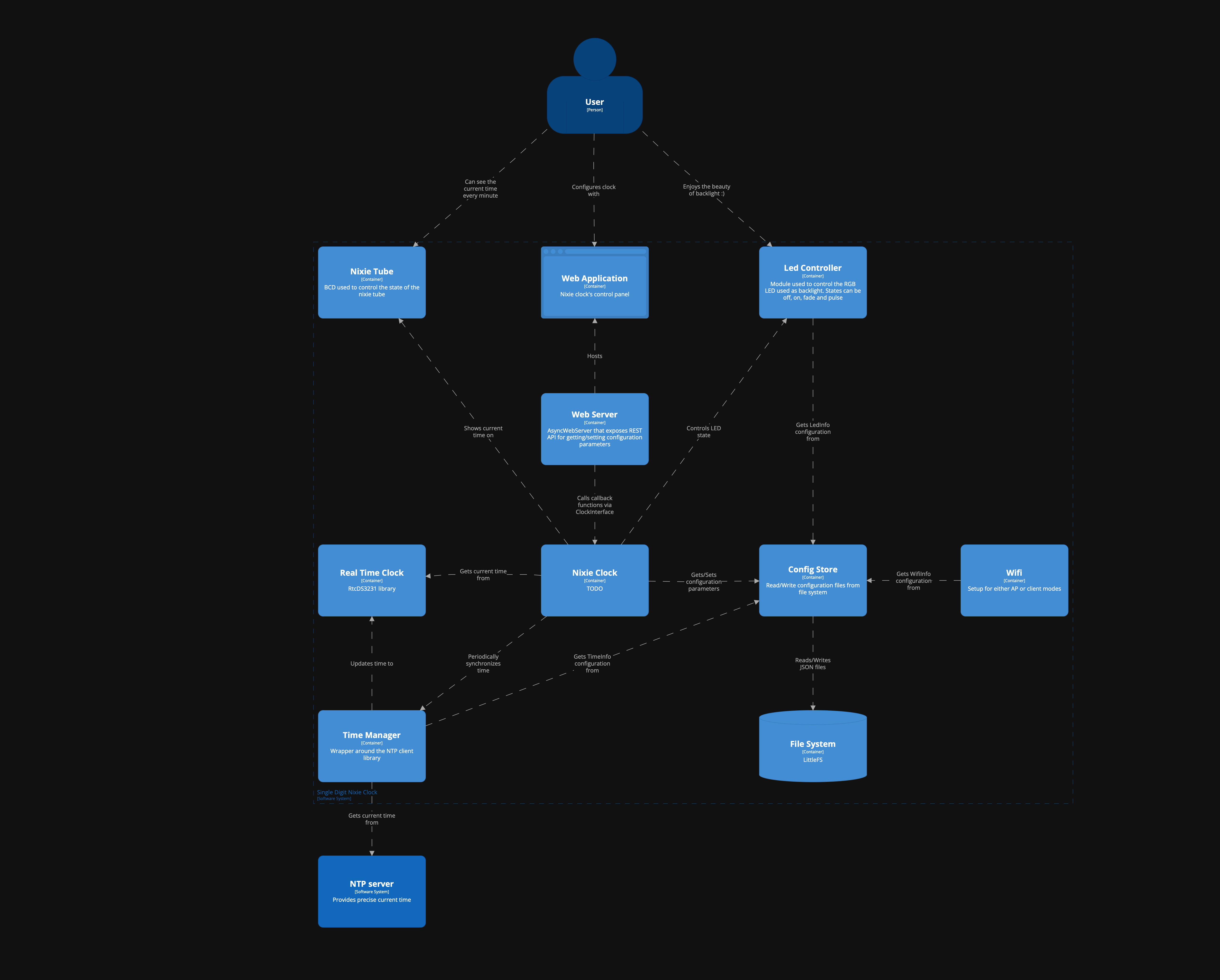
Software system view diagram that shows software components and their relationship:
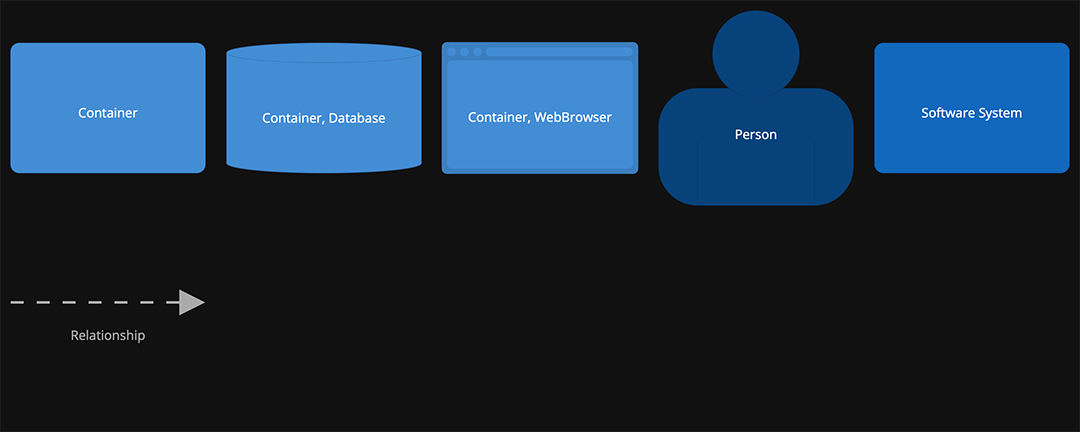
Legend:
REST API

End pointMethodBody (JSON) Description
/backlightGET{    
    “R”: <0-255>,
    “G”: <0-255>,
    “B”: <0-255>,
     “state”: <0-2>
}
Get color and state of
the backlight (RGB LED).
/backlightPOST{         
    “R”: <0-255>,
     “G”: <0-255>,
     “B”: <0-255>,
     “state”: <0-2>
Set color and state of
the backlight (RGB LED).
/clock/timePOST{
     “year”: <value>,
     “month”: <value>,
     “day”: <value>,
     “hour”: <value>,
     “minute”: <value>,
     “second”: <value>
}
Set current time.
/clock/sleep_infoGET{
     “sleep_before”: <value>,
     “sleep_after”: <value>
}
Get sleep mode configuration.
The time before and
after (in minutes)
the backlight will be turned off.
/clock/sleep_infoPOST{
      “sleep_before”: <0-23>,
      “sleep_after”: <0-23>
}
Set sleep mode configuration.
/wifiGET{     
    "hostname": "<HOSTNAME>",
   ...
Read more »

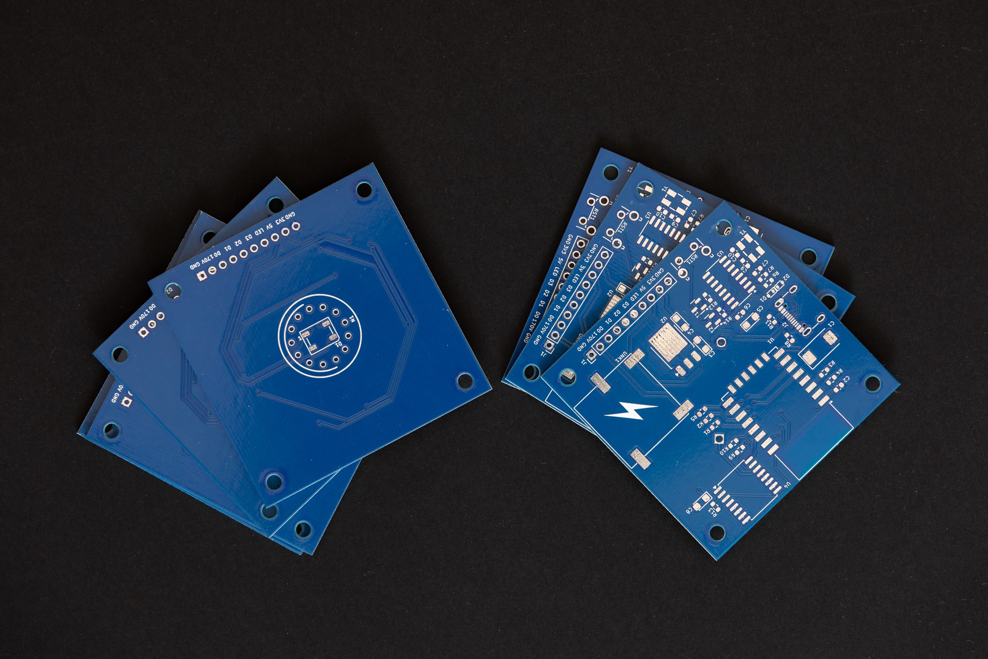
  • Hardware - new PCBs (thank you PCBWay)

    Daniel Knezevic01/31/2025 at 14:07 0 comments

    A huge thank you to PCBWay for sponsoring this run of PCBs!

    How does this story go?

    A representative from PCBWay contacted me because he was deeply impressed by my project and offered to sponsor a batch of PCBs to test out their services. 

    Firstly, I was surprised since no one ever showed interest in my personal projects. He was very kind to explain what they offer through the sponsorship and we made a deal.

    I have to be honest, I was a bit sceptical how this would go. It turned out they were very professional by sending the boards and paid all necessary costs including delivery. In addition to this, I have to praise simple and easy ordering through their website.

    Since I recently moved to KiCad, it was a perfect opportunity to try out the PCBWay Plug-in for KiCad. It provides a simple way to place an order in just a few clicks. There is no need to bother with exporting gerber files, everything is automated. You just need to update the PCB specification and fill in the shipping information on the webpage. That’s it.

    Another useful tool is PCBWay’s online gerber viewer, it is good for double checking all the exported files and to use images of PCBs in documentation.

    The entire journey from placing the order to receiving the package took less than a week. Incredible! PCBWay did a superb job, PCBs are amazing.

    Assembled PCBs:

    Stacked PCBs:

    Updates on Control board

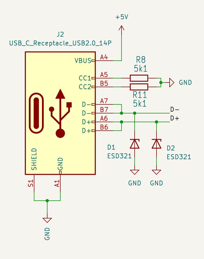
    Micro USB connector has been replaced with a type C connector. Nowadays, it is much easier to find type C cables at our desks because almost all devices switched to it. Despite it being harder to solder this connector without stencils, I found this change a logical step to keep up with current trends.

    Here is the updated part of the control board:

    Control board schematic is updated in the project's details.

    Lessons learned from this batch

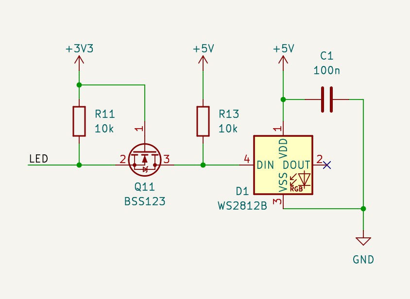
    Weird behaviour of the WS2812B RGB LED:

    I initially thought the problem was in micro USB connectors because the problem occurred with some cables. But, then I realised the problem might be in the fact that WS2812B is rated to 5V and the signal coming from ESP is 3V3. The LED worked on the breadboard while I was experimenting. I remember, I read somewhere that that’s fine… But, it isn’t. To fix this issue I’ve added a level shifter before the DIN pin of the RGB LED:

    Here is my botched PCB:

  • Hardware - Display board [v2]

    Daniel Knezevic01/20/2025 at 13:24 0 comments

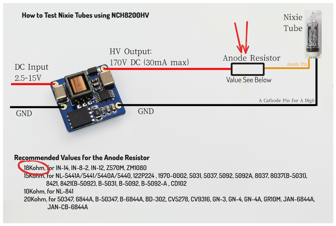
    Recently, I decided to move schematic & PCB designs from the good old, but sadly dead EaglePCB to KiCAD. I found this exercise good for learning how KiCAD works. While I was replacing components with ones from KiCAD I double checked data sheets and docs… Documentation for NCH8200HV has a wiring diagram describing how to connect a nixie tube to the 170V supply module. In the picture below there is an anode resistor that is used as a current limiter. I completely missed that. That’s the reason why the digits were too bright. The second thing I learned is to never overcurrent Nixie tubes.

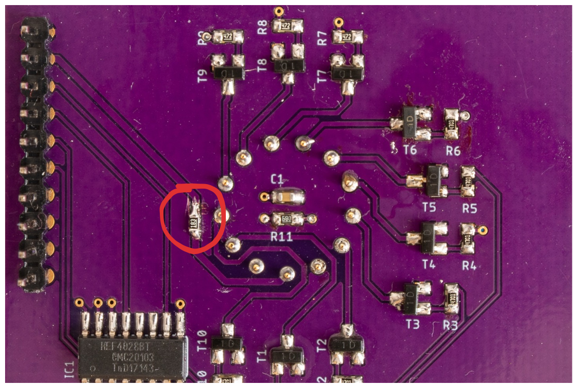
    To solve this issue, I cut the 170V trace on the display board and soldered an 18K resistor in series:

    Updated schematic is in the project's details.

    PCB

  • Web server

    Daniel Knezevic01/15/2025 at 16:31 0 comments

    Backend

    Backend is implemented using ESPAsyncWebServer.

    Frontend design

    Initially, the front end was implemented with jQuery mobile. Reason for choosing this framework was in its simplicity. It provides a simple way to create and control user interface components. One thing that always annoyed me was its low response time. It took too much time to load jQuery, jQueryMobile and theme resources. On top of this, this slow response time caused WDT resets.

    One more thing, I just realised that  jQuery mobile project is deprecated since October 7, 2021. Huh, when it comes to web related technologies, it looks like I'm living under a rock...

    To solve these issues, I opted to completely re implement the frontend using plain HTML, CSS and JavaScript. The end result looks almost the same as the previous design or even better. Responsiveness and stability increased significantly. The only drawback is now in maintenance and extension. It is required to implement everything manually.

    Size comparison

    jQueryMobile implementationCustom implementation
    Improvement
    404kB
    32kB1262,5%

    Performance comparison

    Average loading time of 10 tries:

    jQueryMobile implementationCustom implementationImprovement
    8695mS879mS988%

    Note: The jQueryMobile implementation caused restart of the ESP 3 times.

    Design comparison

    jQuery mobile design:

    Custom design:

  • Hardware - Display board [v1]

    Daniel Knezevic01/07/2025 at 10:58 0 comments

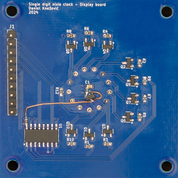
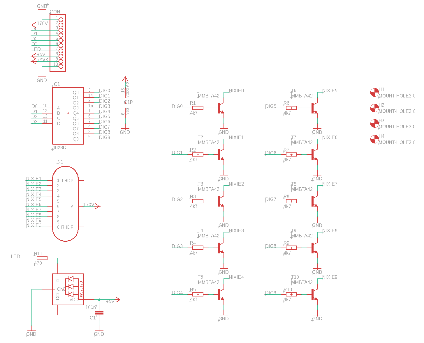
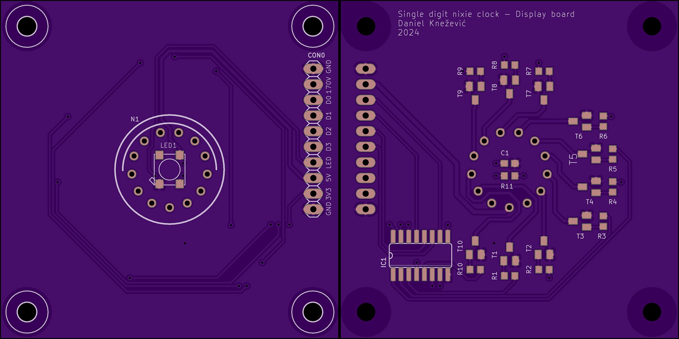
    Display board uses a CD4028 BCD-to-decimal decoder. Its purpose is to reduce the number of required GPIO pins from 10 to just 4 for showing digits from 0 to 9. Compared to dedicated BCD to decimal decoder nixie drivers (like K511ID1),  the CD4028 is a widely spread component and it is available in SMD package. Since CD4028 has a voltage range from 3.0V to 15V it is not compatible with nixie tube’s operating voltage of 170V out of the box. This problem is solved with MMBTA42, a high voltage transistor, rated to more than 200V.

    The rest of the display board consists of a WS2812B RGB LED and a pin header used to connect with the control board.

    Schematic

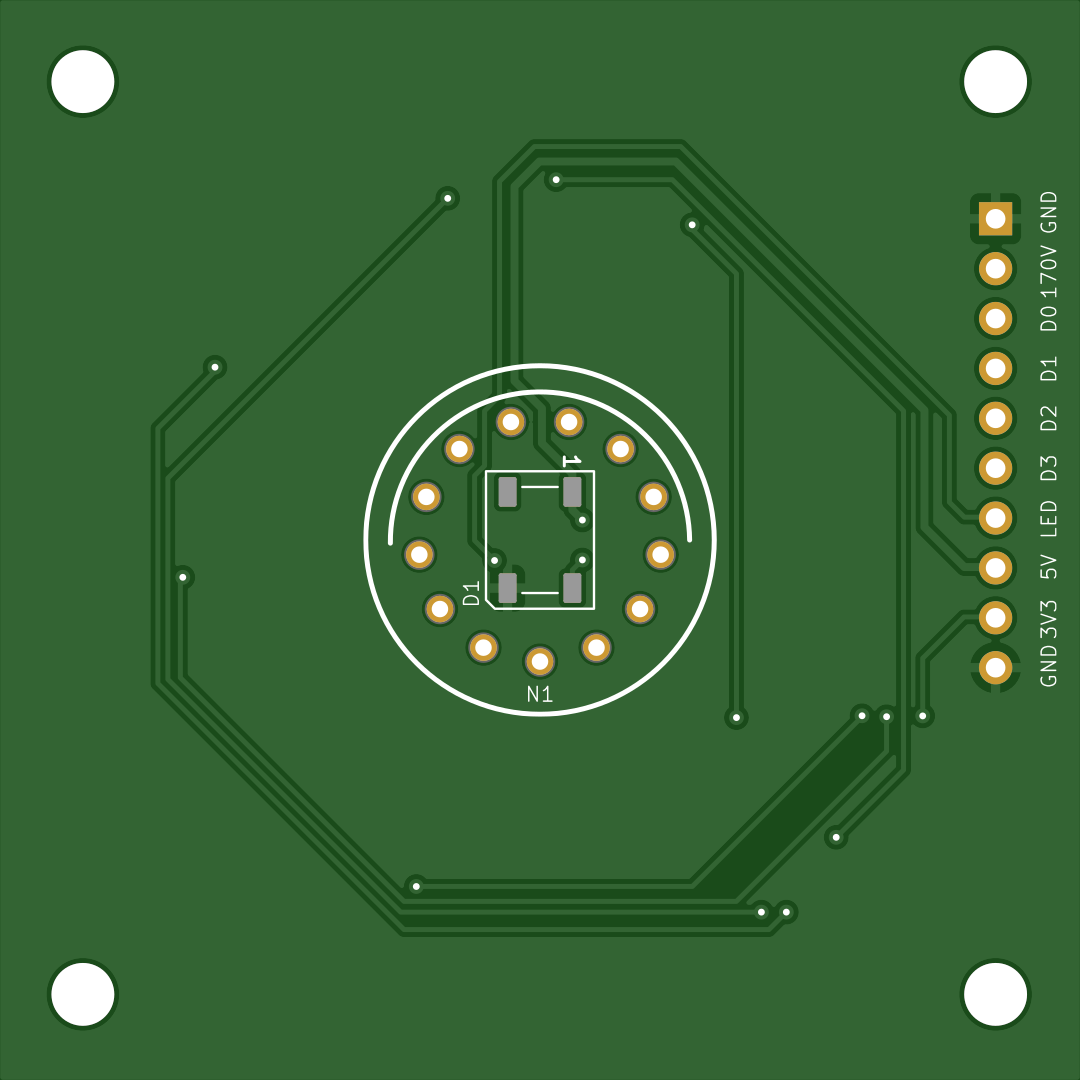
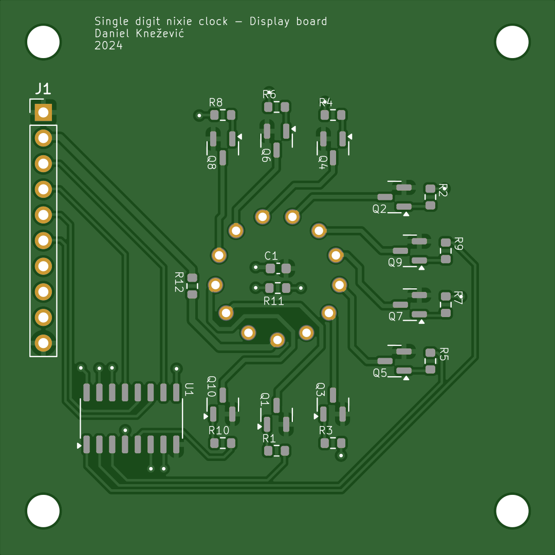
    PCB

  • Hardware - Control board [v1]

    Daniel Knezevic01/03/2025 at 15:57 0 comments

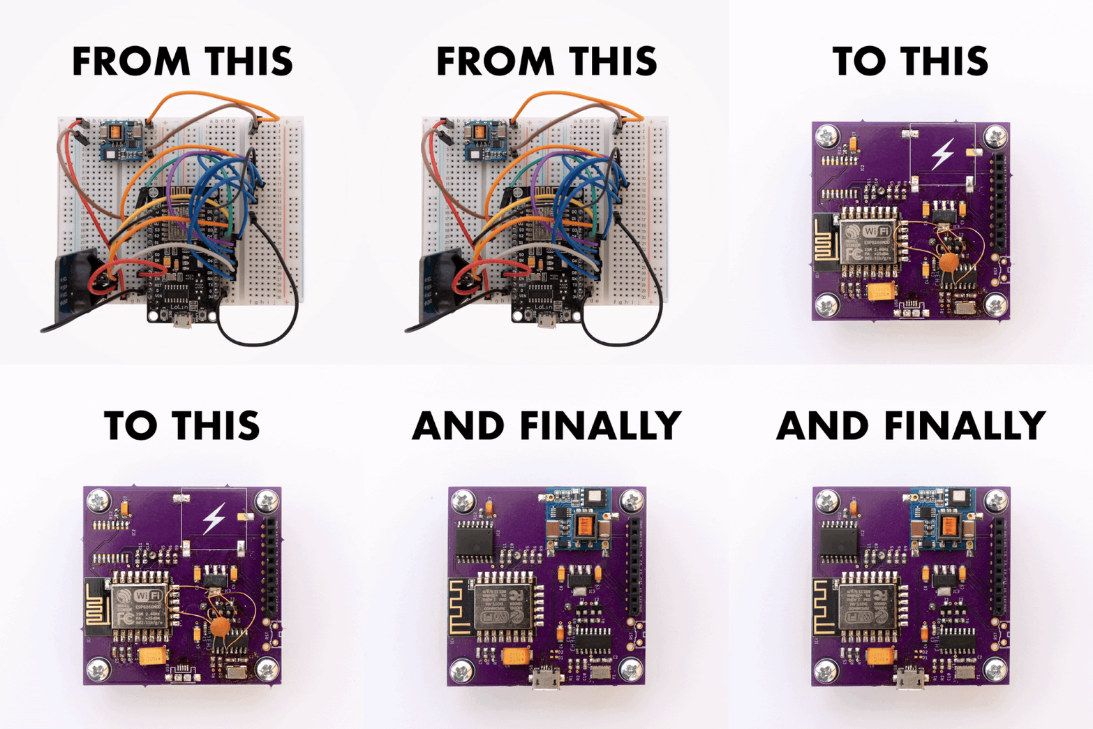
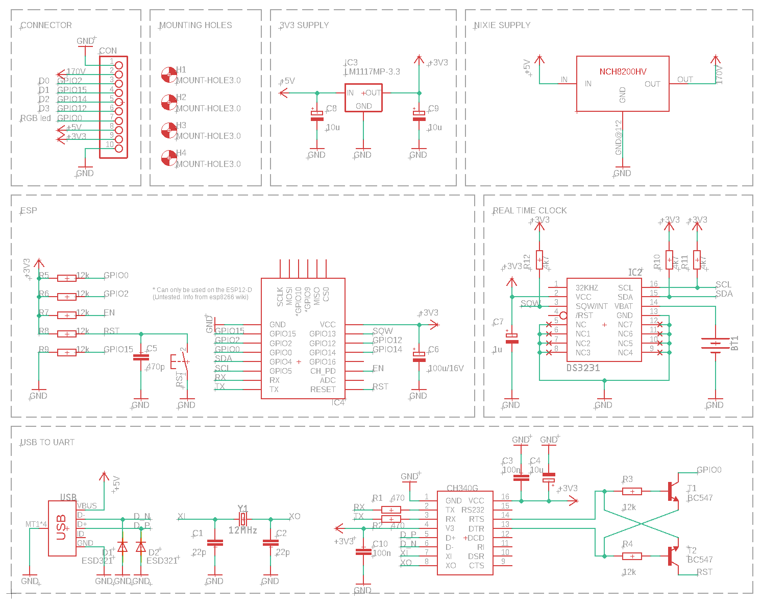
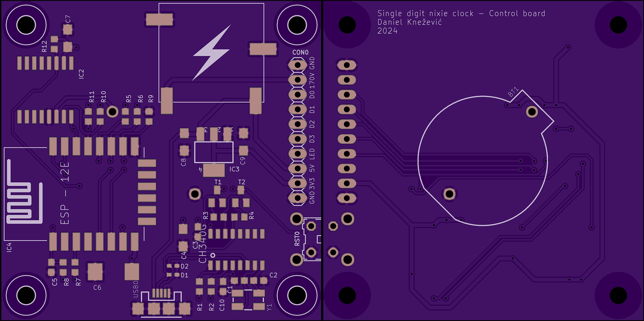
    For proof of concept NodeMCU was connected with a DS3231 RTC module on a breadboard. This was enough to start working the firmware. Later, a PCB was created. The PCB is basically a re-packaged NodeMCU design connected with DS3231 and NCH8200HV high voltage boost module board.

    Schematic

    PCB

View all 5 project logs

Enjoy this project?

Share

Discussions

Ken Yap wrote 01/18/2025 at 22:33 point

Ah yes, the teltale upside down 2 for the 5 in some Soviet tubes. Fun project.

  Are you sure? yes | no

Similar Projects

Does this project spark your interest?

Become a member to follow this project and never miss any updates