-
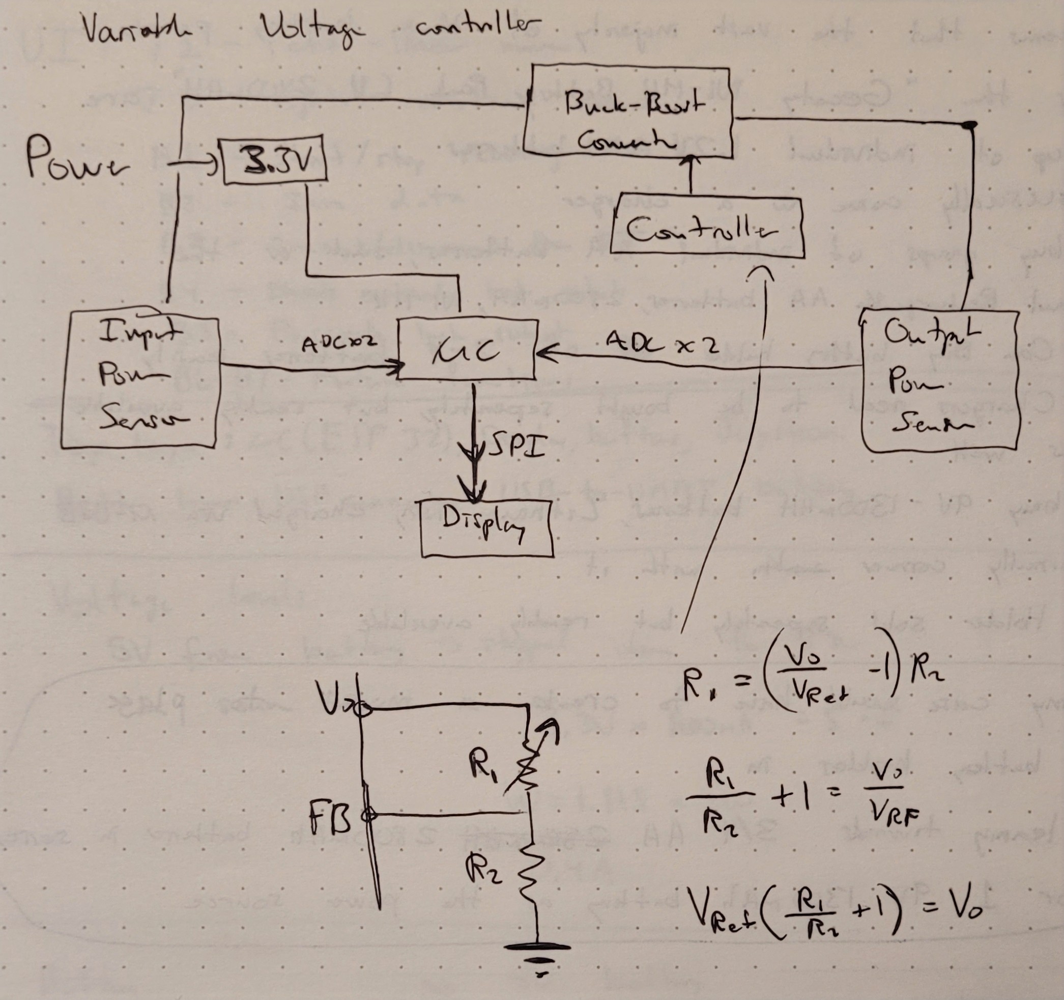
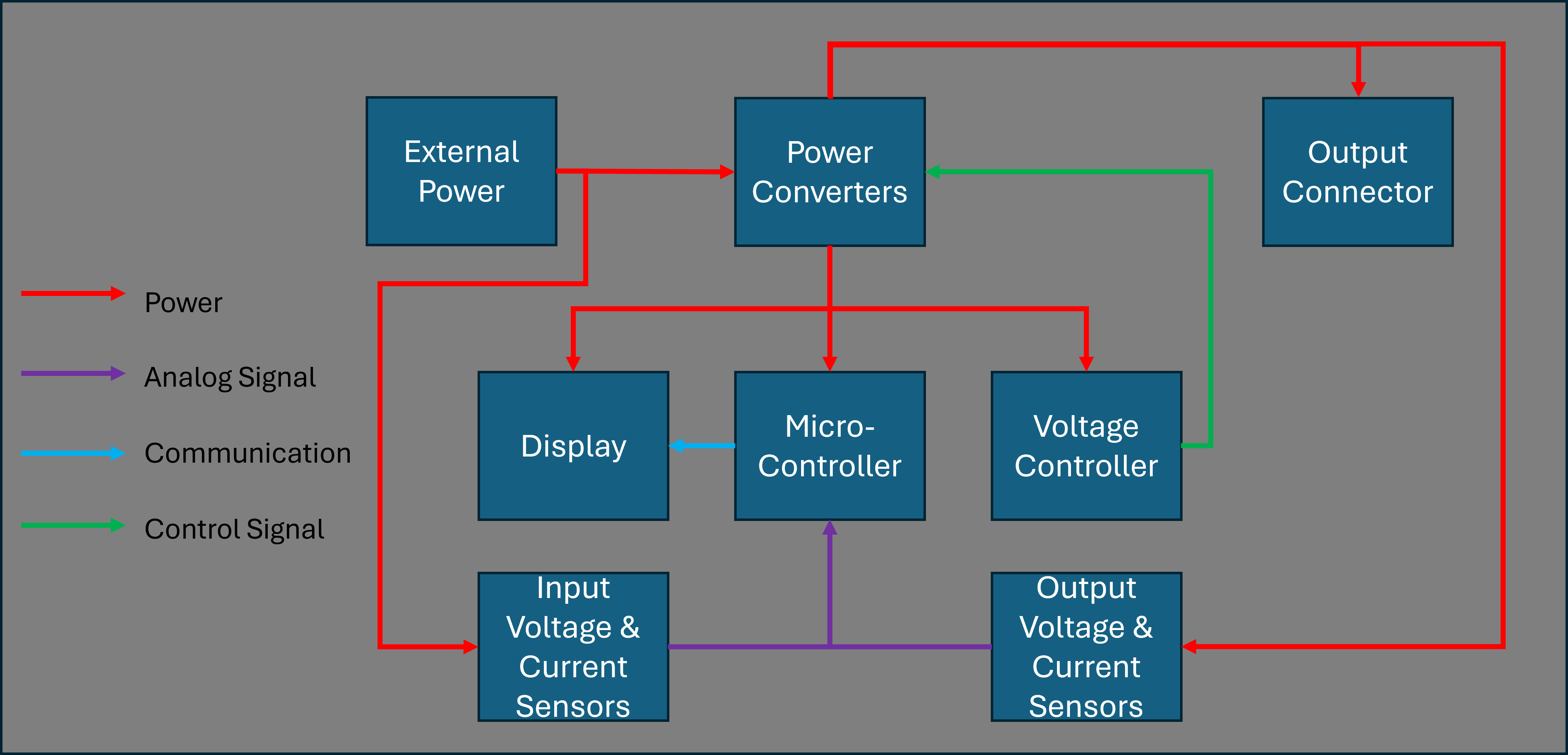
"Final" Block Diagram and Voltage Control Circuit
3 days ago • 0 comments![]()
- There will be no connection between the voltage controller and the microcontroller
- The potentiometer will be placed in R1
![]()
-
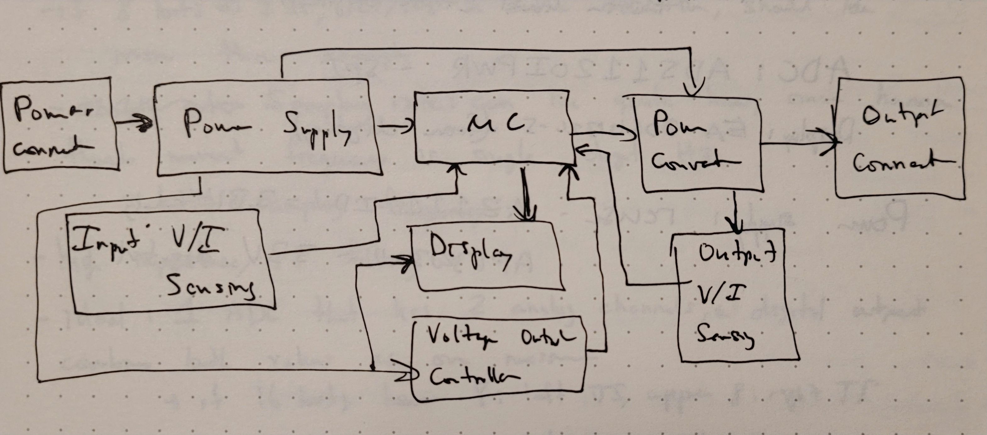
Initial System Block Diagram and Lower Level Requirements
3 days ago • 0 comments![]()
- Power Supply:
- 3.3V power for the microcontroller, display and output voltage controller
- Vi = 5 : 30V
- Will power the 3.3V regulator
- Sensed by input voltage and current sensor
- Powers output power converter
- Microcontroller:
- Low amount of processing, low clock speed required, 8MHz, maybe even 4MHz
- Has ADC pins (accuracy not a huge issue here)
- Need 5 (Vi, Ii, Vo, Io) + voltage output controller
- Peripherals: want SPI to communicate with the display
- Display:
- Show 4 rows of text at least
- Vi, Vo, Io and Ii for efficiency
- Possesses an SPI interface
- Output Voltage Controller:
- Outputs 0V to 40V DC
- Use a switching regulator for efficiency
- Adjustable
- Voltage Sensing:
- Vi and maybe Vo will be higher than 3.3V
- Will need to attenuate the value, will use a voltage divider and a voltage buffer
- Current Sensing:
- Will use "in-line" resistor and an amplifier
- Will use "high-side" sensing
- Resistive Current Sensing: Low-Side vs. High-Side Sensing - Technical Articles
- Power Supply:
-
Ideation
3 days ago • 0 comments- Voltage Controller:
- Variable voltage controller, connects to external power supply, can control the voltage outputted by the device, and monitor the current and voltage
- Refine Requirements:
- Should have voltage step-down and step-up capabilities
- Buck-Boost converter
- Can connect to multiple power sources (benchtop power supply, jack)
- Screen that displays:
- Input voltage
- Output voltage
- Input Current
- Output Current
- Efficiency
- etc.
- A knob to control the output voltage
- Should have voltage step-down and step-up capabilities
- Power:
- Can output up to 40V
- Can receive up to 30V
- Sensing:
- Input Current
- Output Current
- Input Voltage
- Output Voltage
- User Interface:
- Knob - potentiometer to change output voltage
- Display - to show electrical information
- Voltage Controller:
Variable Voltage Controller
Desktop device that outputs a variable voltage whose value is controlled by the user.
 Ghani Lawal

