Close
0%
0%

CM5 Cybergear and Dynamixel Controller

IMU and Raspberry Pi Compute module 5 controller for Xiaomi CyberGear BLDC motors

Public Chat
Similar projects worth following
I have been using Eagle for many years now, but after Autodesk announced that they would kill off the stand-alone application, I suspect that the pricing structure will also change dramatically. Being forced to purchase the full version of Fusion 360 to be able to make boards with more that two layers and be able to use multiple schematic sheets etc is a no-go for me.

Therefore, I decided to bite the bullet and convert to KiCad. I have to say that I am rather impressed. KiCad now seems more mature than Eagle and also easier to use in many respects.

I needed a new project for this "self learning" excercise. Since I already have sourced several CM5 modules with wifi, A CM 5 devkit and also have a few Xiaomi Cybergear BLCD motors lying around, I thought that a high level controller would be a nice project to get me started learning KiCad

The CyberGears are 24V BLDC motors with CAN interface (I believe that they can tolerate up to 30V).

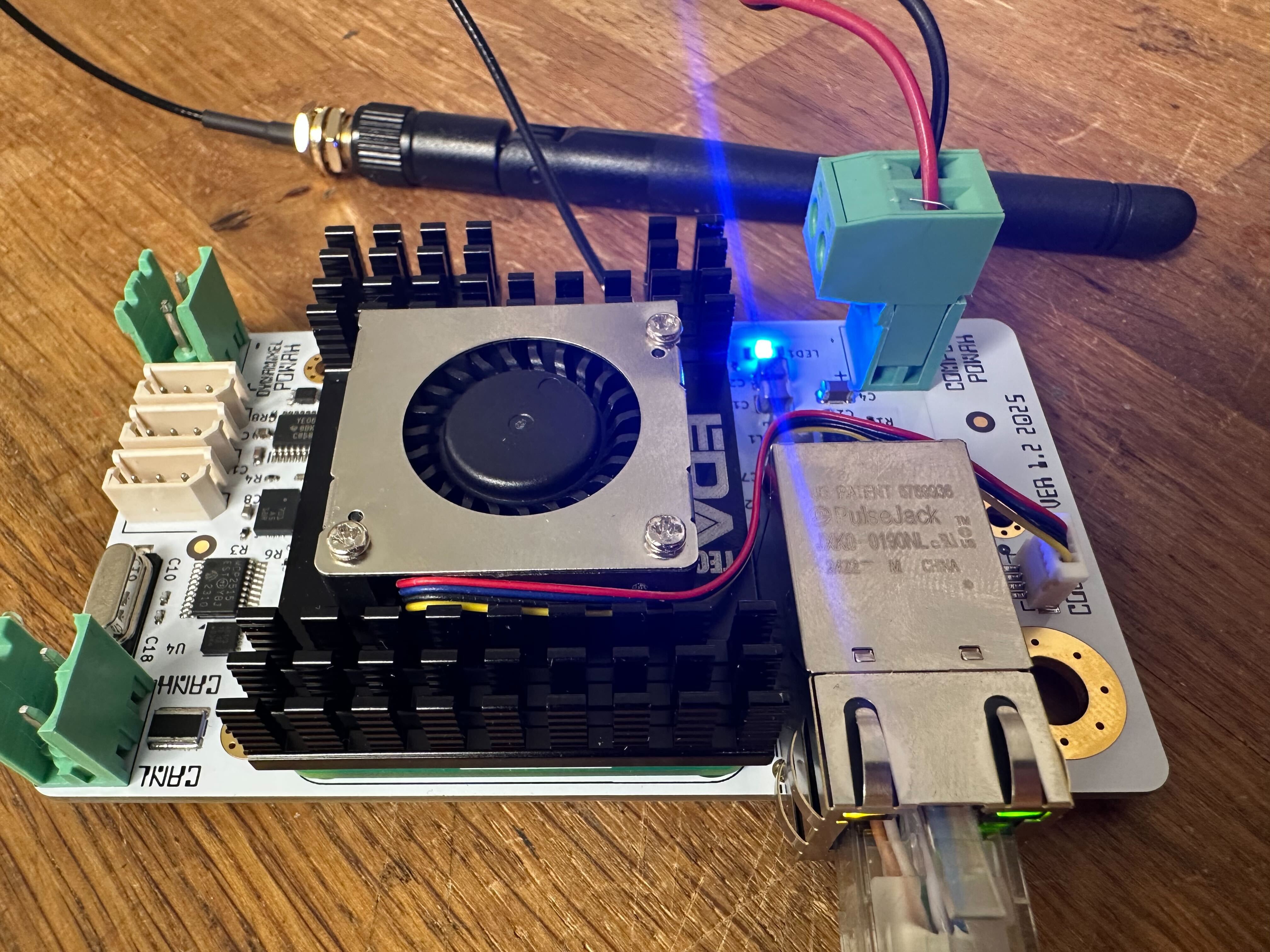
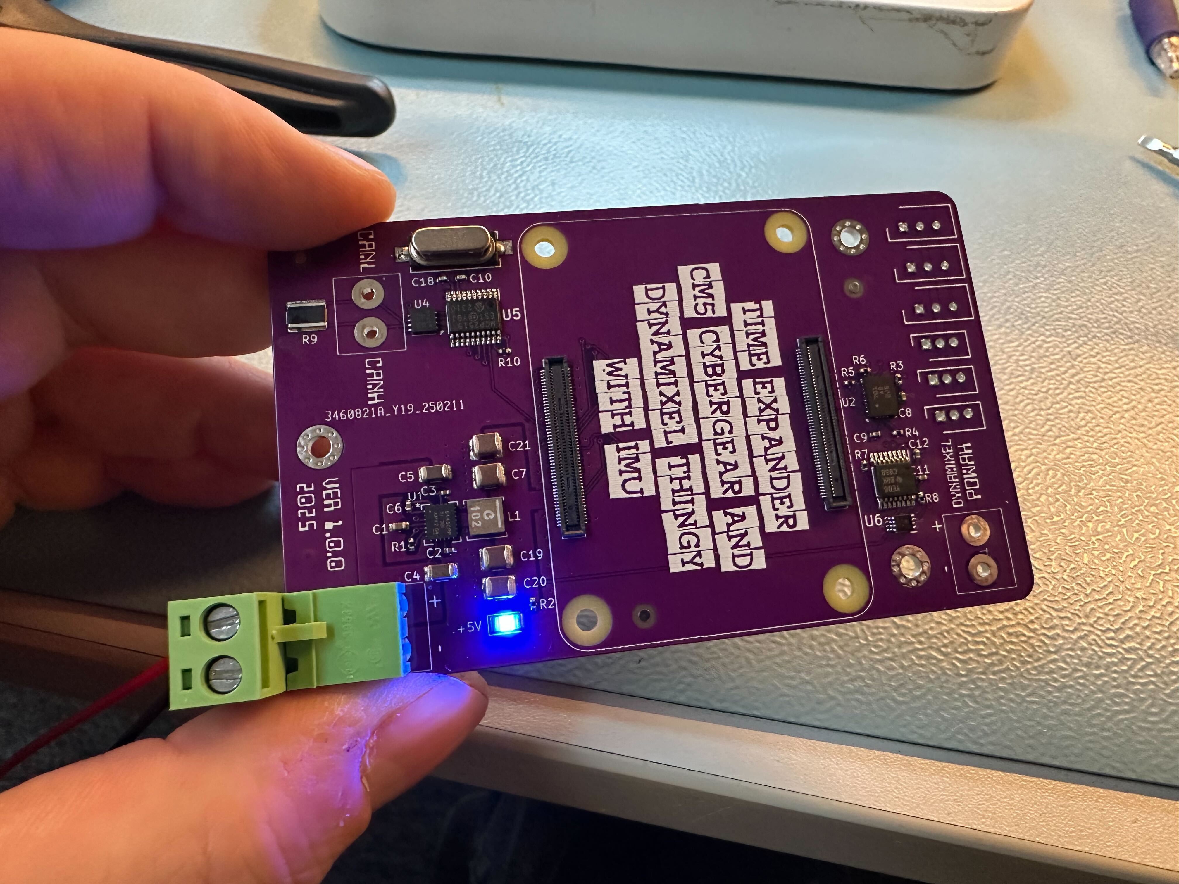
Ignoring passive components, the BoM currently consist of:

* Raspberry Pi Compute Module 5
* LM64460 Buck converter (max 36V input / 5V 6A output)
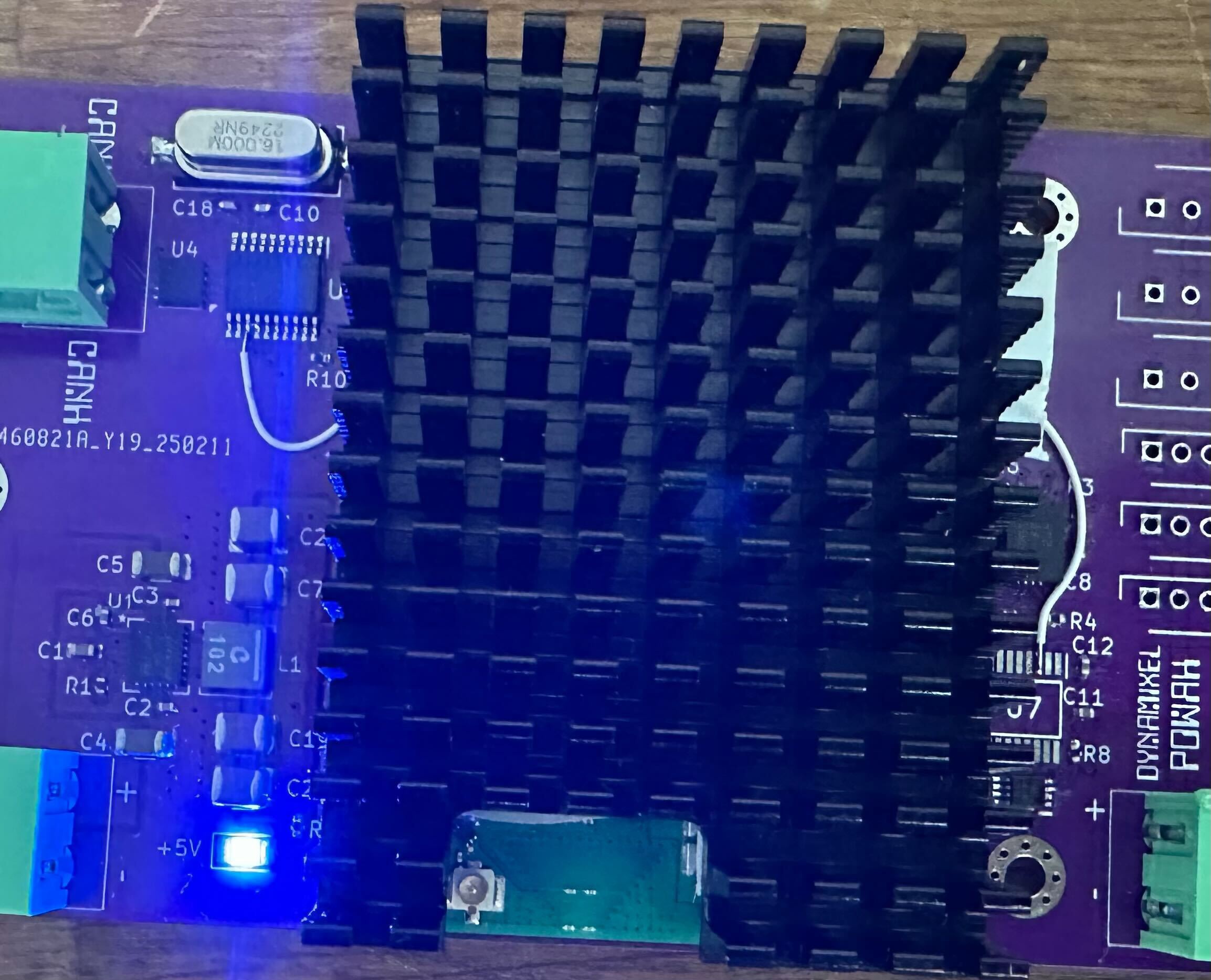
* MCP2515 CAN controller
* TJA1051 CAN transciever (The '51 has configurable I/O voltage reference)
* BNO055 IMU (NRND, but I will use it as long as it is available since it has 9 axis in one package and it is easy to use)

I'll update the project with schematics once I have a working first version :)

  • This thing actually works

    Hans Jørgen Grimstad04/15/2025 at 11:07 0 comments

    My normal approach when prototyping stuff is to dive into the schematic editor and cobble together functional blocks from past projects with stuff i found on the interwebs or from the "typical application circuit" section from a data sheet. You've probably been there. I don't really expect stuff to work on the first attempt, but I'm pretty satisfied if I can weed out all brainfarts on the second iteration.

    The Dynamixel servos I use (AX-12, MX-12, XL-320) are all half duplex serial devices. There are no dedicated TX/RX lines.

    Yesterday I started testing the half duplex UART circuit on the board. I am using uart0 together with a GPIO pin for controlling TX/RX. The GPIO pin and the RX/TX pins on the uart are routed through a level shifter and then to a NC7WZ241. This circuit is more or less equivalent to the Robotis U2D2 communication converter.

    For testing i wrote a small program in Go that manually constructs a ping packet and waits for a response. The default response timeout for the servos are typically 500 microseconds.

    Dynamixel protocol 1 is pretty straight forward. The PING packet looks like this:

    b[0] = 0xFF    // Header
    b[1] = 0xFF    // Header
    b[2] = byte(id) // target ID
    b[3] = 0x02    // length
    b[4] = 0x01    // ping instruction
    b[5] = ^(b[2] + b[3] + b[4]) //Checksum

    I tried three different serial libraries before I was able to reliably open up and use the serial port. github.com/tarm/serial turned out to be the winner.

    The program was cross compiled from my PC and SCP'ed over to the pi.

    And... 

    We got a ping response from servo id 1. Yaaay! :)

    It almost looks like this thing actuall works.

    PS. I noticed that the Xiaomi CyberGear motors currently are borderline unobtainium (black market pricing on the few that are listed on ebay). I don't know if these motors are discontinued by Xiaomi or not. I did contact a seller in Shenzen via Alibaba. He claimed that Xiaomi are still producing these, so we'll just have to wait and see. Please drop me a comment if anyone has any info on this.

    The CAN section on this board is not Cybergear specific, so it is not a big deal, but I really like these motors, since they are relatively cheap and also easy to control.

  • Happy Days!

    Hans Jørgen Grimstad04/11/2025 at 17:44 0 comments

    A couple of facpalms later and I have a glorious new revision of the board!

    Fixes in revision 1.2:

    • Correct wiring of the MCP2515 CAN Controller interrupt pin.
    • Correct wiring of the DXL_DIR signal that goes to the the NC7WZ241K8X buffer via a TXB level shifter (3.3V logic levels on the board and the Dynamixel servos require 5V logic for the half duplex data line).
    • Remapped I2C so it is using GPIO3 for SCL and GPIO2 for SDA.


    New features in revision 1.2:

    • Wired ethernet (makes life a bit easier for ad hoc connections / testing). This was also a nice excuse for me to familiarize myself with differential pair routing in KiCAD :)
    • Active PWM cooler (Added a JST BM04B-SRSS-TB 4 pin connector for 5V, GND, PWM and TACHO)
    • Mounting option for SMA connector / Antenna

    Initial testing is promising. Current status is as follows:

    • Both network interfaces are ok.
    • I2C is ok. IMU is detected.
    • SPI is ok.
    • CAN is ok.
    • Fan PWM control is ok.

    Next up is to verify that the Dynamixel side of the board is ok. It is basically the same circuit that I have used on several other boards, so I don't expect any surprises (famous last words... :))

    At some point I guess I'll have no choice, but to build a couple of demonstrator robots for the board (and maybe look into a realtime kernel if I run into strict timing requirements somewhere). My AX-12A based hexapod is an obvious choice for testing the board with Dynamixel servos. I havent decided on a CyberGear project yet. I biped would be fun, but that would get expensive real fast, so maybe I'll settle for a simple robot arm project (Maybe CyberGear joints + Dynamixel grippers ?) .

  • Making progress

    Hans Jørgen Grimstad03/27/2025 at 21:47 0 comments

    After fixing a typo in the pin numbering in the overlay and a newly introduced solder bridge between the int and SCK pin, I can now talk to the cybergear. 

    My overlay now looks like this:

    [cm5]

    dtparam=spi=on
    dtoverlay=dwc2,dr_mode=host
    dtparam=ant1
    dtoverlay=spi0-1cs,cs0_pin=8,sclk_pin=11,miso_pin=9,mosi_pin=10
    dtoverlay=gpio-pullup,gpiopin=5
    dtoverlay=mcp2515-can0,oscillator=16000000,cs_pin=8,sclk_pin=11,miso_pin=9,mosi_pin=10,interrupt=5

    (I have also disabled any configurations that might conflict with my SPI pinout)

    My TODO list so far consist of the following items:

    • Add a connection between the MCP INT pin and free GPIO on the CM5 header
    • Fix the Dynamixel side of the board (single node net for DXL_DIR signal)
    • (Not sure if this is necessary or not) Add a (NP) pullup option for the INT signal
    • (maybe) wired ethernet option (ssh over bad wifi can be rather frustrating)
    • 3.3V led indicator
    • Option for active PWM cooler
    • Break out a few more GPIO, 3.3V, GND and maybe I2C for future proofing
    • ...

    I can now start working on testing the IMU :)

  • Bodge wire FTW!

    Hans Jørgen Grimstad03/26/2025 at 21:01 0 comments

    I finally got around to doing some work on the board (Looks like I'm in for a second revision...)

    I changed the crystal to 16Mhz (and also changed the caps to two x 18pF). When I now do "sudo ip link set can0 up type can bitrate 1000000", I don't get an error and the board current increases by 100-150mA. Something just got enabled, right ?

    The bad news is that the compute module now crashes when I try to bring up the CAN interface. It crashes _hard_. No trace in any of the log files.

    Sooo,... I turned to my old friend - ChatGPT.

    Which after a brief chat (where I let it slip that I hadn't connected the MCP2515 interrupt pin to _anything_), kindly informed me that the kernel wouldn't be very happy bringing up can0 if that particular pin was left floating. Being interrupt driven and all...

    The natural next thing to do in such scenarios is to apply a bodge wire from the MCP int pin (#13) to any available GPIO pin on the controller. Of course I hadn't expose any additional GPIO on the board (or test pads for that matter).

    After having reviewed the schematic and layout, it also dawned on me that I had a single node net in there on one of the other ICs (I have to admit that I am somewhat disappointed in KiCad for not informing me about this when I ran ERC)

    But,...

    That also meant that I could remove the chip with the single node net (which also had to more pins that was connected to the compute module). TXB0106 b'Gone ! I now had exposed two pads and could repurpose one of the DXL_RX/TX signals.

    I chose the DXL_RX signal (pin 3 on U7) was routed to GPIO5 and then updated the boot overlay to:

    dtoverlay=mcp2515-can0,oscillator=16000000,cs_pin=8,sclk_pin=11,miso_pin=9,mosi_pin=8,interrupt=5

    After a reboot I then tried bringing up can0 with the following command (full bitrate and all :))

    sudo ip link set can0 up type can bitrate 1000000

    I got no errors and it didn't crash this time either. When checking ifconfig, i got this:

    can0: flags=193<UP,RUNNING,NOARP>  mtu 16
            unspec 00-00-00-00-00-00-00-00-00-00-00-00-00-00-00-00  txqueuelen 10  (UNSPEC)
            RX packets 0  bytes 0 (0.0 B)
            RX errors 0  dropped 0  overruns 0  frame 0
            TX packets 0  bytes 0 (0.0 B)
            TX errors 0  dropped 0 overruns 0  carrier 0  collisions 0

    Happy days :)

    I can now test the next thing, which is to send actual CAN frames to the CyberGear motor. If that works ok, I'll test out the IMU. If everything is ok up to that point, I'll spin a new revision with a fix for the missing INT and DXL_DIR signals. I can then proceed to also test the Dynamixel interface.

  • RTFMs

    Hans Jørgen Grimstad02/27/2025 at 19:30 0 comments

    I read chapter 2.6.1 "Alternative function assignments" in the "Raspberry Pi Compute Module 5" manual _carefully_ before deciding on the GPIO pin assignment in my schematic. I decided on using SPI4, I2C0 and UART2. Too bad I didn't read the rest of the manual. Especially the table where the clearly states that SPI4 is "slave only"

    Fortunately it seems that I can use SPI0 with the SPI4 pinout using some device tree magic. The following line in config.txt did the trick:

    dtoverlay=spi0-1cs,cs0_pin=8,sclk_pin=11,miso_pin=9,mosi_pin=8


    Next up was defining the overlay for the MCP2515

    dtoverlay=mcp2515-can0,oscillator=8000000,cs_pin=8,sclk_pin=11,miso_pin=9,mosi_pin=8

     Do you spot the second brain fart already ? (The Xiaomi Cybergears default to a bitrate of 1000000)

    Now I had to make sure that the mcp driver was loaded

    > echo "mcp251x" | sudo tee -a /etc/modules

    After a quick reboot, i checked dmesg

    hansj@cyber-1:~ $ dmesg | grep 2515
    [    4.277991] mcp251x spi0.0 can0: MCP2515 successfully initialized.

    Yaaaay - right...?

    Now it was tTime to bring up can0

    sudo ip link set can0 up type can bitrate 1000000
    Error: bitrate error: 33.3% too high.

    Wooops...

    Turned out I hadn't looked to carefully at the MCP2515 datasheet either, so I had selected a 8MHz crystal without thinking about the implications regarding the maximum bitrate the mcp could support given the frequency of the oscillator. I can do a bitrate of 500000, but not 1000000.

    This is fixable by changing the Cybergear bitrate using communication type 22 via another tool, but I decided to order some 16Mhz crystals from Mouser instead (along with some 22pF capacitors). I guess they will arrive in a couple of days.

  • CM5 first light - Leeroy Jenkins style

    Hans Jørgen Grimstad02/24/2025 at 21:35 0 comments

    The Raspberry Pi IO Board has been sitting on my shelf for a few weeks now. This evening, I finally got around to flashing two of the compute modules. This process is supposed to be rather easy, but I actually struggled a bit before i got it up and running

    It was rather nerve wracking powering up the controller board with the first CM5 mounted, but it did't blow up and I managed to get a shell via wifi. Happy days :)

  • Manual PCBA

    Hans Jørgen Grimstad02/23/2025 at 18:11 0 comments

    Just finished assembling two of the boards. So far, I have only tested the 5V power rail.  Power LED lights up and no detectable current draw withouth the CM5 in place. This is a good sign, since there is no smoke coming out and no shorts between power and ground anywhere. 
    My biggest worry was the tolerances of the CM5 connectors, but the footprint / placement seems to be ok. The module snapped into place without any problems.
    Next, I'll have to verify that the pinout is OK. Since I am going to use both SPI, I2C and UART + a couple of GPIO pins, it is entirely possible that I have made a mistake that will require a modification and a new revision (200 pins and mutually exlusive I/O function assignments is a recipe for future facepalms)

  • Fresh PCBs !

    Hans Jørgen Grimstad02/17/2025 at 20:13 0 comments

    Just got my prototype batch from JLC today.  I decided to include support for dynamixel AX-12 and XL-320 as well as the Cybergears. Next up - assembly and testing. I am NOT looking forward to aligning the CM5 100 pin connectors, though :|

View all 8 project logs

Enjoy this project?

Share

Discussions

Rich text editor

Similar Projects

Does this project spark your interest?

Become a member to follow this project and never miss any updates