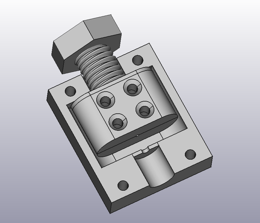
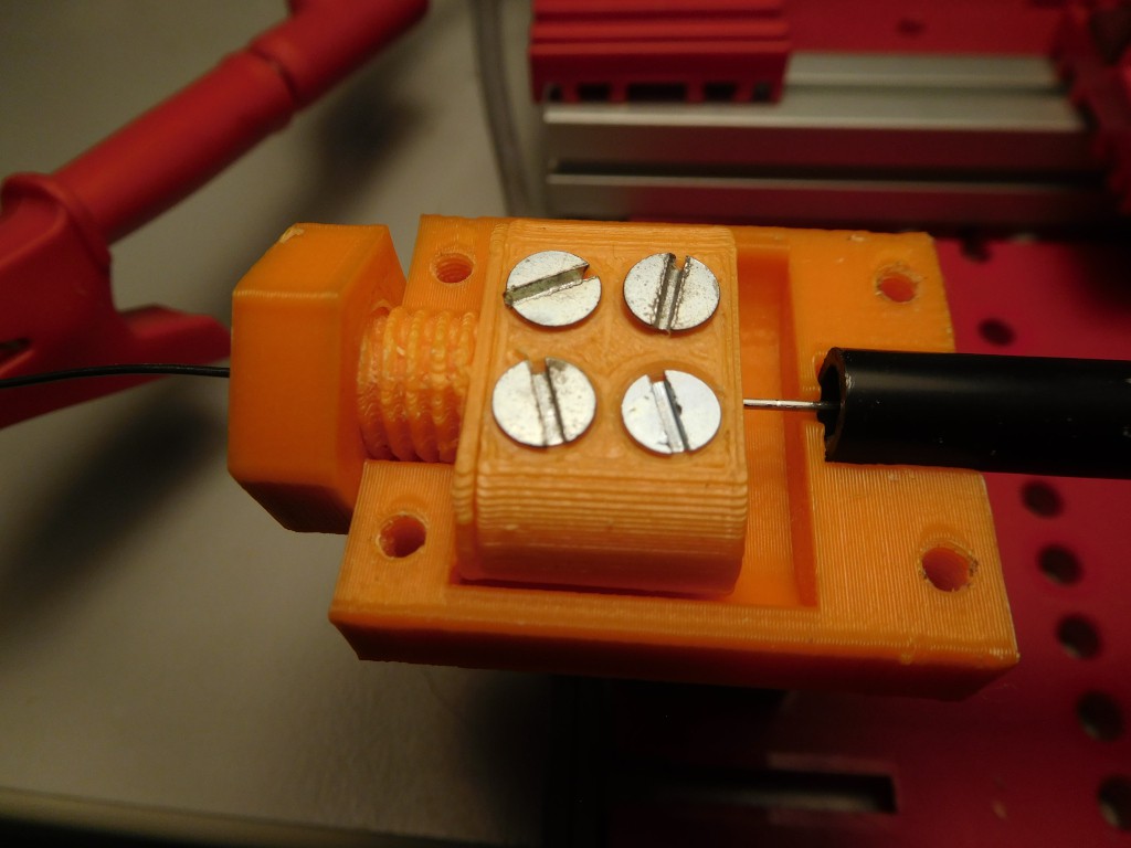
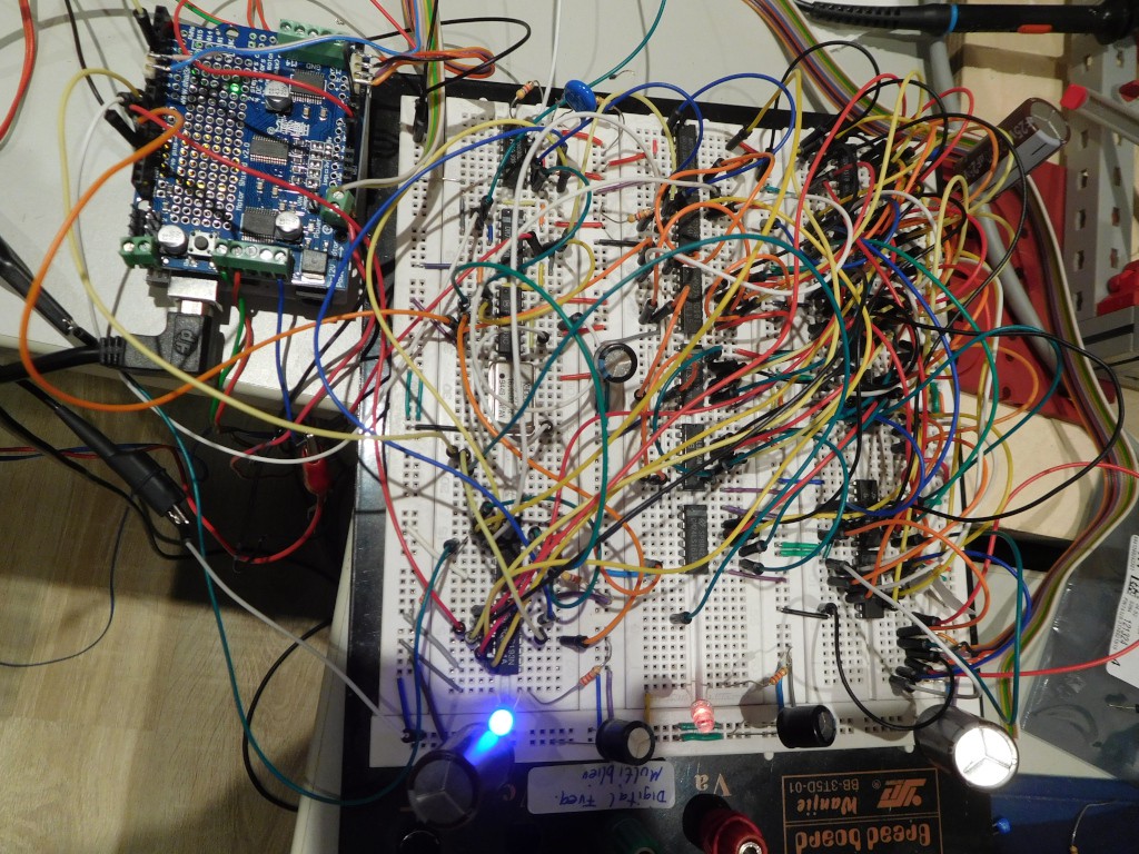
Here is now another time measurement device built with conventional TTL-Hardware.
Idea is to provide an understandable circuit without exotic hardware such as a CPLD.
The device works excellent and I prefer it to the measurements with Arduino-Uno.
It can measure up to 16 pulse time values a 16 Bit.
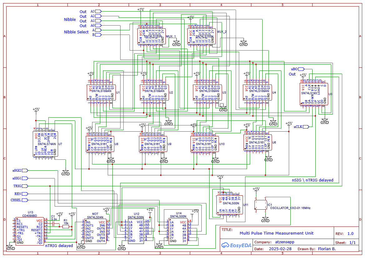
Here how it works:
The Measurement is engaged by setting EN (and nCLK) to High, Then the Channel is selected with CHSEL and an Excitation Pulse is triggered (TRIG).
The TRIG signal resets the 74LS193 index counter adressing the Storage cells.
With a delay Monoflop CD4089 the TRIG signal is delayed to reject Signal impulses coming directly after the excitation.
The delayed Trigger signal resets a RS-Flip flop and clock pulses are fed to the synchronous 74LS161 counters.
The negative Signal of an incoming Signal stores the acutal counter values into 4-Bit 74LS198 TTL-Rams addressed by the index counter.
The Signal pulse increments the index counter. When the counter overruns the Carry will stop the measurement by setting the RS-Flip-Flop which disables the time measurement counters are disabled.
The counter can also be stopped by the Microcontroller by setting EN to LOW to terminate measurement when less than 16 signals are registered.
Now the Microcontroller can read out the values by decrementing the index counter with nCLK, observing BO which indicates a Zero-Transition as a LOW value.
Each counter value is read nibble by nibble addressing it with A,B. The nibble values appearing at A0..A3. Microcontroller has to invert these values because 74LS189 is inverting the values.
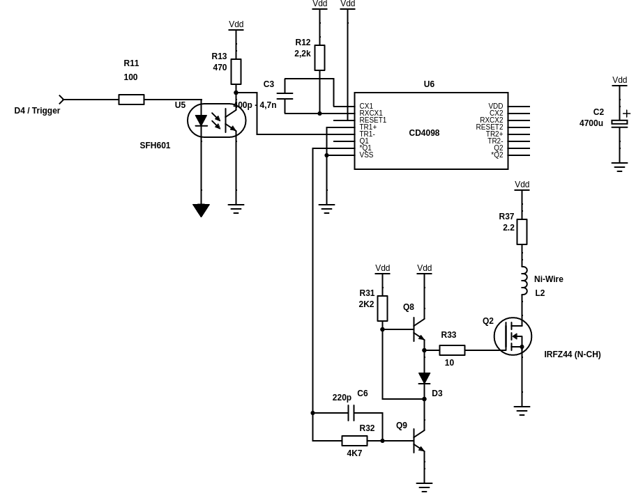
Direct driving the Mosfet from the CMOS-Monoflop is not optimal as the capacity of the gate deteriorates the pulse somewhat. It seems that the usual way would be to use a gate driver IC. But before ordering one I wanted to try it out first with a discrete circuit from Mr. T's: 3 Simple MOSFET Drive Circuits
I opted for the "Cascode-Driver", which works very well in my case. It also works for a High-Side P-Channel Mosfet when changing npn to pnp transistors, reversing the polarity and driving the circuit using the non inverting Output of the Monoflop.
Additionally I also added a small resistor in series with the wire to decrease the impulse load of the power supply.
Goal is to have only a "wavelet" with one prominent peak.
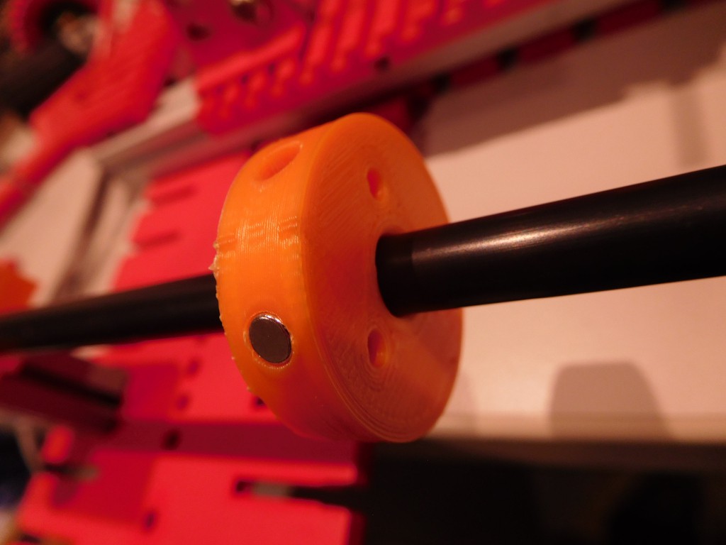
Cursor Magnet orientation and strength
stronger magnets can create larger signal amplitudes. But also the orientation of the magnets are relevant.
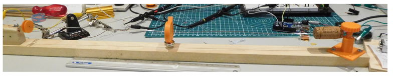
I achieved best results with Nd-magnets positioned around the tube with magnet poles showing in the same direction namely towards the wire. The pucture above shows the new magnet holder for up to 6 4mm Nd-Magnets.
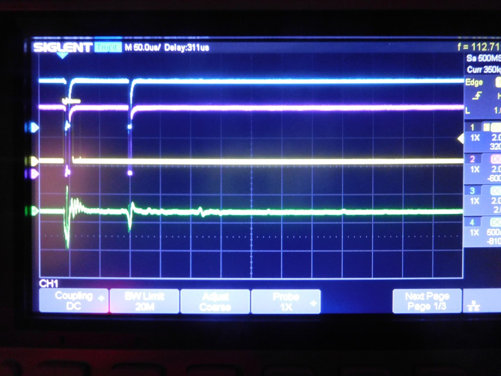
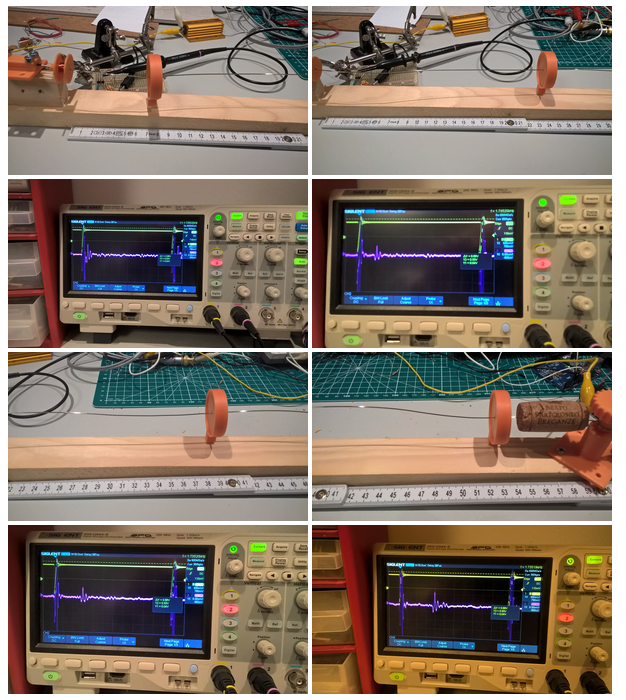
With three magnets loaded and damping at both ends I am getting a very strong and clear single wavelt pulse. The relfection (right) is below the comparator threshold:
Receiver Coil
Number of windings of the reciever coil. The more windings the larger the signal. However with larger number of turns also the direct response of the excitation signal prolongs. I am using 700-800 Windings. But I will check if 1000 Windings will yield a better signal.
Amplifier Circuit
The amplifier is critical. Especially the RC filter between the first and the second Amplifier stage is critical.
Comparator Circuit
Adding small hysteresis by a feedback resistor to the + input will suppress ringing oscillations
A convenient way to measure the pulse times can be accomplished with Arduino UNO's Input Change interrupt of Timer1. With this method no extra counter hardware or a CPLD / FPGA is required.
The Counter of Timer1 is captured when a pulse is detected at a specific input, namely Pin D8. This limits the usage of this method a bit with the traditional Arduino Motor shields which utilize this pin for Motor Break.
Howver for the I2C controlled Quad-Motor shields such as Adafruit Motorshield V2 this is no restriction.
Description:
Time Measurement with Arduino UNO's TIMER1 and Input Capture on Pin 8 Signal containing negative Start and Stop pulses (High->Low)
Time measurement takes time between Start and Stop pulse.
Direct after Trigger the Excitation pulse generates an immediate response with lots of unwanted SIG pulses which we need to skip. The usual time in my setup are 40us. In my first attempts with software delays I observed some jitter. Therefor I decided to introduce a Hardware Delay with a CD4098 Monoflop. This is the Delay Gate Circuit which is introduced in the Build Log.
The Monoflop is simultaneously triggerd with the Excitation Pulse (TRIG). This delayed inverted Trigger signal nGTRIG is combined with the Raw signal SIG from the Amplifier/comparator with a logical AND:
nGTRIG and SIG
Ideally we will get one nGTRIG signal and one or more SIG. .
Signals SIG active Low Raw signal form Amplifier / Comparator TRIG D4 active High (SEL1) Triggers Excitation Circuit and Delay Gate nGTRIG active Low Delayed Trigger Pulse SIG' D8 active Low SIG = GTRIG and SIG
For more position sensors we can introduce a 2:1 Multiplexer which is controlled by:
The following measure routine can handle 2 channels. After emitting a Trigger pulse it waits some time (until we are sure the measurement is over) and analyzes the pulses. The code snippet below shows also some continuous averaging. This function is blocking and emits pulses until a non zero value is registrered.
Note: For a well damped wire (Rubber clamps and Hot glue) only one SIG pulse is seen which can be easily evaluated. If more than one SIG pulse is detected, advanced analyzers such as the Quartet analyzer described before can be used.
Here a signal image of a single torsion wave pulse inm a well damped configuration:
This image shows a linearity check of the measurements with the described method:
To build a Magnetostrictive sensor rig you do not need much. A wire clamp and eventually a wire tensioner, a coil and a moving magnet are enough. Of course you need the electronics described above. Here as damper a wine cork is used. Coil, magnet holder and tensioner can be found here: Parts for Basic Magnetostrictive Position Sensor
In this configuration stronger damping is established. Here no quartet pulses are seen but solely the main pulse. With this setup the readout is very easy as only one puls has to be evaluated. However in this setup the position determination works only if distance of manget to coil is larger than 7cm.
My initial approach for time measurement was to utilize the Input capture feature of the Arduino UNO's timer1.
Another option to measure the time is by utilizing a CPLD. With this I can measure up to signals of up to 4 signals. We can apply digital delays and signal debouncing. I am using an older but hobbyist friendly 5V tolerant and thus "Arduino compatible" EPM7128SLC84-15 for this. This device limits the acquisition to 4 Pulses with a maximum time count of 13 bits. With a more powerful device more bits and more signals can be measured but for my experiments this is just enough.
The following VHDL code implements such a time measurement counter.
A measurement is initiated with a High-Low-Transition of the TRIG Signal. This event will start a Time Counter. that is clocked with externally provided 16MHz clock pulses at COUNT_CLK. After a time delay it accepts Low signals at input SIG and records the time. Up to 4 signals can be measured with a resolution of 13 bits.
The Arduino reads the counter value in chunks of 4 bit nibbles adressed by A0 and A1. The data is available at the Data port D0..D3. Before the first read out READ_RES is set to Low and a negative Clock pulse is applied at READ_CLK. After all nibbles are read the read counter can be advanced by setting READ_INC to High and applying another READ_CLK pulse. Values are combined in the Arduino sketch.
Signals are:
- COUNT_CLK - Input for external clock Into CPLD
- TRIG - Input for Trigger pulse
- SIG - Input for digitized Signal pulse
- READ_CLK - Clock Input for read interface
- READ_RES - Reset Input for read interface (to reset to first measured signal)
- READ_INC - Increment Input for read interface (to advance to next measured signal)
- A0, A1 - Nibble select input to select the counter nibbles
- D0,D1,D2,D3 - Data output port to transmit data to the Arduino
    library IEEE;
    use IEEE.STD_LOGIC_1164.ALL;
    use IEEE.NUMERIC_STD.ALL;

    library IEEE;
    use IEEE.STD_LOGIC_1164.ALL;
    use IEEE.NUMERIC_STD.ALL;

    entity TimeMeasurementCounter is
         generic (
            data_width : integer := 13
         );
         Port (
              COUNT_CLK : in STD_LOGIC;                -- 16 MHz clock for time measurement
              READ_CLK : in STD_LOGIC;               -- Clock signal for micro controller read out
              READ_RES : in STD_LOGIC;               -- READ_RES='0' + one READ_CLK resets read counter
              READ_INC : in STD_LOGIC;               -- READ_INC='1' + one READ_CLK incements read counter
              TRIG : in STD_LOGIC;                   -- start the measurement
              SIG : in STD_LOGIC;                         -- signals 1-0-Transition to be measured
              A : in STD_LOGIC_VECTOR (1 downto 0);  -- Nibble address
              D : out STD_LOGIC_VECTOR (3 downto 0)  -- DAta port for nibble
         );
    end TimeMeasurementCounter;

    architecture Behavioral of TimeMeasurementCounter is
         signal TC : STD_LOGIC_VECTOR (data_width downto 0) := (others => '0');     -- Timer Counter
         type reg_array is array (0 to 3) of STD_LOGIC_VECTOR (data_width downto 0);
         signal  R : reg_array := (others => (others => '0'));              -- Register for measured times
         signal  RC : STD_LOGIC_VECTOR (2 downto 0) := (others => '0');     -- Index for registration process
         signal  RC2 : STD_LOGIC_VECTOR (1 downto 0) := (others => '0');    -- Index for readout process
         signal  sig_state: STD_LOGIC := '0';                               -- state is 1 to indicate that a signal was registered
                                                                                                  -- will go back to 0 when SIG gets back to 1
         constant DEAD_TIME : INTEGER := 80;                                -- Pulses registered after 40us * 16MHz
         constant DEGLITCH_TIME : INTEGER := 250;                                -- Pulses registered after 40us * 16MHz
         signal TCOLD : STD_LOGIC_VECTOR (data_width downto 0) := (others => '0');
    begin

         -- Counter and Signal registration process
         process (COUNT_CLK,SIG,sig_state)

         begin
              if rising_edge(COUNT_CLK) then
                    if  TRIG = '0'  then             -- Initialization and start of measurement
                         TC <= (others => '0');
                    else                                        -- Counting
                          TC <= std_logic_vector(unsigned(TC)+1);
                    end if;
                end if;
         end process;

         process (TRIG,SIG)
          variable rccounter : unsigned (2 downto 0);
         begin
                if  TRIG='0' then
                    RC <= (others => '0');
                    for i in 0 to 3 loop
                      R(i) <= (others => '0');
                    end loop;
                    TCOLD <= TC;
                elsif falling_edge(SIG) and (unsigned(TC)-unsigned(TCOLD)) > DEGLITCH_TIME and unsigned(TC) > DEAD_TIME  then  -- Signal registration
                    rccounter := unsigned(RC);
                    if rccounter < 4 then   -- register up to 4 signals
                      R(to_integer(unsigned(RC))) <= std_logic_vector(unsigned(TC));
                      rccounter := rccounter+1;
                      RC <= std_logic_vector(rccounter);
                      TCOLD <= TC;
                    end if;
                end if;

         end process;


         -- Readout process
         process (READ_CLK)                    --- is clocked with a READ_CLK
        --        variable X : STD_LOGIC_VECTOR (15 downto 0) := (others => '0');
         begin
          if falling_edge(READ_CLK) then
             if READ_RES='0' then                    --- Reset the Read Counter
                  RC2 <= (others => '0');
             elsif READ_INC ='1' then                --- Increment Read Counter
                  RC2 <= std_logic_vector(unsigned(RC2) + 1);
              end if;
            end if;
          --- Copy adressed Nibble into D
          -- X(data_width downto 0) := R(to_integer(unsigned(RC2)));
          -- D <= X(4 * to_integer(unsigned(A)) + 3 downto 4 * to_integer(unsigned(A)));
            case A is
                when "00" =>
                     D(3 downto 0) <=     R(to_integer(unsigned(RC2)))(3 downto 0);
                when "01" =>
                     D(3 downto 0) <=     R(to_integer(unsigned(RC2)))(7 downto 4);
                when "10" =>
                     D(3 downto 0) <=     R(to_integer(unsigned(RC2)))(11 downto 8);
                when "11" =>
                     D(0 downto 0) <=     R(to_integer(unsigned(RC2)))(12 downto 12);
                     D(3 downto 1) <= "000";
                when others =>
                     D <= "0000";
            end case;
         end process;

    end Behavioral;
The following Code snippet shows how read-out is done in Arduino:
longreadCounterNibble(int n)
{
long x = 0;
switch(n)
{
case0: digitalWrite(AD0,0); digitalWrite(AD1,0); break;
case1: digitalWrite(AD0,1); digitalWrite(AD1,0); break;
case2: digitalWrite(AD0,0); digitalWrite(AD1,1); break;
case3: digitalWrite(AD0,1); digitalWrite(AD1,1); break;
} delayMicroseconds(10);
digitalWrite(READ_INC,LOW);
digitalWrite(READ_RES,HIGH);
delayMicroseconds(10);
clockLow(READ_CLK);
digitalWrite(READ_INC,LOW);
if(digitalRead(A0)) x |= 1;
if(digitalRead(A1)) x |= 2;
if(digitalRead(A2)) x |= 4;
if(digitalRead(A3)) x |= 8;
return x;
}
longreadCounter(int ch)
{
long c = 0;
// |
c = readCounterNibble(0) | (readCounterNibble(1) << 4 ) | (readCounterNibble(2) << 8) | (readCounterNibble(3) <<12);
return c ;
}
The measurement values are registered in 4 channels and analyzed in a "Quartet tracker".
The following snippet shows the "Quartet tracker" which tracks a complete or incomplete quartet of pulses.
#define NMEAS 4#define AUTOTUNE_DT#define AUTOTUNE_TM
typedef struct {
long val;
long lastval;
int upd;
} Channel;
typedef struct {
long dt,tm;
Channel * channels;
int astate=0;
long value;
} Measurement;
/*
* Quartett-Tracker
*/
int analyze4( long * signal, Measurement *meas)
{
int signal_length;
long value=0;
int i;
signal_length=i;
if (meas->astate == 0 && signal_length >= 4) { // Capture modefor (int i = 0; i < signal_length; i++) {
for (int j = i + 1; j < signal_length; j++) {
if (signal[i] > 0 && signal[j] > 0) {
if (abs(signal[j] - signal[i] - meas->dt) < EPS) {
if (signal[i] < meas->tm && signal[j] < meas->tm) {
meas->channels[0].val = signal[i];
meas->channels[1].val = signal[j];
meas->astate = 1;
}
if (signal[i] >= meas->tm && signal[j] >= meas->tm && abs(2 * meas->tm - meas->channels[0].val - signal[j]) < EPS) {
meas->channels[2].val = signal[i];
meas->channels[3].val = signal[j];
if (meas->astate == 1) {
meas->astate = 2;
//printf("Locked at %d\n",t);
}
}
}
}
}
}
if (meas->astate != 2) {
for (int i = 0; i < 4; i++) {
meas->channels[i].val = 0;
}
meas->astate = 0;
}
} elseif (meas->astate == 2) { // Tracking mode
backup(meas->channels);
int k = -1;
for (int j = 0; j < 4; j++) {
long delta=10000;
// Assign best matching signals to channelsfor (int i = 0; i < signal_length && signal[i] !=0; i++) {
if (abs(meas->channels[j].lastval - signal[i]) < EPS2) {
int found=0;
// avoid double assignmentfor(int p=i-1; p>0; p--)
{
if( meas->channels[p].val==signal[i] )
{
found=1;
}
}
if( found==0 )
{
if((i<2 && signal[i]<meas->tm) ||(i>1 && signal[i]>=meas->tm)) {
if( meas->channels[j].upd==0)
{
meas->channels[j].val = signal[i]; // channel not updated => assign Signal value
meas->channels[j].upd = 1; // mark updated
k = j;
}
else// channel already updated => assign Signal if it is nearer to last value:
{
long ndelta = abs(meas->channels[j].lastval - signal[i]);
if( ndelta < delta) // signal is closer to last value
{
meas->channels[j].val = signal[i]; // assign signal value
meas->channels[j].upd = 1;
k = j;
delta=ndelta; // this is now the best assignment
}
}
}
}
}
}
}
// Autotune dt and tm#ifdef AUTOTUNE_DTif(meas->channels[0].upd==1 && meas->channels[1].upd==1)
{
long dtn = meas->channels[1].val - meas->channels[0].val;
if( abs(meas->dt - dtn) < EPS)
meas->dt = meas->dt *0.6 + dtn*0.4;
}
if(meas->channels[3].upd==1 && meas->channels[2].upd==1)
{
long dtn = meas->channels[3].val - meas->channels[2].val;
if( abs(meas->dt - dtn) < EPS)
meas->dt = meas->dt *0.6 + dtn*0.4;
}
#endif#ifdef AUTOTUNE_TMif(meas->channels[0].upd==1 && meas->channels[3].upd==1)
{
long tmn = 0.5*(meas->channels[0].val + meas->channels[3].val);
if( abs(meas->tm - tmn) < EPS)
meas->tm = meas->tm *0.6 + tmn*0.4;
}
if(meas->channels[0].upd==1 && meas->channels[1].upd==1)
{
long tmn = 0.5*(meas->channels[0].val + meas->channels[1].val);
if( abs(meas->tm - tmn) < EPS)
meas->tm = meas->tm *0.6 + tmn*0.4;
}
#endifif(debugmode==1)
{
//Serial.print(" DT:"); Serial.print(meas->dt); Serial.print(" "); // Serial.print(" TM:"); Serial.print(meas->tm); Serial.print(" ");
}
if (k >= 0) {
// Reconstruct the missign signals:for (int j = 0; j < 4; j++) {
if (j != k) {
if (k == 0) {
if (j == 1 && meas->channels[j].upd == 0) {
meas->channels[j].val = meas->channels[k].val + meas->dt;
}
if (j == 2 && meas->channels[j].upd == 0) {
meas->channels[j].val = 2 * meas->tm - meas->channels[k].val - meas->dt;
}
if (j == 3 && meas->channels[j].upd == 0) {
meas->channels[j].val = 2 * meas->tm - meas->channels[k].val;
}
} elseif (k == 1) {
if (j == 0 && meas->channels[j].upd == 0) {
meas->channels[j].val = meas->channels[k].val - meas->dt;
}
if (j == 2 && meas->channels[j].upd == 0) {
meas->channels[j].val = 2 * meas->tm - meas->channels[k].val;
}
if (j == 3 && meas->channels[j].upd == 0) {
meas->channels[j].val = 2 * meas->tm - meas->channels[k].val + meas->dt;
}
} elseif (k == 2) {
if (j == 0 && meas->channels[j].upd == 0) {
meas->channels[j].val = 2 * meas->tm - meas->channels[k].val - meas->dt;
}
if (j == 1 && meas->channels[j].upd == 0) {
meas->channels[j].val = 2 * meas->tm - meas->channels[k].val;
}
if (j == 3 && meas->channels[j].upd == 0) {
meas->channels[j].val = meas->channels[k].val + meas->dt;
}
} elseif (k == 3) {
if (j == 0 && meas->channels[j].upd == 0) {
meas->channels[j].val = 2 * meas->tm - meas->channels[k].val;
}
if (j == 1 && meas->channels[j].upd == 0) {
meas->channels[j].val = 2 * meas->tm - meas->channels[k].val + meas->dt;
}
if (j == 2 && meas->channels[j].upd == 0) {
meas->channels[j].val = meas->channels[k].val - meas->dt;
}
}
}
}
}
else
{
// astate=0;
}
}
// if(debugmode==1) printc(meas->channels);
value= meas->channels[1].val;
/**
* Fallback für unlocked
*/if(meas->astate==2 || meas->channels[1].upd)
{
value= meas->channels[1].val;
}
elseif(meas->channels[2].upd)
{
value = 2*meas->tm-meas->channels[2].val;
}
elseif(meas->channels[3].upd)
{
value= 2*meas->tm-meas->channels[3].val -meas->dt;
}
elseif(meas->channels[0].upd)
{
value=meas->channels[0].upd+meas->dt;
}
//if(debugmode==1)// Serial.print(" STATE:"); Serial.print(meas->astate);
meas->value=value;
return value;
}
How does it work?
The signal must be a quartet of 2 doublets, one original and one reflected.
Pulses are assigned to the matching quartet pulses. When moving the magnet away from the receiver coil the times of the first dublet will rise and the times of the second one will decrease.
Note:
1. The quartet tracker requires initially one quartet for locking in. Once locked, individual signals may be missing. The quartet tracker assigns the measurements to the respective peak channel and reconstructs missing signals. No values are output before locking. To compensate the Arduino Sketch has a analyze1 method which analyzes only the first or second pulse.
2. The DT and TM values must be determined once and stored in the program. For determination, Printmode (with p) and Debug-Mode (with d) must be activated.
From the outputs: VAL:<val> X1:<T1> X2:<T2> X3:<T3> X4:<T4>
DT: Distance of the peaks in a doublet: DT = <T2>-<T1> = <T4>-<T3>
TM: "Length" of the wire: <T3>=2TM-<T2> or <T4>=2TM-<T1>
Issues:
DT depends on the coil position.
TM depends on the length of the sensor.
No values may be output before locking.
Ensure good shielding of the lines to the coil.
If jumps or waves occur, DT or TM may not be set correctly.
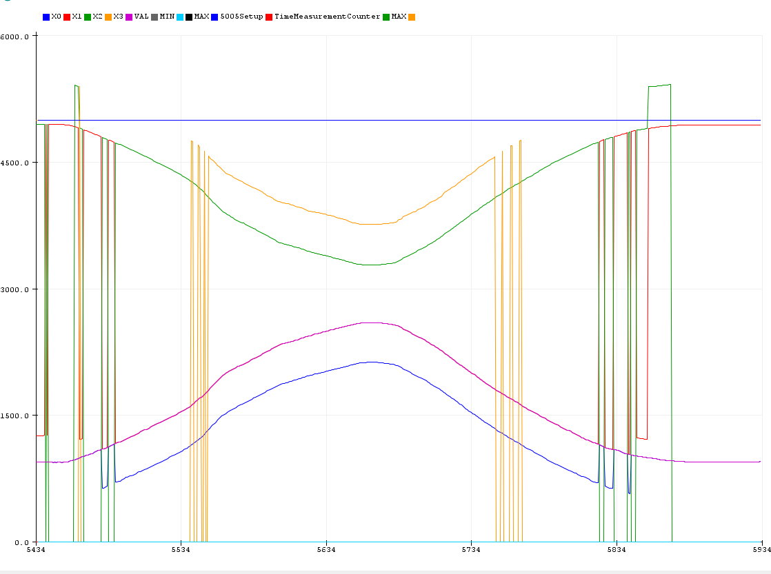
Here you can see how the Quartet Analyzer is reconstructing incomplete Quartets. In the middle time range all four signals are present. However the analyzer can reconstruct the VAL-signal (magenta) reliably even if raw signals are missing.
 Florian B.