Close
0%
0%

Magnetostrictive Position Sensor

Hard- and Software for a position measurement sensor with a magnet and a magnetostrictive wire.

Public Chat
Similar projects worth following
Magnetostrictive position sensors are commonly used in industry because of absolute and contactless position measurements. They make use of the creation of mechanical torsion waves triggered by an electrical current pulse through a magnetostrictive wire at the position of a moveable magnet.

From the time delay between the current pulse and the signal of the torsion wave induced in a pick-up coil the distance to the magnet can be determined.

The details are described in:
https://de.wikipedia.org/wiki/Magnetostriktiver_Wegaufnehmer

Although the principle is long known and well described I could not find any maker projects.
My work so far and the electronics are explained in detail in ft-pedia 04/2024.


The 3D parts introduced here for creating a PVC-tube-housed sensor are published on Thingiverse. There also the software can be found. Eventually I will create a github repository.

You can build such a sensor with a "free" wire without the tubing assembly

Do you want to build a Magnetostrictive Position Sensor as described in: https://de.wikipedia.org/wiki/Magnetostriktiver_Wegaufnehmer

Working principle

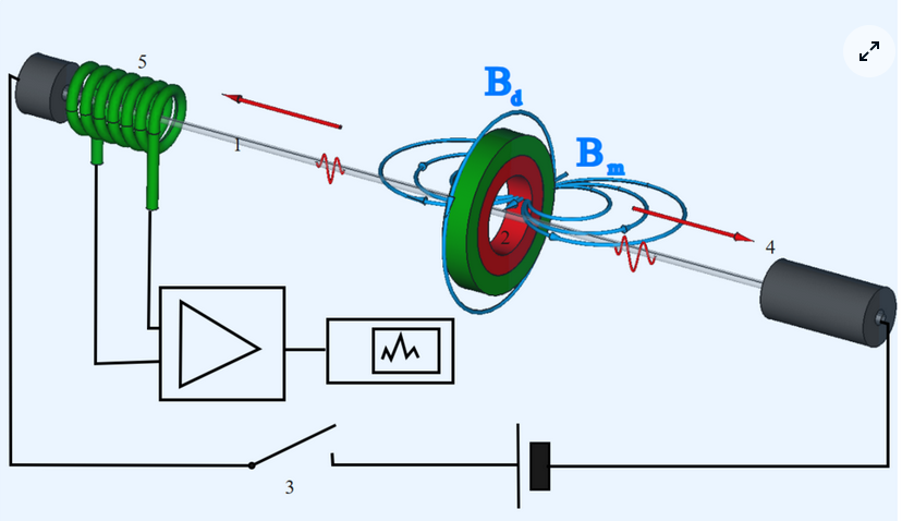
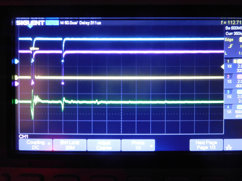
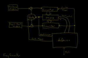
In short: A current pulse will initiate a torsion wave along a magnetostrictive wire at the position of a moving cursor magnet. The travelling torsion wave generates a signal in a receiver coil. From the time between current pulse and the signal pulse the position of the magnet (the distance between receiver coil and magnet) can be determined.
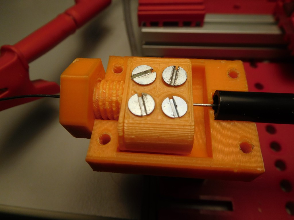
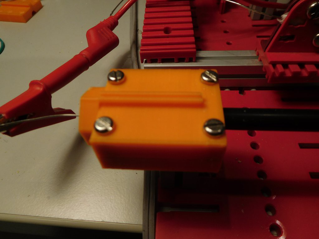
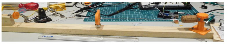
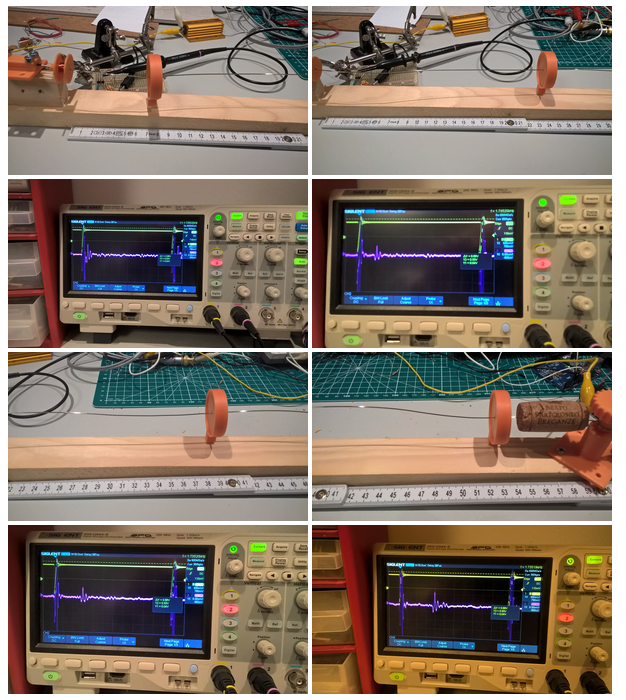
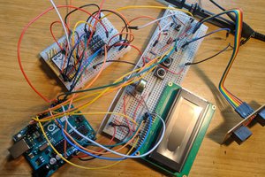

First prototype:


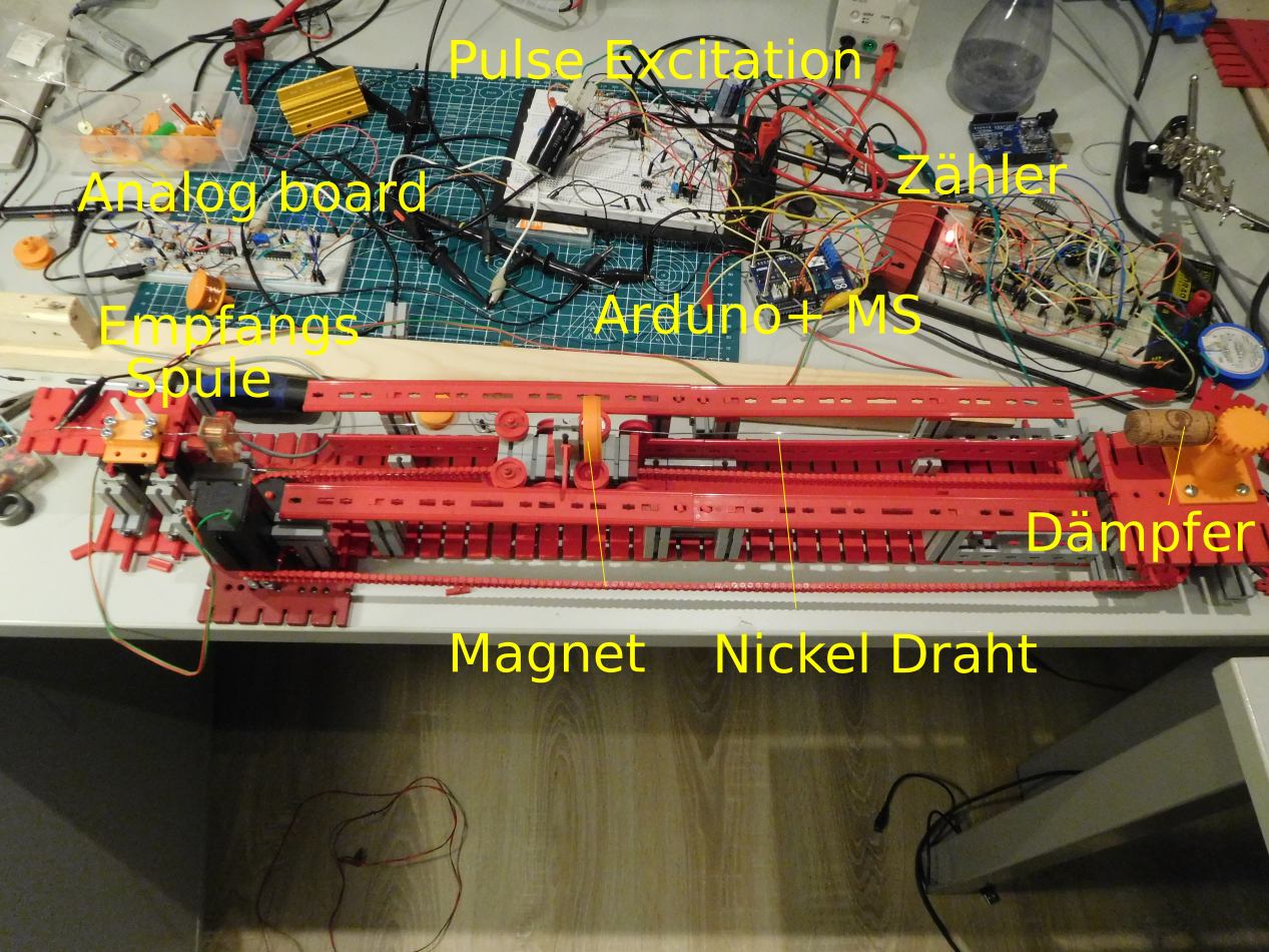
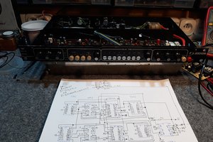
Tubed Magnetostrictive Position Sensor:

Carousel image representing the 3D design. Either an user-provided picture or a 3D render.Carousel image representing the 3D design. Either an user-provided picture or a 3D render.

Resources

On Thingiverse is a set of parts to build a Magnetostrictive Position Sensor. With this sensor you can measure the position of a magnet sliding along a PVC tube surrounding a magnetostrictive Nickel wire. You can use it to build a linear servo with a DC motor. The sensor is scalable as working range depends on the length.

The proposed 3D fittins are compatible with fischertechnik construction system. It consists of following parts:

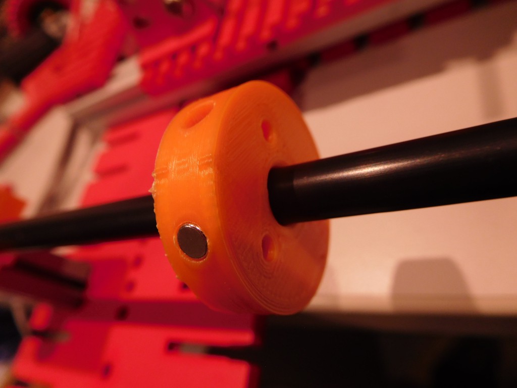
  1. Magnet Holder for Ring magnet
  2. End clamps (you need 4 pieces)
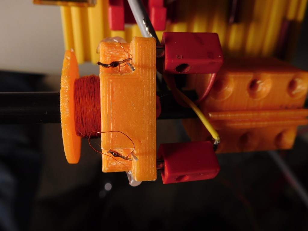
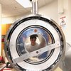
  3. Coil body
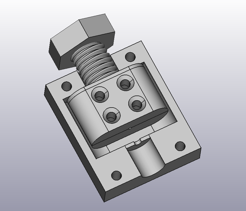
  4. Connector block for coil
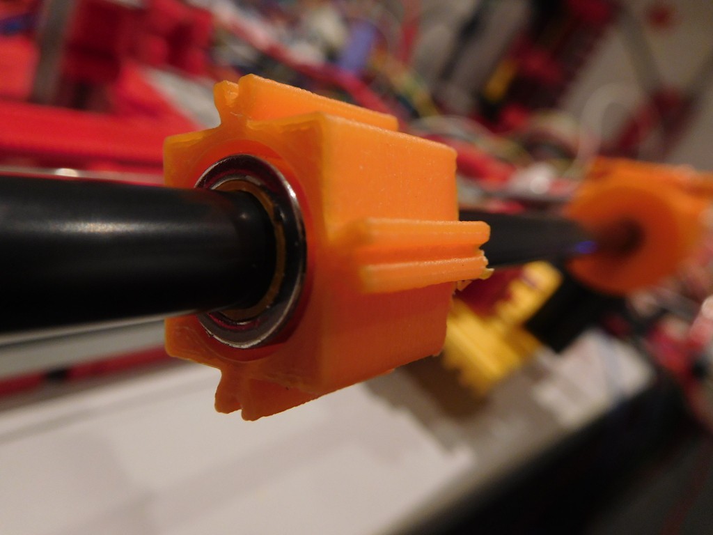
  5. Wire guide (print it upright with 0.1mm resolution, supports from build plate and large brim)
  6. Coil holder block for Fsichertechnik (part that can be used to mount coild to the Fischertechnik system if no tube is used)

To build this sensor followng additional parts and components are needed:

  • Nickel or NiFe wire (for heating applications) , Diameter: 0.8mm, Length: 60cm (for a 50cm sensor, but longer wires should be possible)
  • Nd Ring Magnet: Outer diameter: 12 mm, inner diameter, 8.5 mm, height: 4mm (I used: fix-o-moll Neodym Magnete Ringe 12mm silber )
  • PVC housing tube, Outer diameter: 7mm, Inner diameter: 5mm, Length 50cm (You can chose your desired length; It might be possible to use Aluminium tubes)
  • 12 x M3-Screws with sink head:, Length 10-15mm
  • Power Supply for excitation puilse: 10-20V
  • Separate Power Supply for analog electronics: 5-10V (Deriving Voltage from excitation power supply with an additional regulator should be possible)
  • Cu-Wire: 0.1-0.3 mm, for 800 Windings
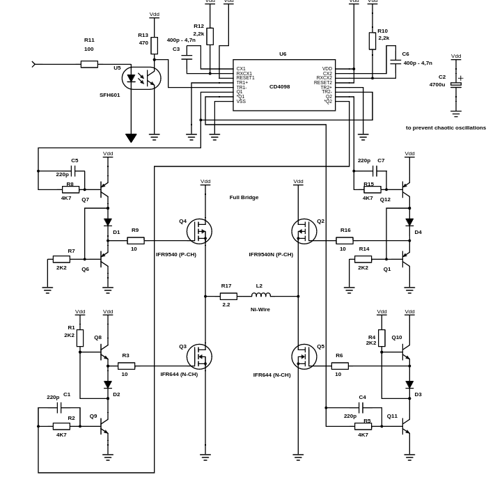
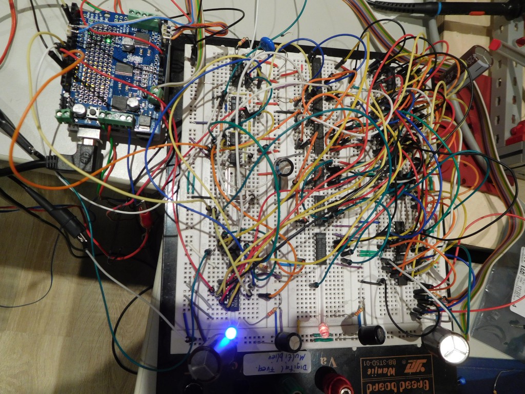
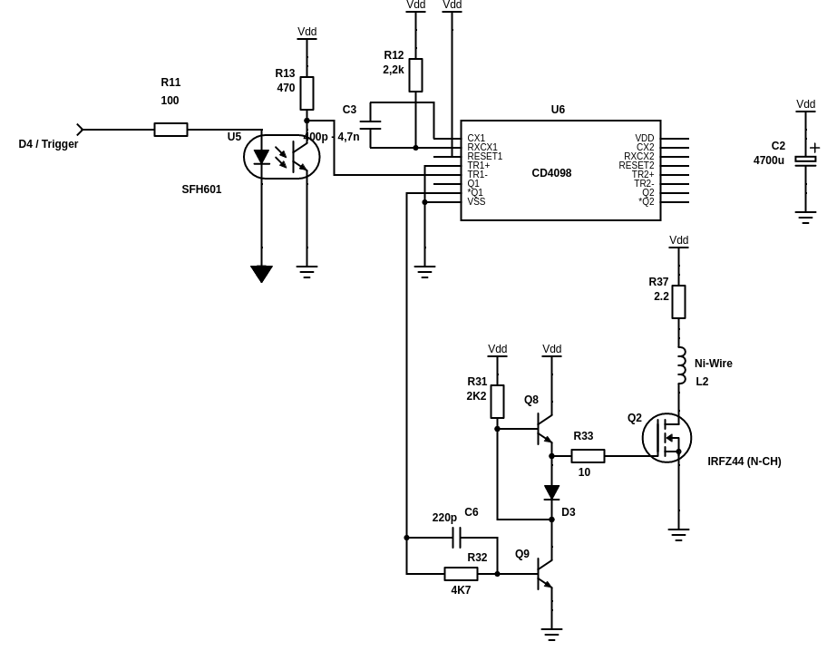
  • Exciter-Circuit with a good Power-Mosfet (*)
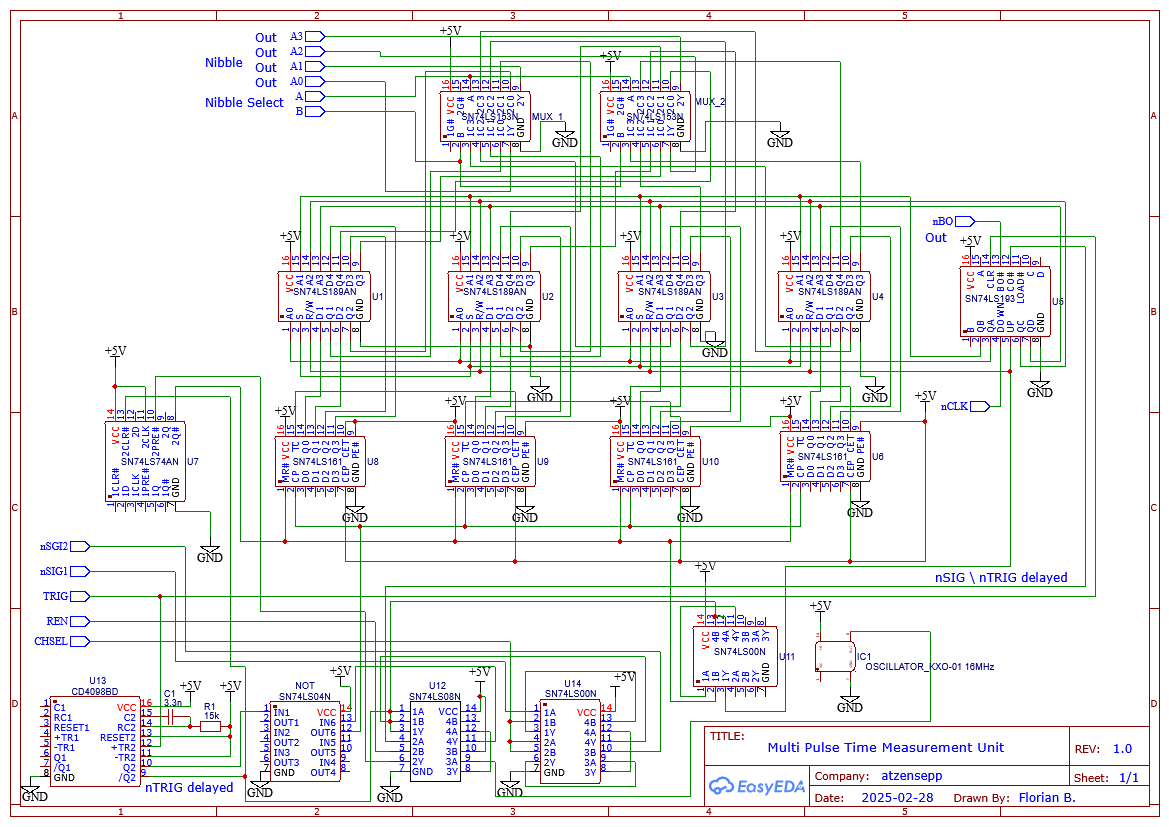
  • Analog Circuit (*)
  • Gate Circuit
  • Selector-Circuit
  • Arduino Uno (*)
  • Arduino Software

*: The princible and the sensor electronics is described in ft-pedia 2024/4: https://ftcommunity.de/ftpedia/2024/2024-4/ftpedia-2024-4.pdf

FreeCAD-File to adjust the fittings and an experimental Arduino-Sketch are included

Hints
  • Excitation Voltage (good value: 18V)
  • Excitation Pulse Duration (too long will cause ringing, too short will give too small signal)
  • Capacitive coupling between first and second amplifier stage 175pF followed by 10K to GND
  • Permanent Magnetization of the Nickel wire in the neighborhood of the receiver coil can occur and deteriorate signal recovery. Clean by moving a strong magnet along the wire
  • Contact of the wire with the tube wall should be avoided. Contacts can damp the signal or create errornious signals
  • Wire should be straight without bends and knicks
  • Gate circuit: Sufficient delay between excitation pulse and first signal (e.g. 40us)
  • LM311 Comparator can generate ringing oscillations. Pull-Up-Resistor must not be too small. 10k or 20k are ok.
  • Comparator ringing can be reduced by feeding back output signal to positive input of the comparator. This will create a hysteresis. (I used 65k between Pin 2 and 7)
  • Some switching power supplies inject a significant noise floor such that no reliable measurement is possible.
  • Some PWM driven Motors can also give rise to false signals. proper shielding helps.

TimeMeasurementCounter.ino

Arduino Sketch for Time Measurement with CPLD and Quartet Analyzer

ino - 15.40 kB - 02/07/2025 at 18:21

Download

Magnetostrictive_Quartet_Analyzer.ino

Arduino Sketch for Time Measurement with input capture feature of Timer1 and Quartet Analyzer

ino - 44.60 kB - 02/07/2025 at 15:25

Download

MTS-Spulenkoerper2.FCStd

FreeCAD file for tubed Magnetostriction Sensor

x-zip-compressed - 2.52 MB - 02/07/2025 at 15:16

Download

TimeMeasurementCounter.vhdl

VHDL file for Time Measurement Counter

vhdl - 4.08 kB - 02/07/2025 at 15:12

Download

TimeMeasurementCounter.dpf

Quartus 13.0.1 dpf file

dpf - 571.00 bytes - 02/07/2025 at 15:12

Download

View all 7 files

  • End Piece with Wire tensioner

    Florian B.11 hours ago 0 comments

    Sometimes it can be difficult to apply tension to a wire. So I created a very practical end piece:

    The wire is clamped into the center of a moving block that has a M10 thread on the outer side.

    With a hex nut the block can be moved outside to apply tension to the wire.

    Magnetostrictive Position Sensor


  • Multi Pulse Time Measurement Unit

    Florian B.6 days ago 0 comments

    Here is now another time measurement device built with conventional TTL-Hardware.

    Idea is to provide an understandable circuit without exotic hardware such as a CPLD.

    The device works excellent and I prefer it to the measurements with Arduino-Uno.

    It can measure up to 16 pulse time values a 16 Bit.

    Here how it works:

    The Measurement is engaged by setting EN (and nCLK) to High, Then the Channel is selected with CHSEL and an Excitation Pulse is triggered (TRIG).  

    The TRIG signal resets the 74LS193 index counter adressing the Storage cells.

    With a delay Monoflop CD4089 the TRIG signal is delayed to reject Signal impulses coming directly after the excitation.  

    The delayed Trigger signal resets a RS-Flip flop and clock pulses are fed to the synchronous 74LS161 counters.

    The negative Signal of an incoming Signal stores the acutal counter values into 4-Bit 74LS198 TTL-Rams addressed by the index counter.

    The Signal pulse increments the index counter. When the counter overruns the Carry will stop the  measurement by setting the RS-Flip-Flop which disables the time measurement counters are disabled.

    The counter can also be stopped by the Microcontroller by setting EN to LOW to terminate measurement when less than 16 signals are registered.

    Now the Microcontroller can read out the values by decrementing the index counter with nCLK, observing BO which indicates a Zero-Transition as a LOW value.

    Each counter value is read nibble by nibble addressing it with A,B. The nibble values appearing at A0..A3. Microcontroller has to invert these values because 74LS189 is inverting the values.

  • New Exciter with Gate-Driver

    Florian B.02/15/2025 at 22:51 0 comments

    Direct driving the Mosfet  from the CMOS-Monoflop is not optimal as the capacity of the gate deteriorates the pulse somewhat. It seems that the usual way would be to use a gate driver IC. But before ordering one I wanted to try it out first with a discrete circuit from Mr. T's: 3 Simple MOSFET Drive Circuits

    I opted for the "Cascode-Driver", which works very well in my case. It also works for a High-Side P-Channel Mosfet when changing npn to pnp transistors, reversing the polarity and driving the circuit using the non inverting Output of the Monoflop.

    Additionally I also added a small resistor in series with the wire to decrease the impulse load of the power supply.


  • Signal Quality and new Magnet cursor

    Florian B.02/09/2025 at 20:23 0 comments

    A new magnet cursor for stronger signals:
    The signal quality depends on several parameters:


    Diameter and Material of the Wire

      I only checked Ni and NiFe wires. Ni wires seem to work better.


    Permanent Magnetization of the wire

      Ni wires can be permanently magnetized which can lead to errornous signals.

      Especially the region near the reciever coil should be magnetically "clean"


    Clampings of the Wire:

      Hard clamps generate reflections,  soft (rubber) clamps suppresses reflections. 


    Exciation Voltage

      The signal strength depends on the excitation voltage.

      Values between 10V and 20V are ok. In my setup higher voltages are not recommended due to the driving CMOS IC.


    Duration of Excitation

     The longer the signal the higher the signal.

     However longer excitations generate mutliple wave trains.

     Goal is to have only a "wavelet" with one prominent peak.


    Cursor Magnet orientation and strength

      stronger magnets can create larger signal amplitudes. But also the orientation of the magnets are relevant.

      I achieved best results with Nd-magnets positioned around the tube with magnet poles showing in the same direction  namely towards the wire. The pucture above shows the new magnet holder for up to 6 4mm Nd-Magnets.

    With three magnets loaded and damping at both ends I am getting a very strong and clear single wavelt pulse. The relfection (right) is below the comparator threshold:


    Receiver Coil

     Number of windings of the reciever coil. The more windings the larger the signal. However with larger number of turns  also the direct response of the excitation signal prolongs. I am using 700-800 Windings. But I will check if  1000 Windings will yield a better signal.


    Amplifier Circuit

     The amplifier is critical. Especially the RC filter between the first and the second Amplifier stage is critical.


    Comparator Circuit

     Adding small hysteresis by a feedback resistor to the + input will suppress ringing oscillations

  • Time Measurement with Arduino UNO (ICP and Timer1)

    Florian B.02/08/2025 at 19:18 0 comments

    A convenient way to measure the pulse times can be accomplished with Arduino UNO's Input Change interrupt of Timer1.
    With this method no extra counter hardware or a CPLD / FPGA is required. 

    The Counter of Timer1  is captured when a pulse is detected at a specific input, namely Pin D8. This limits the usage of this method a bit with the traditional Arduino Motor shields which utilize this pin for Motor Break. 

    Howver for the I2C controlled Quad-Motor shields such as Adafruit Motorshield V2  this is no restriction.

    Description:

    Time Measurement with Arduino UNO's TIMER1 and Input Capture on Pin 8 Signal containing negative Start and Stop pulses (High->Low) 

    --      ----------------------------  ---------
      |    |                                 |  |
      -----                                 ---
      Start (TRIG=Trigger)       Stop (SIG=Signal)

    Time measurement takes time between Start and Stop pulse.

    Direct after Trigger the Excitation pulse generates an immediate response with lots of unwanted SIG pulses which we need to skip. The usual time in my setup are 40us. In my first attempts with software delays I observed some jitter. Therefor I decided to introduce a Hardware Delay with a CD4098 Monoflop. This is the Delay Gate Circuit which is introduced in the Build Log.

    The Monoflop is simultaneously triggerd with the Excitation Pulse (TRIG).  This delayed inverted Trigger signal nGTRIG is combined with the Raw signal SIG from the Amplifier/comparator with a logical AND:

         nGTRIG and SIG

    Ideally we will get one nGTRIG signal and one or more SIG.
    .

    Signals
    SIG                                                               active Low      Raw signal form Amplifier / Comparator
    TRIG            D4                                            active High      (SEL1) Triggers Excitation Circuit and Delay Gate
    nGTRIG                                                        active Low      Delayed Trigger Pulse
    SIG'             D8                                            active Low      SIG = GTRIG and SIG                                

    For more position sensors we can introduce a 2:1 Multiplexer which is controlled by:

    CHSEL        D9 (Channel select 0 or 1)      (CHSEL) Selects Measurement Channel

    Setup of Timer1:

    /*
     * Setup Timer1 for Input Capture 
     */
    void setupTimer1()
    {
     
      // Input Capture setup
      // ICNC1: Enable Input Capture Noise Canceler
      // ICES1: =1 for trigger on rising edge
      // CS10: =1 set prescaler to 1x system clock (F_CPU)
      TCCR1A = 0;
      TCCR1B = (0<<ICNC1) | (0<<ICES1) | (1<<CS10);
      TCCR1C = 0;
    
      //catchFallingEdge(); // initialize to catch
       TCCR1B &= ~(1<<ICES1); TIFR1 |= (1<<ICF1);
      // Interrupt setup
      // ICIE1: Input capture
      // TOIE1: Timer1 overflow
      TIFR1 = (1<<ICF1) | (1<<TOV1);        // clear pending
      TIMSK1 = (1<<ICIE1) | (1<<TOIE1);   // Enable Timer OVF & CAPT Interrupts
      
      // Set up the Input Capture pin, ICP1, which corresponds to Arduino D8
      pinMode(8, INPUT_PULLUP);
    }

    We then...

    Read more »

  • Basic Magnetostrictive sensor

    Florian B.02/07/2025 at 15:38 0 comments

    To build a Magnetostrictive sensor rig you do  not need much. A wire clamp and eventually a wire tensioner, a coil and a moving magnet are enough. Of course you need the electronics described above. Here as damper a wine cork is used.
    Coil, magnet holder and tensioner can be found here: Parts for Basic Magnetostrictive Position Sensor

    In this configuration stronger damping is established. Here no quartet pulses are seen but solely the main pulse. With this setup the readout is very easy as only one puls has to be evaluated. However in this setup the position determination works only if distance of manget to coil is larger than 7cm.

  • Time measurement with CPLD

    Florian B.02/07/2025 at 13:30 0 comments

    Time measurement with CPLD

    My initial approach for time measurement was to utilize the Input capture feature of the Arduino UNO's timer1.

    Another option to measure the time is by utilizing a CPLD. With this I can measure up to signals of up to 4 signals. We can apply digital delays and signal debouncing. I am using an older but hobbyist friendly 5V tolerant and thus "Arduino compatible" EPM7128SLC84-15 for this. This device limits the acquisition to 4 Pulses with a maximum time count of 13 bits. With a more powerful device more bits and more signals can be measured but for my experiments this is just enough.

    The following VHDL code implements such a time measurement counter.

    A measurement is initiated with a High-Low-Transition of the TRIG Signal. This event will start a Time Counter. that is clocked with externally provided 16MHz clock pulses at COUNT_CLK. After a time delay it accepts Low signals at input SIG and records the time. Up to 4 signals can be measured with a resolution of 13 bits.

    The Arduino reads the counter value in chunks of 4 bit nibbles adressed by A0 and A1. The data is available at the Data port D0..D3. Before the first read out READ_RES is set to Low and a negative Clock pulse is applied at READ_CLK. After all nibbles are read the read counter can be advanced by setting READ_INC to High and applying another READ_CLK pulse. Values are combined in the Arduino sketch.

    Signals are:

    -  COUNT_CLK   - Input for external clock Into CPLD

    -  TRIG                 - Input for Trigger pulse

    -  SIG                   - Input for digitized Signal pulse

    -  READ_CLK      - Clock Input for read interface

    -  READ_RES      - Reset Input for read interface (to reset to first measured signal)

    -  READ_INC      - Increment Input for read interface (to advance to next measured signal)

    - A0, A1               - Nibble select input to select the counter nibbles

    - D0,D1,D2,D3    - Data output port to transmit data to the Arduino

        library IEEE;
        use IEEE.STD_LOGIC_1164.ALL;
        use IEEE.NUMERIC_STD.ALL;
    
        library IEEE;
        use IEEE.STD_LOGIC_1164.ALL;
        use IEEE.NUMERIC_STD.ALL;
    
        entity TimeMeasurementCounter is
             generic (
                data_width : integer := 13
             );
             Port (
                  COUNT_CLK : in STD_LOGIC;                -- 16 MHz clock for time measurement
                  READ_CLK : in STD_LOGIC;               -- Clock signal for micro controller read out
                  READ_RES : in STD_LOGIC;               -- READ_RES='0' + one READ_CLK resets read counter
                  READ_INC : in STD_LOGIC;               -- READ_INC='1' + one READ_CLK incements read counter
                  TRIG : in STD_LOGIC;                   -- start the measurement
                  SIG : in STD_LOGIC;                         -- signals 1-0-Transition to be measured
                  A : in STD_LOGIC_VECTOR (1 downto 0);  -- Nibble address 
                  D : out STD_LOGIC_VECTOR (3 downto 0)  -- DAta port for nibble
             );
        end TimeMeasurementCounter;
    
        architecture Behavioral of TimeMeasurementCounter is
             signal TC : STD_LOGIC_VECTOR (data_width downto 0) := (others => '0');     -- Timer Counter
             type reg_array is array (0 to 3) of STD_LOGIC_VECTOR (data_width downto 0);  
             signal  R : reg_array := (others => (others => '0'));              -- Register for measured times
             signal  RC : STD_LOGIC_VECTOR (2 downto 0) := (others => '0');     -- Index for registration process
             signal  RC2 : STD_LOGIC_VECTOR (1 downto 0) := (others => '0');    -- Index for readout process
             signal  sig_state: STD_LOGIC := '0';                               -- state is 1 to indicate that a signal was registered
                                                                                                      -- will go back to 0 when SIG gets back to 1
             constant DEAD_TIME : INTEGER := 80;                                -- Pulses registered after 40us * 16MHz
             constant DEGLITCH_TIME : INTEGER := 250;                                -- Pulses registered after 40us * 16MHz
     signal TCOLD : STD_LOGIC_VECTOR (data_width downto 0) := (others...
    Read more »

View all 7 project logs

  • 1
    Receiver Coil

    Wind 700-800 Windings of Cu-Wire onto the Coil holder. Snap and glue the Connector block onto the coil body. Place 2 blank solid wires (diameter 0.4-0.5mm) through the connector holes and solder the Coil wire onto it. The solid wires will make a clamp connection to the 2.5mm mini-banana plugs. It is e a good idea to secure the tiny wire with hot glue.

    In the Coil holder is a bore in which you can cut a M3 thread for a worm screw to fixate Coil holder on the PVC tube.

    https://cdn.hackaday.io/images/5560081738172283206.jpg

  • 2
    End clamping blocks

    The end blocks clamp the Nickel wire and the PVC rod. 4 clamping blocks are needed: 2 Lower and 2 Upper blocks. Cut M3 threads for the 2 Lower Blocks and drill l 3mm holes in the other 2 Upper blocks.

    Nickel-Wire Installation

    Straighten the Nickel wire as good as possible. The wire should not have contact with the interior of the PVC tube. The Nickel wire has to be fed through the PVC tube and will be clamped in the End blocks. The End blocks will not clamp the wire directly. There is deliberately a gap to put some material in between to achieve different effects:

    For damping connection: (receiver coil side) Clamp Nickel wire by surrounding with paper tissue (e.g. toilet paper) or wrap a thin rubber band around the wire and clamp it between upper and lower part of the end blocks. Before mounting place a drop of hot glue at the wire just after the clamp. The glue drop should slide into the PVC tube.

    Note: if you provide damping connections at both ends you will get a pretty good single or doublet signal. The first peak will give you the position. Bud you cannot use it in the vicinity ( <8cm ) of the receiver coil because the signal is burried in the excitation response.

    For reflective connection: (other side) Clamp the wire between two metal wires. A hard metal clamp will enable reflection of torsion waves at the opposite end. The software can evaluate the position from the reflected signal in the vicinity of the receiver coil.

  • 3
    Magnet holder

    Snap ring magnet onto the magnet holder and put magnet holder over the pvc tube.

View all 10 instructions

Enjoy this project?

Share

Discussions

Nathann wrote 02/20/2025 at 10:00 point

this is very cool. What precision and accuracy did you reach if you measured it aldready ?

  Are you sure? yes | no

Florian B. wrote 02/20/2025 at 19:29 point

Thanks for your feedback. The wave travels with a speed of 3030 m/s and my timer has a time resolution of 1/16 us which gives a theoretical resolution of 0.2mm. In reality I observe a  jitter of +/- 5 counts what is +/- 1 mm which can be reduced further by averaging. Hardware counter is somewhat more stable. To quantify this I probably will add an independent measurement method.

  Are you sure? yes | no

Dan Maloney wrote 02/18/2025 at 22:32 point

Great project, you're right, don't think I ever saw a sensor like this in the DIY space. Very nice presentation, makes it easy to understand. I wrote this up for the blog, should publish soon. Thanks for tipping us off, and please do keep us posted on progress. Thanks!

  Are you sure? yes | no

Florian B. wrote 02/20/2025 at 20:58 point

Many thanks for publishing!

  Are you sure? yes | no

Similar Projects

Does this project spark your interest?

Become a member to follow this project and never miss any updates