 silver2row
I have been testing the MaxBotix v2 sensor for an ADC peripheral on the am335x of the BBB. The BBB is an older board by beagleboard.org and it has a 12-bit ADC peripheral on it. To jump right in...here is some source:
#!/usr/bin/python3
# //////////////////////////////////////
# // ultrasonicRange.py
# // Reads the analog value of the sensor.
# //////////////////////////////////////
from time import sleep
import math
ms = 550.0 # Time in milliseconds
pin = "0" # sensor, A0, P9_39
IIOPATH='/sys/bus/iio/devices/iio:device0/in_voltage'+pin+'_raw'
f = open(IIOPATH, "r")
data = ((pow(2, 12) / 3.3) * (1.45) * 0.001)
volt = (1.45 * (1.8 / pow(2, 12)))
mill = ((1.45 * 100) / volt)
try:
while True:
f.seek(0)
data = f.read()[:-1]
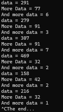
print('data = ' + data)
sleep(ms / 1500)
f.seek(1)
volt = f.read()[:-1]
print('More Data = ' + volt)
sleep(ms / 1500)
f.seek(2)
mill = f.read()[:-1]
print('And more data = ' + mill)
sleep(ms / 1500)
except KeyboardInterrupt:
pass
print("The end...")
# // BBB | Pocket | AIN
# // ----- | ------ | ---
# // P9_39 | P1_19 | 0
# // P9_40 | P1_21 | 1
# // P9_37 | P1_23 | 2
# // P9_38 | P1_25 | 3
# // P9_33 | P1_27 | 4
# // P9_36 | P2_35 | 5
# // P9_35 | P1_02 | 6
Not all but some of that source can be found here: https://docs.beagleboard.org/books/beaglebone-cookbook/02sensors/sensors.html#sensors-ultrasonic-fig
There is a small write up on the subject. For now, as this is an ongoing project, I will adding content and extra data as time permits...
Also:
I found some data to the subject of voltage to mm conversion via an AI bot online...
The conversion source is listed below...
def volts_to_mm(voltage, conversion_factor):

    """

    Converts a voltage value to millimeters using a given conversion factor.


    Args:

        voltage (float): Voltage value in volts.

        conversion_factor (float): Number of millimeters per volt.


    Returns:

        float: Distance in millimeters.

    """


    distance_mm = voltage * conversion_factor

    return distance_mm


# Example usage:

sensor_voltage = 2.5

mm_per_volt = 0.01  # Assuming 1 volt equals 10 millimeters

distance = volts_to_mm(sensor_voltage, mm_per_volt)

print(f"Distance in mm: {distance}")
So, an example of creating the voltage data to millimeter via mathematics and knowledge leads to this equation:
(resolution of the adc / system voltage) which is really (the adc reading / analog voltage measured)
Okay. Since the voltage of the ADC is maxed out at 1.8v roughly without harm done to the peripheral or am335x, we can then proceed with our equation:
The data below was scraped together from ti.com. The link is located here: https://software-dl.ti.com/processor-sdk-linux/esd/docs/latest/linux/Foundational_Components/Kernel/Kernel_Drivers/ADC.html
D = Vin * (2^n - 1) / Vref
where:
D = Digital value
Vin = Input voltage
n = No of bits
Vref = reference voltage
Ex: Read value on channel P9_39 for input voltage supplied 1.01:
Formula:
D = 1.01 * (2^12 - 1) / 1.8
D = 2297.75
When testing the analog voltage of a steady 1.8v or less than that voltage, there are some things to take into consideration for the ADC and source code? Do not go in excess of 1.8v.
Seth
P.S. Here is my data. It was acquired via the BBB and ADC onboard:
I have been testing other source for inches and millimeters but my logic is off. If you see the incorrect logic, please jump on in:
#!/usr/bin/python3

# //////////////////////////////////////
# // ultrasonicRange.py
# // Reads the analog value of the sensor.
# //////////////////////////////////////

from time import sleep
import math

foot = 12
inch = foot / 12
mm   = inch * 25.4

ms = 550.0  # Time in milliseconds

pin = "0"        # sensor, A0, P9_39

IIOPATH='/sys/bus/iio/devices/iio:device0/in_voltage'+pin+'_raw'

f = open(IIOPATH, "r")

ADC = (3.3 / 512) / inch
ADC_mm = (1.8 / 512) / mm

try:
    print("We are waiting one second and then starting")
    sleep(1)
    ADC = str(input("Please type anything,...
Read more »

 ivoras
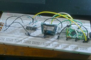
 Clovis Fritzen
Testing will ensue!