yaluke
-
Chapter 3 - JTAG
03/25/2025 at 19:38 • 0 commentsAs I found in chapter 1, my TP-Link TL-WR1043ND ver 1.8 router has a JTAG port available on the board. This discovery opens up exciting possibilities for deeper exploration and manipulation of the device. JTAG (Joint Test Action Group) is a powerful interface that allows direct access to the router's hardware, enabling advanced debugging, firmware extraction, and even potential security research.
In this chapter, we'll delve into connecting to the JTAG port using a Raspberry Pi 5 as our debugging tool. This approach offers a cost-effective and accessible method for hardware enthusiasts and security researchers to interact with the router at a low level. We'll explore the capabilities of JTAG, from basic connectivity to more advanced operations like dumping the router's flash memory.
Let's embark on this journey to unlock the full potential of our TP-Link router through the power of JTAG interfacing.
What is JTAG?
JTAG, which stands for Joint Test Action Group, is a powerful and versatile hardware interface standard that has become integral to electronics testing, debugging, and programming. Originally developed in the 1980s, JTAG was designed to address the challenges of testing increasingly complex printed circuit boards (PCBs) with densely packed components.
At its core, JTAG provides a standardized method for accessing and controlling the pins of integrated circuits (ICs) on a PCB without the need for physical probing. This is achieved through a simple serial interface, typically consisting of four or five pins:
- TCK (Test Clock)
- TMS (Test Mode Select)
- TDI (Test Data In)
- TDO (Test Data Out)
- TRST (Test Reset, optional)
JTAG's primary functions include:
- Boundary Scan Testing: Allows for testing interconnections between ICs on a PCB without direct physical access.
- Debugging: Provides access to internal chip resources, enabling developers to inspect and modify registers, memory, and system state.
- Programming: Facilitates in-system programming of devices like FPGAs and flash memory.
The JTAG interface has become so ubiquitous that it's now found in most modern microprocessors, FPGAs, and many other types of ICs. Its versatility has made it an essential tool for hardware developers, allowing them to test, debug, and program devices throughout the development lifecycle and even after product deployment.
Raspberry Pi 5 as a JTAG debugging tool
The Raspberry Pi 5, released in late 2023, introduces a powerful yet cost-effective platform for JTAG debugging, particularly suited for enthusiasts and researchers working on projects like our TP-Link TL-WR1043ND router exploration. Priced at around $80 USD, it offers an accessible entry point into advanced hardware debugging.
Key features of the Raspberry Pi 5 as a JTAG debugging tool include:
- Improved processing power with the BCM2712 chip
- Enhanced GPIO capabilities
- Compatibility with standard JTAG protocols
However, the platform does come with some limitations:
- Limited official documentation for the new RPi I/O chipset (RP1)
- Lack of RTCK (Return Test Clock) support, affecting adaptive JTAG clocking
Despite these challenges, the Raspberry Pi 5 excels in firmware extraction tasks, achieving speeds of approximately 850 KB/s. However, it may show some limitations in real-time register access compared to dedicated professional debuggers.
The platform's versatility and low cost make it an attractive option for hobbyists and researchers, especially those working on projects like our router exploration. While it requires some additional configuration and workarounds, the Raspberry Pi 5 offers a powerful and flexible solution for JTAG debugging tasks.
Physical Connection: Raspberry Pi 5 to TP-Link JTAG Interface
JTAG Connector Identification
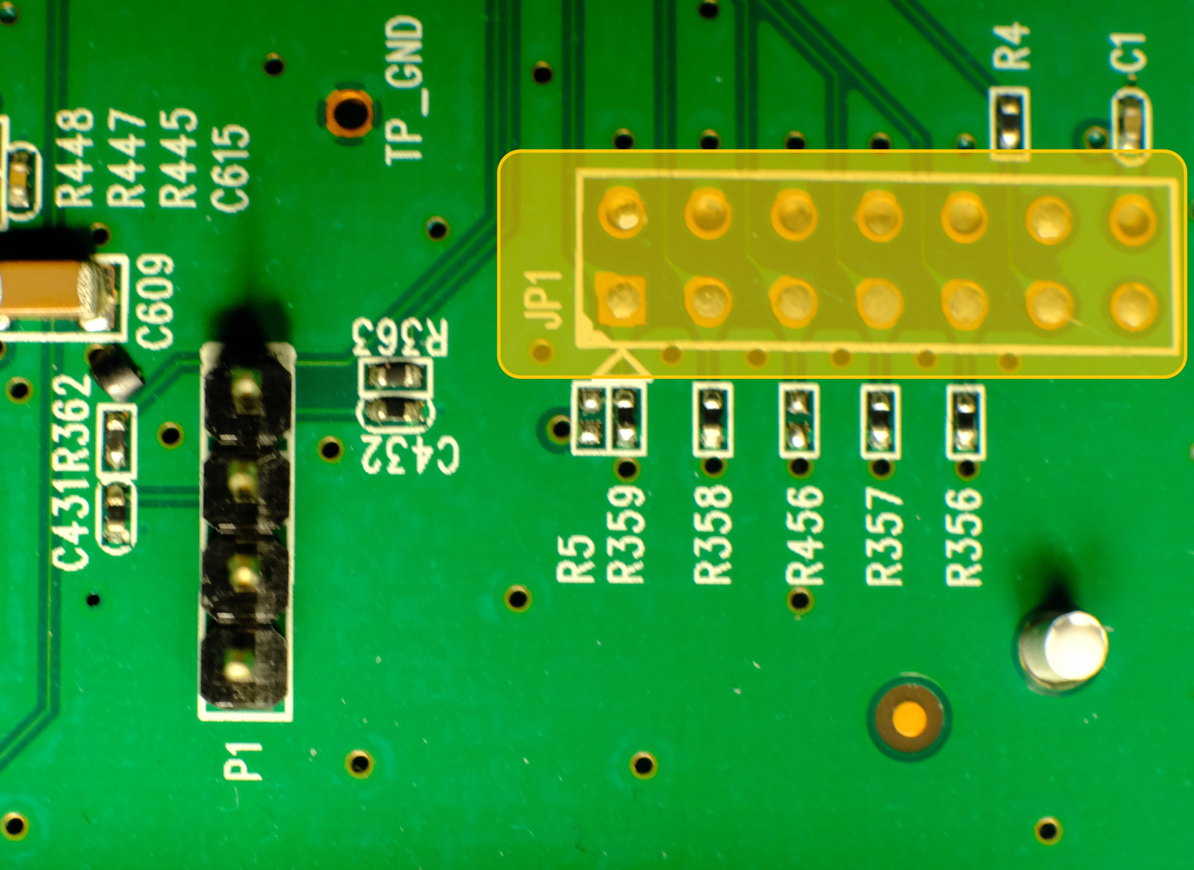
The TP-Link TL-WR1043ND v1.8 features a 14-pin EJTAG 2.6 standard header located near the serial port (labeled “JP1" on PCB):
![]()
This aligns with OpenWRT documentation confirming MIPS EJTAG compliance. The JTAG 2.6 header follows this pin arrangement:
Pin Signal Function 1 nTRST Test Reset (Optional) 3 TDI Test Data In 5 TDO Test Data Out 7 TMS Test Mode Select 9 TCK Test Clock 11 nSRST System Reset (optional) 2, 4, 6, 8, 10 GND Ground 14 VREF Voltage Reference (3.3V) 12, 13 Not used Minimal Raspberry Pi 5 Connection Scheme
Router JTAG Pin RPi 5 GPIO Physical Pin Signal Voltage 3 (TDI) GPIO26 Pin 37 3.3V 5 (TDO) GPIO24 Pin 18 3.3V 7 (TMS) GPIO27 Pin 13 3.3V 9 (TCK) GPIO25 Pin 22 3.3V 2 (GND) GND Pin 39 - Connection notes:
- Voltage compatibility: both devices use 3.3V logic - no level shifter required.
- It’s worth to solder goldpin header for stable connection.
- Maximum cable length: 15cm.
- ESD protection: work on grounded surface, use anti-static wrist strap.
- Connection sequence: router power off -> connect GND first -> connect signals -> power on router.
- Floating pins: unused JTAG pins should be left disconnected.
- Common pitfall: swapping TDO/TDI pins.
Raspberry Pi 5 software configuration
With physical connections established, we configure Raspberry Pi OS (Bookworm) for JTAG operation. On a fresh, updated system:
Enable JTAG in boot configuration:sudo nano /boot/firmware/config.txtAdd following lines under [all] section:
enable_jtag_gpio=1
gpio=22-27=a4
And reboot RPi.
To connect to the router OpenOCD (Open On-Chip Debugger) will be used. OpenOCD is a tool for debugging, in-system programming, and boundary-scan testing for embedded devices. Install dependencies first, then clone and build the tool
sudo apt install git libtool pkg-config autoconf automake texinfo libusb-1.0-0-dev libgpiod-dev build-essential
git clone https://github.com/raspberrypi/openocd.git
cd openocd
./bootstrap
./configure --enable-linuxgpiod
make -j$(nproc)
sudo make install
After successful installing OpenOCD create configuration file for this tool - name it rpi5-jtag.cfg and add following content:
adapter driver linuxgpiod

adapter gpio tck 25 -chip 4
adapter gpio tms 27 -chip 4
adapter gpio tdi 26 -chip 4
adapter gpio tdo 24 -chip 4
adapter gpio trst 22 -chip 4

transport select jtag

source [find target/atheros_ar9331.cfg]
Last, optional line add hardware specific configuration to this file - as there is no config for Atheros AR9132, similar (working) chipset is used. To verify if it works type:
sudo openocd -f rpi5-jtag.cfgAnd check if there are no warnings or errors in the output:
Open On-Chip Debugger 0.12.0+dev-gcf9c0b41c (2025-03-24-21:05)
Licensed under GNU GPL v2
For bug reports, read
    http://openocd.org/doc/doxygen/bugs.html
ar9331_ddr2_init
Info : Listening on port 6666 for tcl connections
Info : Listening on port 4444 for telnet connections
Info : Linux GPIOD JTAG/SWD bitbang driver
Info : Note: The adapter "linuxgpiod" doesn't support configurable speed
Info : JTAG tap: ar9331.cpu tap/device found: 0x00000001 (mfg: 0x000 (<invalid>), part: 0x0000, ver: 0x0)
Info : [ar9331.cpu] Examination succeed
Info : starting gdb server for ar9331.cpu on 3333
Info : Listening on port 3333 for gdb connections
Now OpenOCD runs and waits for connection.
Dumping flash using JTAG
As OpenOCD reported, it listening on port 4444 for telnet connection. Let’s switch to another terminal; after installing telnet and connecting to our device using following commands:
sudo apt install telnet

telnet localhost 4444
We should see:
Trying ::1...
Connection failed: Connection refused
Trying 127.0.0.1...
Connected to localhost.
Escape character is '^]'.
Open On-Chip Debugger
>
We are in! Now we can play with the router - check available commands with help (there are a lot more possibilities than using UART). To dump flash content (without custom script with error handling as we did in the chapter 1) type:
> halt
> dump_image full_flash.bin 0xbf000000 0x800000
And after around 40 minutes binary file is on the disk.
This configuration leverages the RP1's GPIO interface despite its performance limitations, providing a functional open-source alternative to commercial JTAG debuggers. The GPIO mapping reflects physical constraints of the Pi 5's revised layout compared to earlier models.
-
Chapter 2 – Firmware Tour
03/17/2025 at 14:58 • 0 commentsThe binary file dumped earlier from the flash memory is not merely a collection of random data. In this chapter, I'll demonstrate how to analyze and extract useful information from such a binary file for further analysis and potential modifications. I'll be using Kali Linux for this process, but other Linux distributions should work similarly.
Useful links
https://openwrt.org/toh/tp-link/tl-wr1043nd
https://openwrt.org/docs/techref/flash.layout
Initially, I planned to use the flash layout information provided by OpenWrt. However, I quickly realized that my router uses the original TP-Link firmware (version TL-WR1043ND_V1_140319), which differs from OpenWrt's layout. Therefore, there are no shortcuts—I must analyze the flash data manually.
First Raw View
Based on general information from OpenWrt documentation, I expected the following basic layout:
- Bootloader at the beginning
- Firmware header and kernel data following the bootloader
- SquashFS filesystem containing Linux files
- SoC-specific data stored at the end of the flash memory
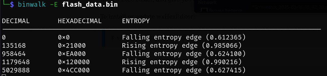
To verify this structure, I used `binwalk`, a tool that analyzes binary files to identify embedded filesystems, compressed data, and known signatures. Running:
binwalk flash_data.binproduced the following output:
![]()
From this analysis, I identified several key areas:
- 0x00000000: Bootloader section
- 0x00020000 (128 kB): TP-Link firmware header
- 0x00020200 (512 bytes later): Compressed Linux kernel (size: 1023.5 kB)
- 0x120000 (1152 kB): SquashFS filesystem containing the Linux file structure
Notably, no explicit information about SoC-specific data appeared at this stage. Thus, further manual analysis was necessary.
Extracting Firmware Components
Bootloader Extraction
The bootloader occupies the first 128 kB of flash memory. To extract it into a separate file, I used the Linux `dd` command, which copies specific parts of a file based on given parameters:
dd bs=1024 count=256 if=flash_data.bin of=bootloader.binHere, `bs` specifies chunk size (1024 bytes = 1kB), and `count` specifies how many chunks to copy (128 chunks × 1024 bytes = 128kB).
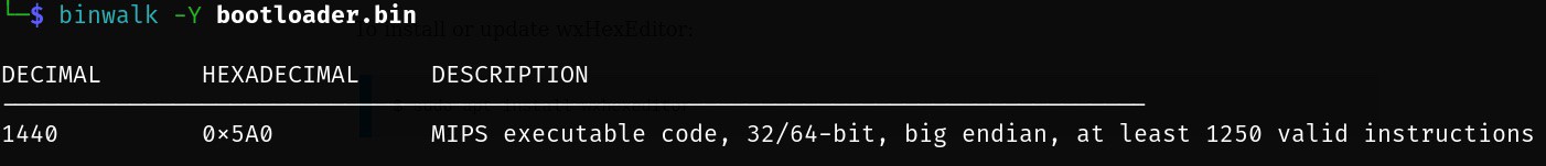
A bootloader is responsible for initializing hardware and loading an operating system. To confirm its architecture type, I ran:
binwalk -Y bootloader.binThis confirmed that router uses MIPS architecture:
![]()
TP-Link Header
Following the bootloader is a small TP-Link header occupying exactly 512 bytes. Extracting it is straightforward:
dd bs=512 count=1 skip=256 if=flash_data.bin of=tplink_header.binLinux Kernel
Next, I extracted the compressed Linux kernel using similar logic:
dd bs=512 count=2047 skip=257 if=flash_data.bin of=kernel.binSince this kernel is compressed, it can be manually decompressed using:
binwalk -Me kernel.binThis command produces _kernel.bin.extracted folder with uncompressed Linux kernel inside. As kernel is also valid executable file we can confirm architecture using binwalk -Y, similar to the bootloader case.
Linux Filesystem (SquashFS)
The SquashFS filesystem starts at offset `0x120000` (1152 kB) and occupies exactly `3852370` bytes. To extract it:
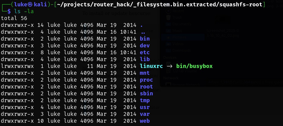
dd if=flash_data.bin bs=1 skip=1179648 count=3852370 of=filesystem.binThen, to unpack its contents using `binwalk`:
binwalk -Me filesystem.binThis command produces a directory containing the extracted Linux file structure:
![]()
Alternatively, another useful tool called `sasquatch` can also handle SquashFS extraction efficiently:
sasquatch -C lzma -be filesystem.binBoth methods successfully revealed the internal filesystem structure.
Identifying SoC-Specific Data
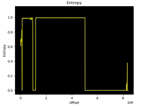
To locate SoC-specific data stored at the end of flash memory, I used entropy analysis (`binwalk -E`). Entropy measures randomness within data; low entropy typically indicates padding (`0x00` or `0xFF`) or uncompressed code sections, while high entropy suggests compressed or encrypted data. Running entropy analysis with standard parameters:
binwalk -E flash_data.binshowed clear entropy variations indicating different data types:
![]()
![]()
Further detailed inspection using a hex viewer revealed padding (`0xFF`) changing into structured data at offset `0x7E0000`. Upon closer inspection, router MAC addresses were clearly identifiable in this region. Further also users/passwords identified in the previous chapter can be identified. Based on OpenWrt data this part is ART = Atheros Radio Test which contains except of MAC addresses, also calibration data for the Wi-Fi.
Thus, extracting SoC-specific data was straightforward using:
dd if=flash_data.bin bs=1 skip=8064 of=soc_specific.binAlthough each component was individually extracted above for clarity and educational purposes, you can achieve similar results in one step using binwalk's recursive extraction feature:
binwalk -Me flash_data.binThis command automatically identifies and recursively extracts all embedded components from the dumped flash memory file.
Complete Flash Memory Layout Summary
Below is a complete summary of the identified flash memory layout for my TP-Link TL-WR1043ND router running original firmware version TL-WR1043ND_V1_140319:
Offset Size Content 0x00000000 128 kB Bootloader - responsible for hardware
initialization and OS loading0x00020000 512 B TP-Link Header - contains metadata
specific to TP-Link firmware0x00020200 1023.5 kB Compressed Linux Kernel image for
MIPS architecture0x00120000 ~3.7 MB SquashFS Filesystem - contains all
Linux system files.0x007E0000 128 kB SoC-specific Data - includes
device-specific details such as MAC
addresses, user credentials and
ART = Atheros Radio Test -
Chapter 1 – Recovering the Passwords
03/12/2025 at 06:29 • 0 commentsThe router had spent the last seven years forgotten in the back of a drawer. During that time, I used a device provided by my internet service provider. After connecting the old router to power, it booted successfully and started serving a network. However, I had no idea what the passwords were—neither for Wi-Fi nor for administration access. Before resorting to pressing the reset button, I decided to experiment and see if I could somehow retrieve the passwords.
Disassembling the Router
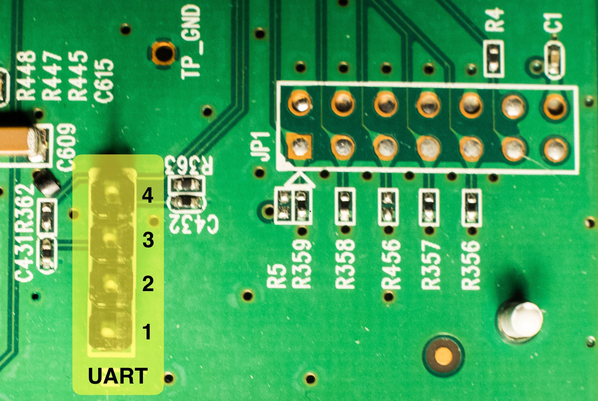
Disassembly was straightforward, though reading instructions beforehand would have been beneficial—I ended up breaking two fasteners in the process. A quick inspection of the PCB revealed two connectors: one 1x4-pin and one 2x7-pin connector. Documentation found on openwrt.org confirmed these connectors as UART and JTAG interfaces:
![]()
Connecting via UART Using Raspberry Pi 5
Since I didn't have a USB-to-serial adapter available, I decided to use a Raspberry Pi 5 (RPi) to communicate with the router through UART. The configuration was simple:
- First, I enabled the serial hardware interface on the Raspberry Pi using `raspi-config`.
- Next, with both devices powered off, I connected them as follows:
Raspberry Pi 5 Router UART GND (pin 6) pin 2 GPIO14/UART0 TX (pin 8) pin 3 GPIO15/UART0 RX (pin 10) pin 4 After making these connections, I powered on only the Raspberry Pi.
Using minicom to Access Router's Serial Console
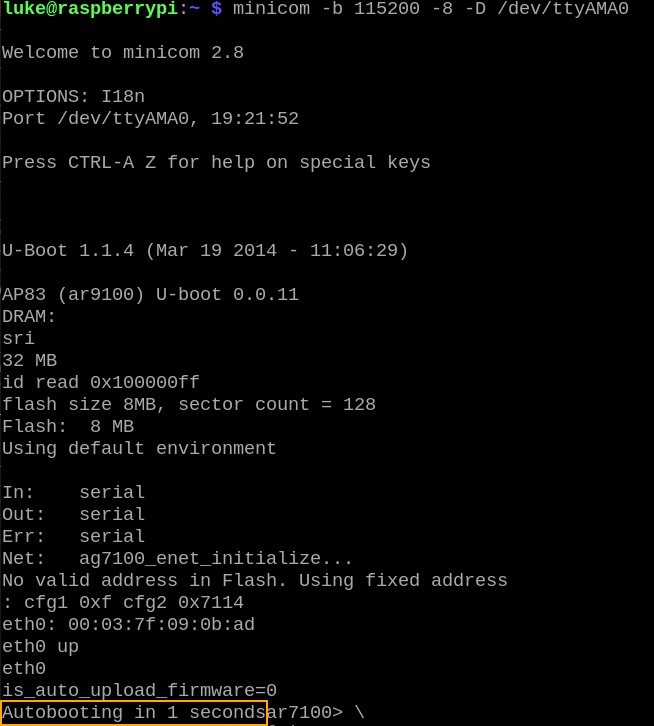
The first tool I used for communication was `minicom`, installed on Raspberry Pi with:
sudo apt install minicomUsing communication parameters provided by OpenWrt documentation—baud rate: 115200, data bits: 8, parity: none, stop bits: 1, flow control: none—and the RPi UART device (`/dev/ttyAMA0`), the command line looked like this:
minicom -b 115200 -8 -D /dev/ttyAMA0Minicom then waited for data from the router. Upon powering up the router, after a few seconds I saw this output:
![]()
When seeing "Autobooting in 1 second," I quickly typed `tpl` followed by <enter> to interrupt booting and enter the boot prompt. At this prompt, various commands were available (`help` lists them all). However, only one command seemed useful for inspecting memory contents: `md` (memory display).
Dumping Router Flash Memory
I assumed passwords were stored somewhere within flash memory, which should be mapped into address space. Based on OpenWrt documentation (flash layout and flashing instructions), I confirmed that flash memory starts at address `0xbf000000` and occupies an 8 MB address range. This was precisely the area I wanted to dump and analyze.
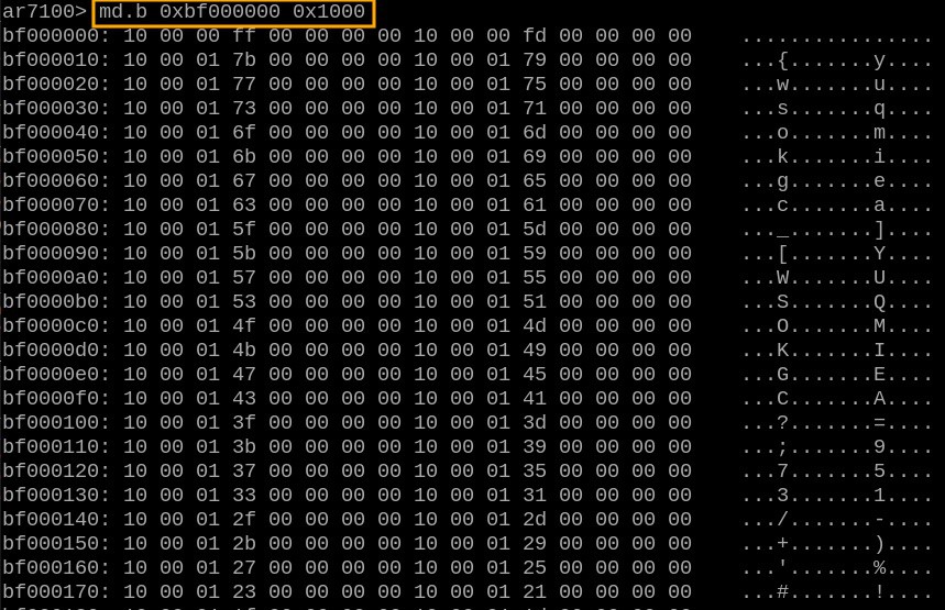
Minicom offers an option (`-C`) to log all communication into a file. Initially, my idea was to use this feature along with the `md.b` command to dump flash memory:
![]()
Output from `md` can be parsed easily and converted into binary format for an exact copy of flash data. Unfortunately, random chunks of data occasionally went missing during dumping—I wasn't sure if this was due to issues with the router itself, Raspberry Pi hardware limitations, or something else entirely.
Reliable Data Dumping with Python Script
To ensure reliable data dumping—checking for missing data and retrying failed reads—I decided to write a Python script using the `pyserial` library (`pip3 install pyserial`). Here's a snippet of Python code that automates connecting to the router's boot prompt (eliminating manual typing of `tpl`):
import serial
from time import sleep

with serial.Serial('/dev/ttyAMA0', 115200, timeout=1) as conn:
        # connect and "login"
        logged_in = False
        buffer = ''
        while(not logged_in):
            x = str(conn.read(), encoding='utf-8')
            buffer = buffer + x
            print(x, end='')
            if len(buffer) >= 24 and buffer[-24:] == 'Autobooting in 1 seconds':
                # now we have 1 second to "login"...
                sleep(0.1)
                # by sending 'tpl' string to device
                conn.write(bytes('tpl\n', 'utf-8'))
                # let's read all the stuff before sending next command
                x = str(conn.read(100), encoding='utf-8')
                print(x)
                logged_in = True
The rest of my Python script is straightforward—it reads memory data in small chunks, verifies integrity, retries failed reads if necessary, and saves valid data into three separate files:
- Text output from `md`
- Binary data dump
- Error logs (for reference)
The complete script is available here: https://github.com/yaluke/router_hack/blob/main/read_flash.py
Finding Passwords in Dumped Data
With all flash data collected successfully, it was time to search for passwords.
Wi-Fi Password Recovery
I started with recovering the Wi-Fi password since it seemed easier—especially because I already knew my network's SSID (network name). A quick search showed that my network name appeared exactly once in the dumped file. Just a few lines below it was something resembling a password:
![]() Testing confirmed success—I could connect to my router's Wi-Fi network!
Testing confirmed success—I could connect to my router's Wi-Fi network!Admin Password Recovery
Recovering the administrator password proved trickier since I didn't know the username either. To identify potential usernames and passwords stored in binary form, I used Linux's built-in `strings` utility:
strings firmware.bin > strings_output.txtBy default (`strings` with minimum length set at four characters), this yielded around 56k results—far too many lines to check manually. Assuming usernames/passwords would typically be longer than four characters, I adjusted string length filtering using `-n`. Setting minimum length at eight characters reduced results significantly—to about 1.5k strings—which was manageable for manual inspection:
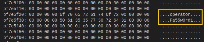
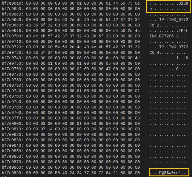
strings -n8 firmware.bin > strings_output.txtGiven typical flash layouts where configuration data (including passwords) is usually stored toward memory's end region, I began checking strings from there first—and quickly found administrator credentials here (md output):
![]()
A quick test confirmed success—I regained administrative access!Conclusion
Mission accomplished! By inspecting router memory directly via UART connection and careful analysis of dumped flash memory contents, I successfully recovered both Wi-Fi and administrative passwords without resetting my device.
This experiment also revealed that these sensitive credentials were stored without any encryption or protection measures—a concerning practice. It makes me wonder if such insecure storage methods are common industry-wide...
Wi-Fi Router Autopsy
Breathe new life into an old Wi-Fi router: explore hardware - software connections, reverse engineer components, and test security.

 Testing confirmed success—I could connect to my router's Wi-Fi network!