 Dan Julio
The design, firmware source and pre-compiled binaries, and build instructions may be found on github. It is released under the GPL v3 license. Links to the various parts I used can be found there.
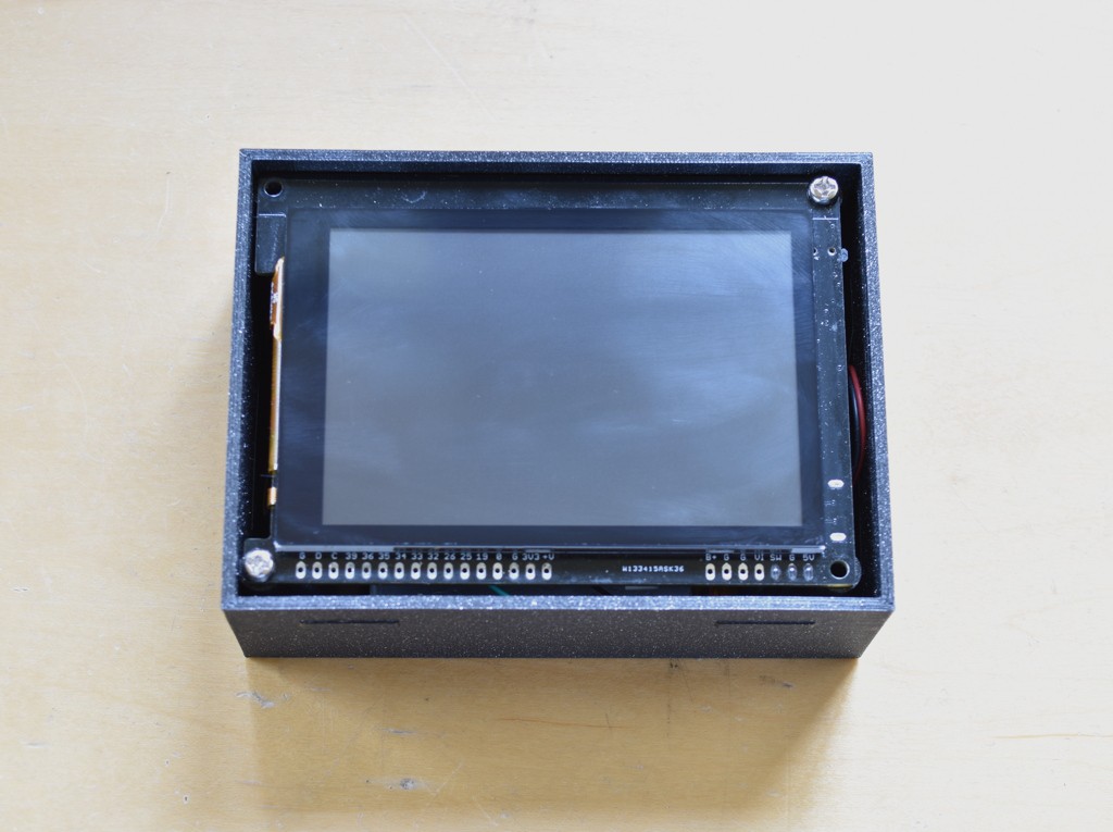
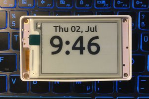
Physically the clock is built around a teak 2x3" picture frame I found on Amazon.
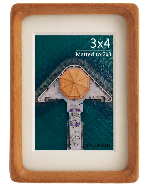
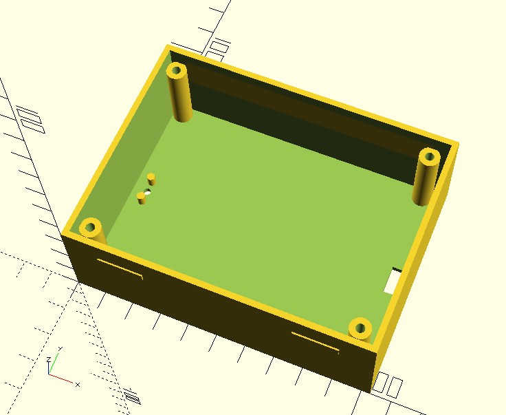
This perfectly fits the gCore's 480x320 pixel LCD and PCB. The original photo backing is replaced by a 3D printed enclosure that holds the electronics. The enclosure was designed using OpenSCAD.
I suppose that over time the picture frame will become unavailable but the design should be easily modified for another frame.
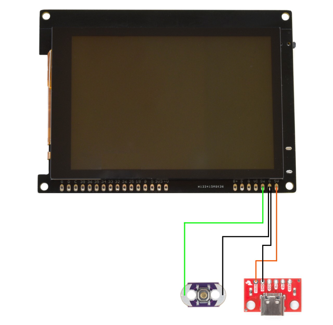
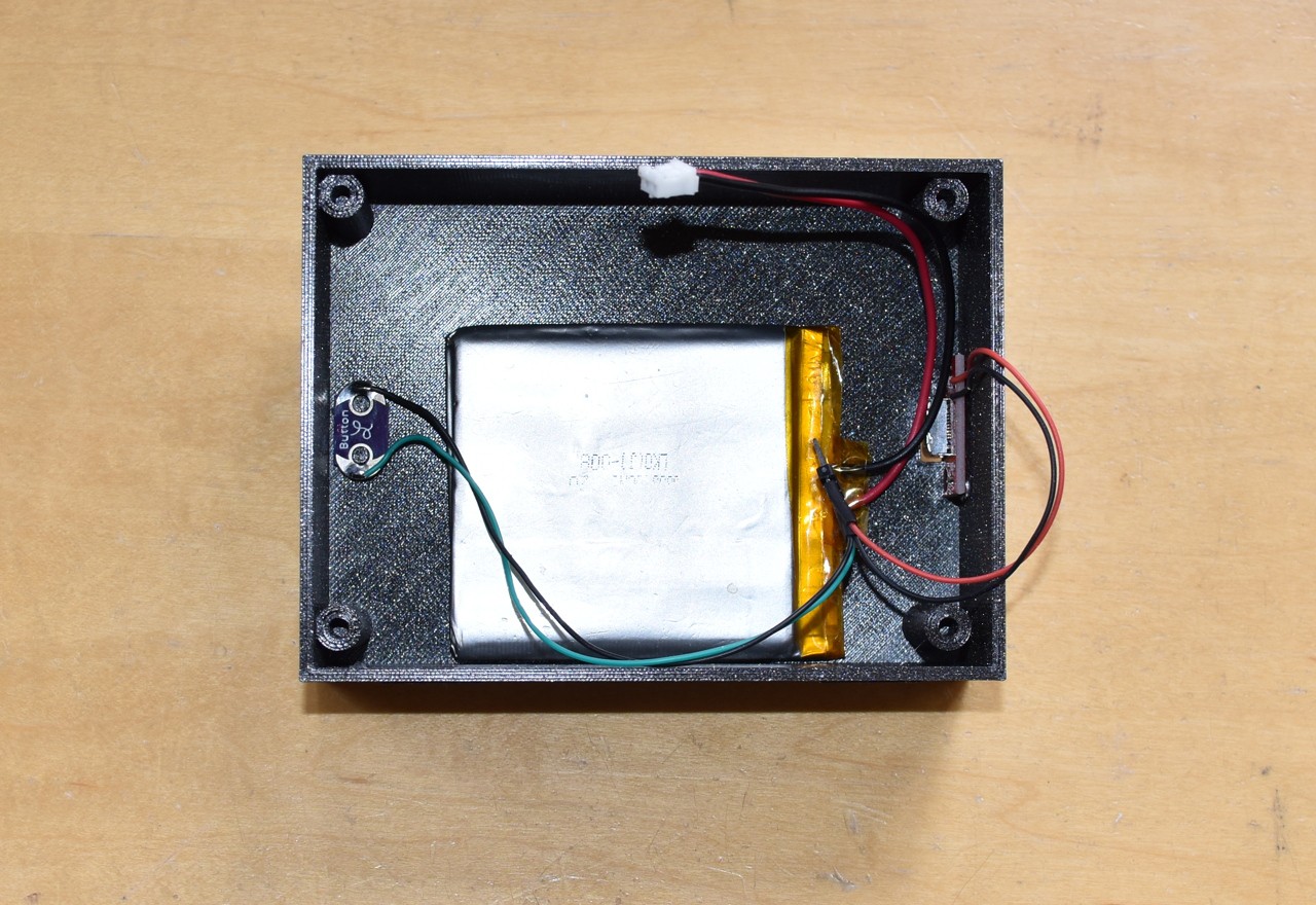
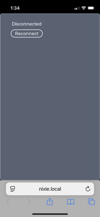
A USB C breakout board and Lilypad button are wired to gCore to provide external access for power and on/off/wi-fi reset control. A small LiPo battery can keep the clock running for hours during a power fail before turning off when the battery reaches 3.5V (the RTC continues to run). Typically the clock takes 100 mA or less.


 Martin Fasani
 Francesco Comi
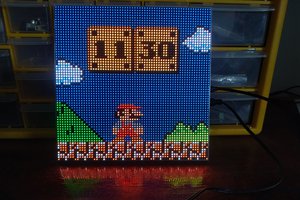
 Jonathas Barbosa
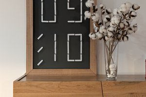
👍 Faux nixies look great. For one thing you can have colours other than orange. I kinda like "blue nixies".