An attempt to build a reproduction of this iconic hand-held game system.
To make the experience fit your profile, pick a username and tell us what interests you.
We found and based on your interests.
So the assembly is almost finished, and then I suddenly noticed something strange when I placed it next to the original:
The width is wrong. Somehow there is something missing on the right side, and there is more space surrounding the joypad than in my design. Which I have not noticed until now. How could this happen?
Well, it turns out the Lynx is just not symmetrical, something I assumed all the time while designing my replica housing. Which you can see here:
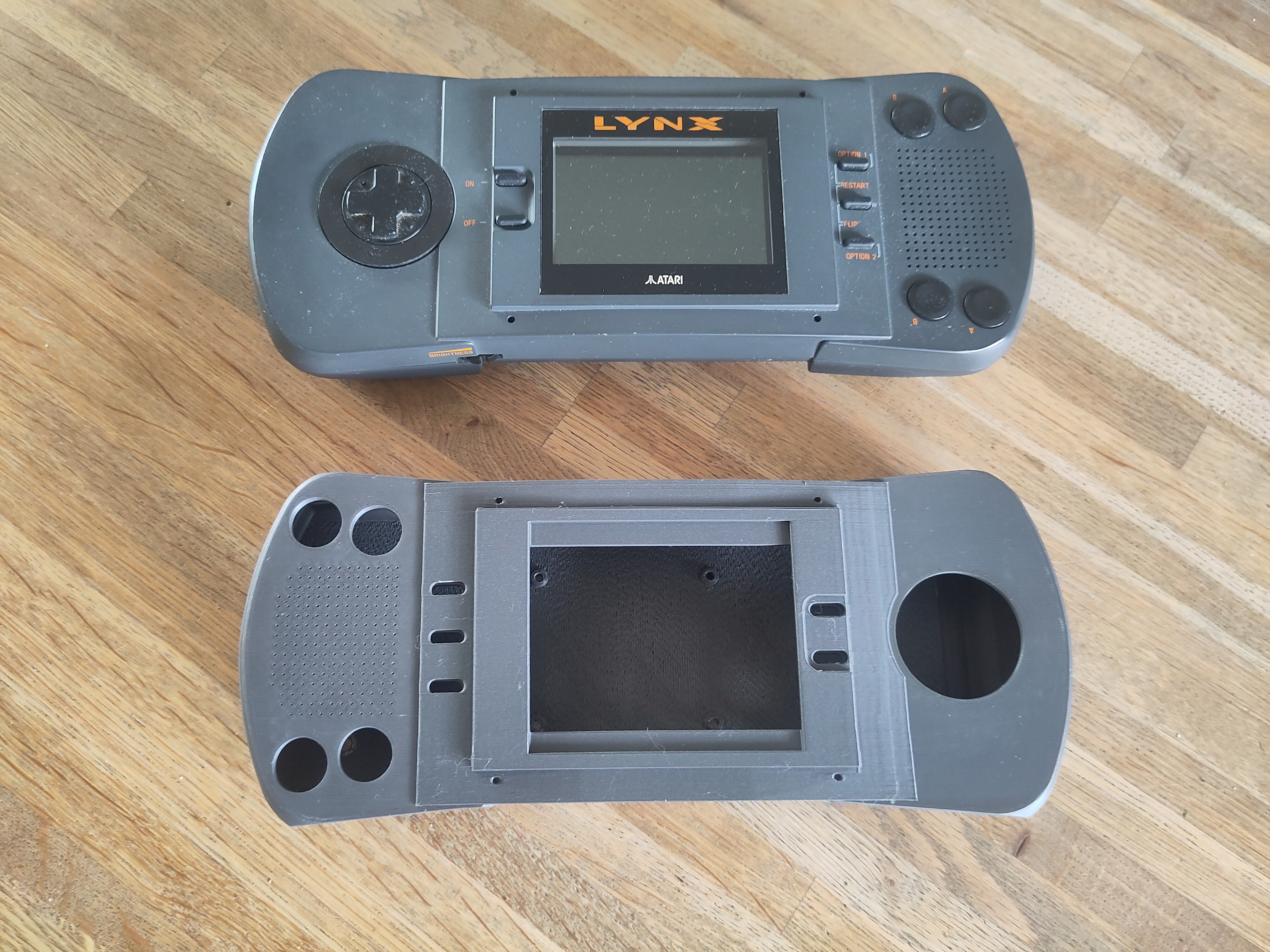
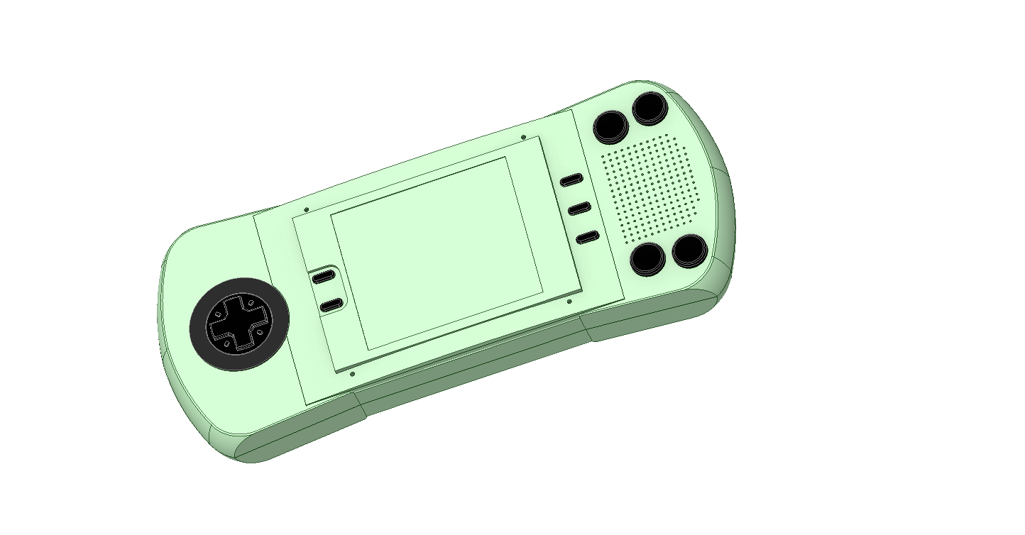
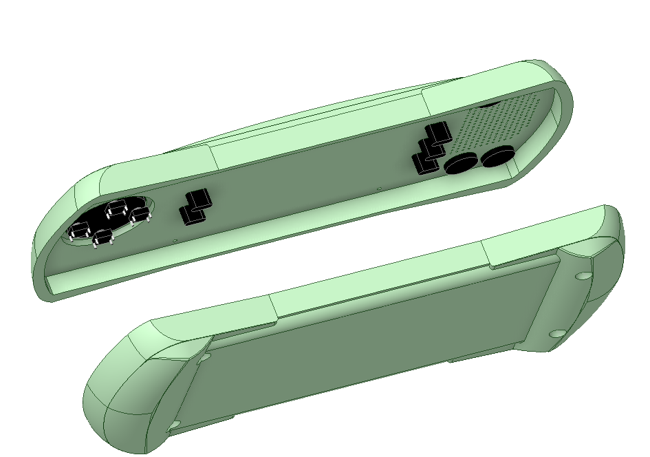
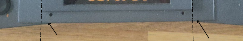
The screen is in the middle, but the side-sections start at a different distance from the edge of the screen. And once this is corrected, the front indeed looks even more like the original:
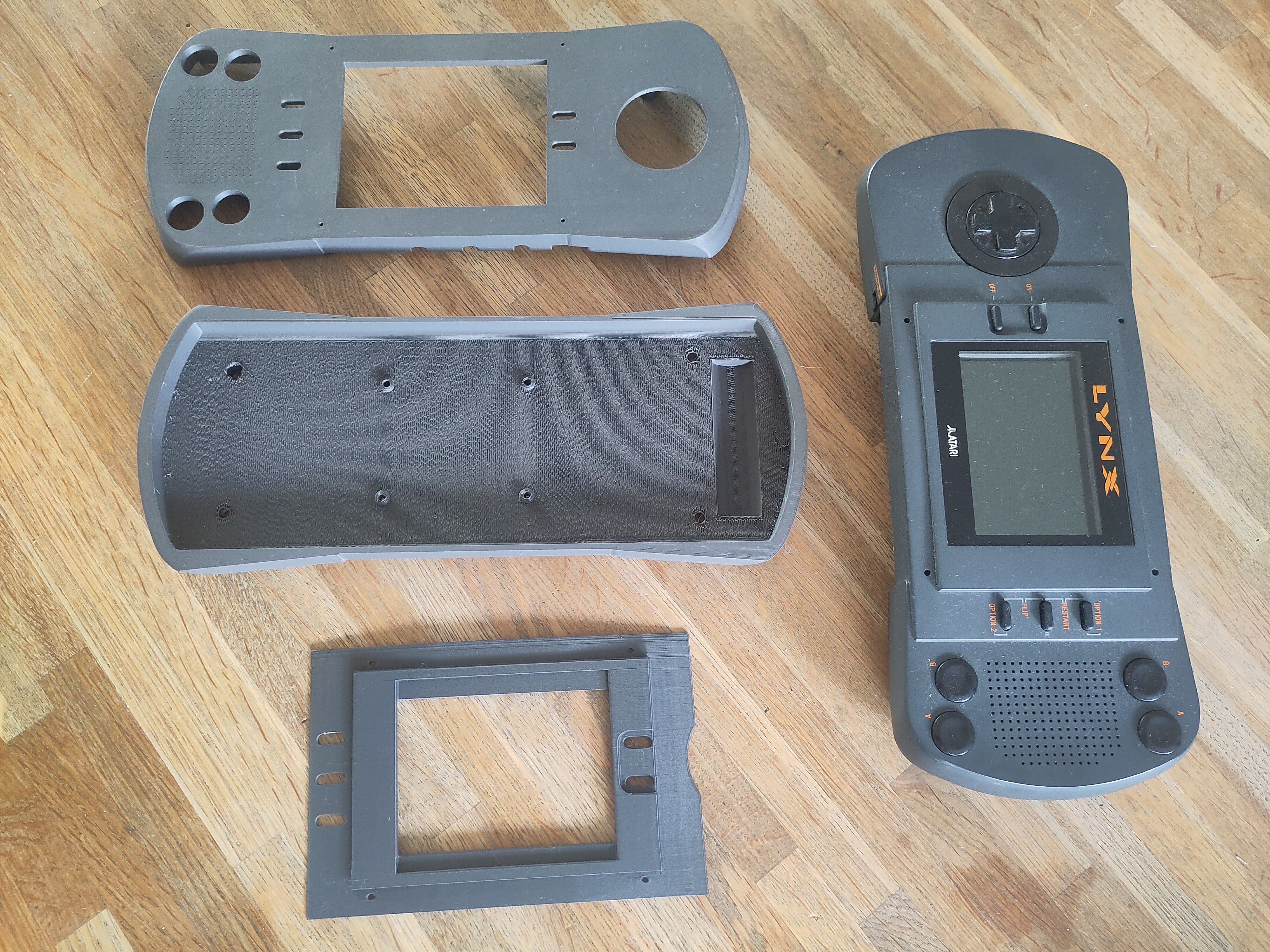
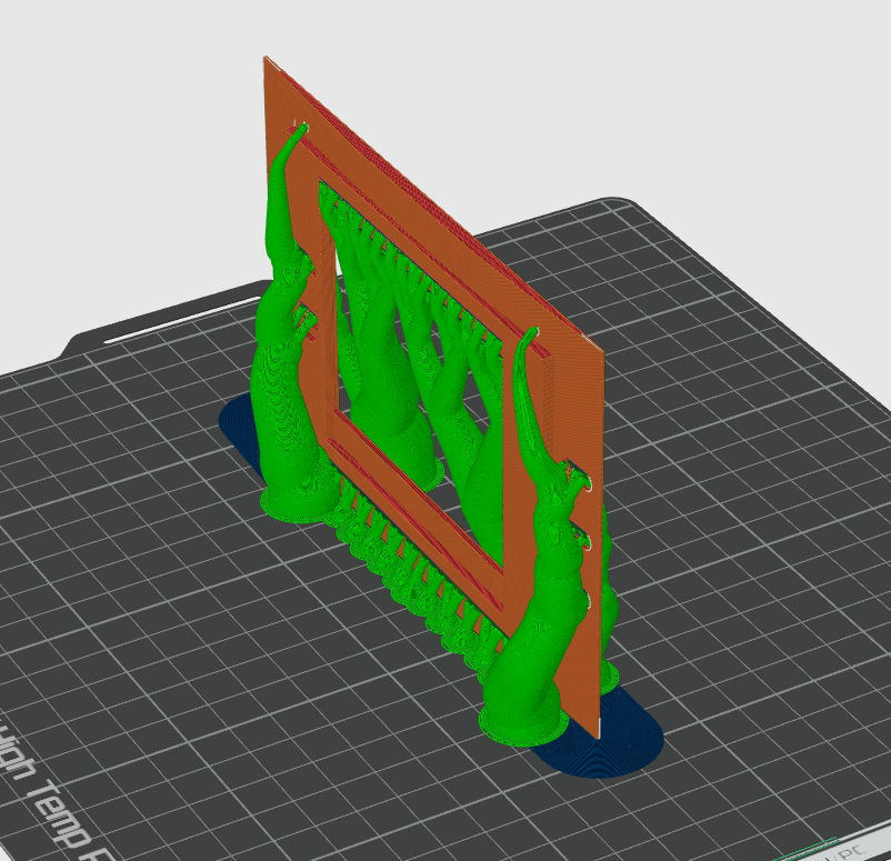
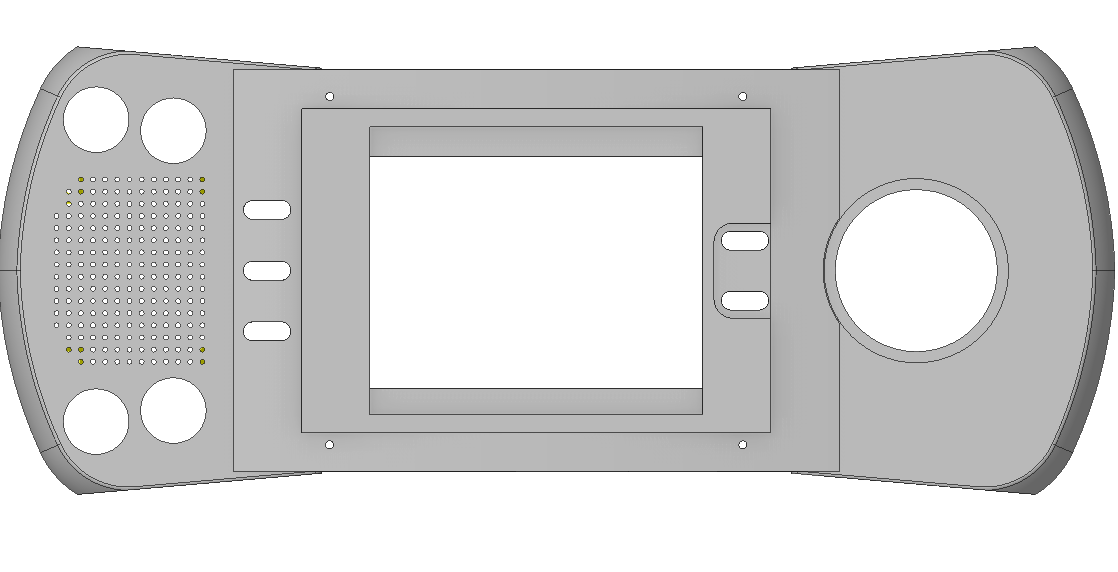
Apart from this there were several small changes that I made to to front, like increasing the hole size for the buttons, so I decided to print it again:
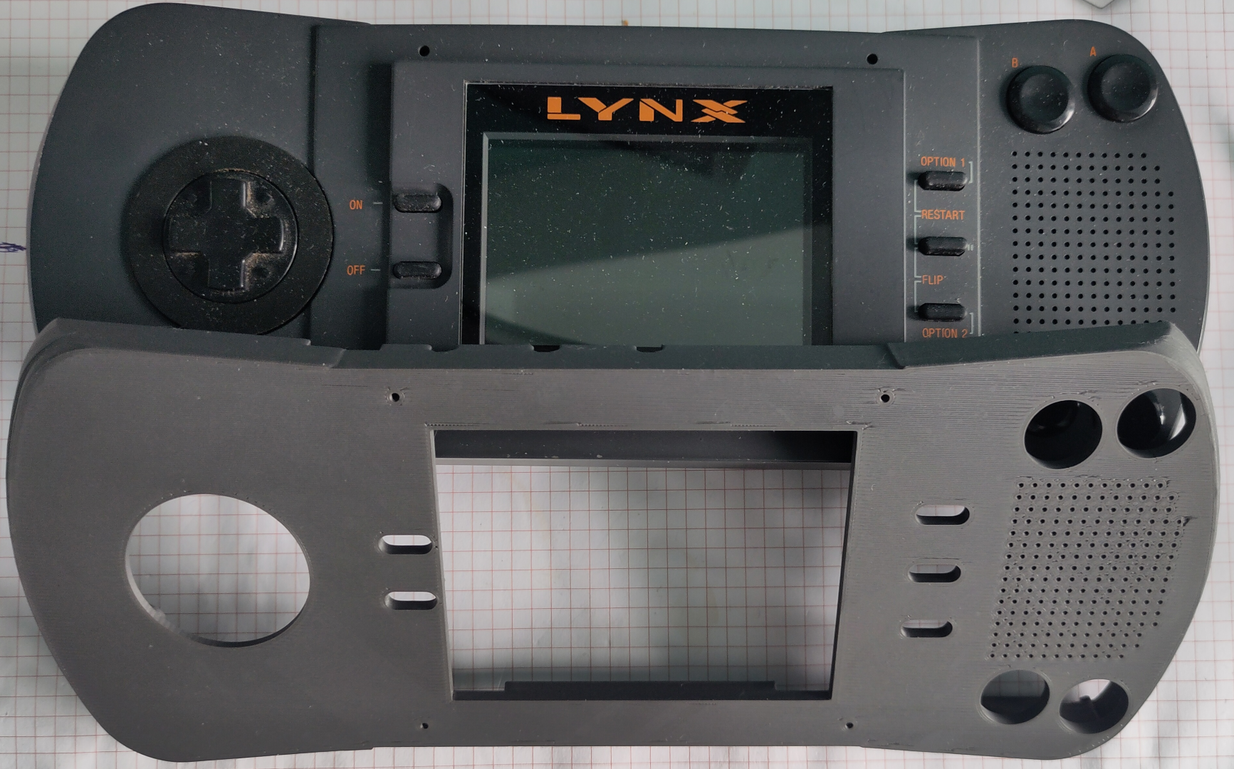
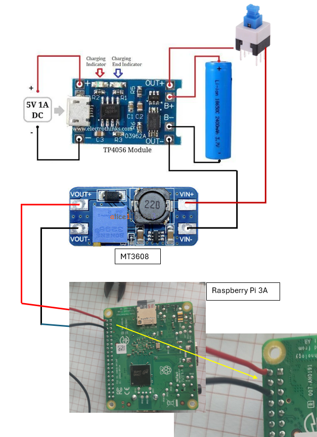
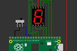
Soldering the wires directly to the switches, so close to the PLA frame is a challenge. The plastic tends to melt rapidly when a soldering iron approaches. But its possible and little melting it not too bad. For the wiring itself I followed this schematic:
Well, more or less. It actually does not matter that much which switch is where, since each switch is assigned a specific function at the first start of the RetroPie software. And there is no analog joystick as shown here connected to A2 and A3.
How the power is wired:
The Battery is connected to the TP4056 charger. From there the battery voltage (3.7V) is routed through the switch to the MT3608 voltage converter which is set to exactly 5 VDC output. This voltage is applied directly to pin 2 and 6 of the Raspberry Pi GPIO header.
And so we can test the final circuit. It works!
As always, drawing all the tiny little details takes way more time than expected. But I finally got to the point where I could start printing. And it turned out great! Using the 'Polymaker Panchroma™ PLA Matte filament Ash Grey' turned out to be a really good match for the original color.
The top section was printed in two parts. By printing the 'curved' section vertically it gave a real smooth finish.
Yes, it does require a lot a of support material...
Unfortunately I could not get the ESP32 with RetroGo to work with a display of the right size. It just has to be a 3.5 inch display, or my Lynx won't look real. So I return to the Raspberry Pi 3A+ like in my previous project, and a MPI3508 3.5" HDMI Display. And yes, this just works. Insert the RetroPie SD card, apply power, and it starts. Not as fast as I would like it, but maybe I can shave off a few seconds later if I just focus on only Lynx Emulation.
The Pi + screen combination also makes for a compact building block that will be easy to mount in the housing.
This also means I can just wire it exactly the same as I did for the RetroPie Handheld. Making this project slightly less fun, but way easier to finish.
The retro-go project does not have specific instructions on how to wire things for each 'target'. As I have chosen the ESP32S3-DEVKIT-C, the 'config.h' contains all necessary details.
C:\ESP32\retro-go\components\retro-go\targets\esp32s3-devkit-c\config.h
Here we find the GPIO numbering for both the LCD screen and the SD-Card:
// Status LED
#define RG_GPIO_LED GPIO_NUM_38
// SPI Display (back up working)
#define RG_GPIO_LCD_MISO GPIO_NUM_NC
#define RG_GPIO_LCD_MOSI GPIO_NUM_12
#define RG_GPIO_LCD_CLK GPIO_NUM_48
#define RG_GPIO_LCD_CS GPIO_NUM_NC
#define RG_GPIO_LCD_DC GPIO_NUM_47
#define RG_GPIO_LCD_BCKL GPIO_NUM_39
#define RG_GPIO_LCD_RST GPIO_NUM_3
#define RG_GPIO_SDSPI_MISO GPIO_NUM_9
#define RG_GPIO_SDSPI_MOSI GPIO_NUM_11
#define RG_GPIO_SDSPI_CLK GPIO_NUM_13
#define RG_GPIO_SDSPI_CS GPIO_NUM_10
// External I2S DAC
#define RG_GPIO_SND_I2S_BCK 41
#define RG_GPIO_SND_I2S_WS 42
#define RG_GPIO_SND_I2S_DATA 40
// #define RG_GPIO_SND_AMP_ENABLE 18
That's simple. Yet it does not work. When booting up, the screen flickers and stays white. Checked the wiring several times, until I suddenly noticed the bag in which the display came. It says 'ILI9488 Driver'. And the code refers to the 'ILI9341', which was also mentioned on the AliExpress page where I ordered the display. So that page is incorrect, and this display is actually based on the ILI9488. And yes, that requires a different setup, not least because it is 320x480 pixels instead of the 240x320 of the ILI9341.
There is an AdaFruit example library for both displays, so I copied the setup code from the IL9488 to the config.h file. Not knowing what any of these codes do, making it a long shot. And so that did not seem to work, as expected. But, just as I thought I should give up, I switched power off and on to the board, and then suddenly an image appeared on the screen. It is black and white, and the orientation and aspect is wrong, but it shows that the connections are OK, and the setup is at least partially right.
So now the question arises: will I try and fix the driver code to make it work with this specific display? It will require a deep dive into the details on memory, registers and pixel colors. Not sure If I really want to spend that much time on it.
As mentioned, I chose the ESP32-S3-DevKitC-1. Programming requires the ESP-IDF, for which the installation instructions can be found here.
Of course I rushed it, without reading the whole page and so I missed the note that it is best to install it from the VS Code extension. And when you installed it using the 'Windows Installer', adding it to VSCode simply fails. So I had to uninstall it, and then follow the VSCode way.
If all goes well ( and why shouldn't it..) you end up with the start screen for ESP-IDF:
Right. But what next ? First I tried some things like 'import project', or 'new project', but that does not get you anywhere.
First, make sure your 'retro-go' folder is somewhere in a 'root' folder, like C:\ESP32\retro-go. Then open the folder in VSCode. This will that ask if you want to open a workspace. Answer yes.
Next, open the ESP-IDF Terminal. Here we can now enter the commands as described in the 'BUILDING.md' file.
I used this command:
During the first build I ran into a few issues in the code, but these were easy to fix:
In 'rg-storage.c' : rom/miniz.h not found. Right, because that is in a different folder:
#ifdef ESP_PLATFORM
#include <libs/miniz/miniz.h>
in 'memmap.c' : incorrect modifier in print statement. Argument 5 is a long int. So you should change the '%dkB' to '%ldkB'
printf("Rom loaded: name: %s, id: %s, company: %s, size: %ldKB\n", Memory.ROMName, Memory.ROMId, Memory.CompanyId, Memory.CalculatedSize / 1024);
In 'opl.c' :
static int *mix_buffer = NULL;
Must be:
static long int *mix_buffer = NULL;
But that was all. And after a long compilation/ build, it finally started the upload to the connected board.
And it looks like the program is running, since the 'Tx' LED on the board is now blinking at a regular pace. To see what is going on, start the monitor:
After the startup messages of the ESP32 (which will show some errors, since I have not connected anything yet) it will start to print [DEBUG] messages. So it looks like it is working.
Since I already built a handheld in the past (https://hackaday.io/project/176661-retropie-handheld) that did Atari Lynx emulation, the Raspberry Pi is a logical choice. A drawback of using the Pi though is that it takes quite some time to boot into the emulator, which does not make you feel yo are using a 'real' Lynx. But while designing the housing it struck me that it might be a great fit for the 'CYD' or 'Cheap Yellow Display'. Unfortunately when placing this unit in the design it is obviously a little too small. Which is correct: this is a 2.8" screen, and the Atari has a 3.5 ". Using an ESP32 based solution would however ( probably) solve the boot problem, and most likely use less power.
There is an ESP32 based emulator: https://github.com/ducalex/retro-go. It seems that it is only readily available for the Odroid-Go and MRGC-G32, but it should be possible to run it on other devices as well. It supports screens that have a ILI9341 driver, which are available in different sizes at AliExpress. I ordered the 3.5"TFT version, which seems like a nice size for the Lynx.
And this ESP32-S3 board seems powerful enough to run this application:
It can be found in the Retro-Go Github as 'ESP32-S3-DevKitC', so there is some support available. Lets try to get it running...
There are a few 3D models of the LYNX available, but I decided to model it myself in DesignSpark Mechanical.
Create an account to leave a comment. Already have an account? Log In.
Yes, I was aware of the McWill mod. Considered a few times, but was held back by the price, and the fact that the replacement itself is rather tricky.
Hey Cees, Fellow countryman, this sounds like an interesting project. Are you reusing the original hardware?
Nope. This is going to be a reproduction. The interior will probably be a RaspberryPi or ESP32 module. Haven't decided yet. I'm definitely not going to take apart my original...
Sounds great! I’m on a similar venture, utilizing a Raspberry Pi to run old Atari 2600 cartridges. Looking forward to seeing how yours turns out!
Become a member to follow this project and never miss any updates
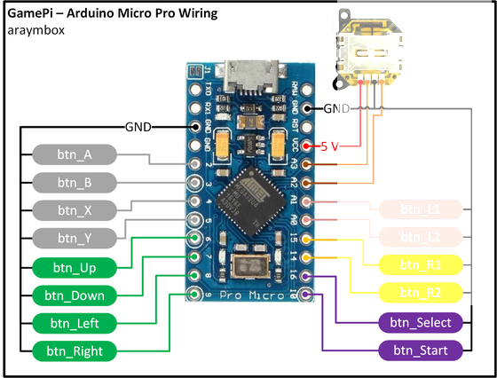
Jacob David C Cunningham
davedarko
Open Technology
Nice project, and I don't want to detract from the DIY approach! But if you want a nicer screen for your original Lynx there are modern backlit replacements available, e.g https://dragonbox.de/en/upgrade-kits-do-it-yourself/lynx-i-lcd-mod-mcwill-rev-3