 Zachary Murtishi
-
Bug fixes and code optimization
05/10/2025 at 01:14 • 0 commentsI decided to finally install 2032 cell holders for the boards and went to test them, only to realize that the timing of the EFM8's RTC was off. I dug into the code and ended up cleaning up / optimizing a lot of it while trying to figure out why the RTC was acting up, only to end up investigating the ISR for the RTC wakeup.
I noticed that upon the RTC alarm interrupt firing, the EFM8 would often "forget" to execute code after its ISR. This all began when I cleaned up the ISR to remove excess code (it's not great to have bloated ISRs) - turns out, some excess code in there was generating a delay that we seem to need. The EFM8 reference manual does suggest 4 NOP instructions following a wakeup, but it doesn't seem as the 4 instrinic NOPs I have in the code are working, so I threw in a uint8_t i; for(i=0; i<16; i++); to generate this delay.
The RTC now seems to work well now with that delay in place...wondering why the delay needs to be longer than the reference manual suggests.
-
Bug fix: interrupt priority
04/14/2025 at 22:49 • 0 commentsI noticed that the RTC alarms were failing to put the ornament into sleep mode whenever light patterns that depended on Timer0 interrupts were on. I figured that this may be due to the fact that the Timer0 held priority over the RTC alarm interrupt and consequently it could not be pre-empted by an RTC alarm interrupt if they coincided.
I updated the program to shift the Timer0 interrupt to a low priority and the RTC alarm to a high priority.
Initial tests show that this solution seems to work, but I have yet to test it with the intended time sequence (4 hours on, 20 hours off).
I have a few other optimizations I can perform left, such as getting rid of the modulo operations and replacing them with conditionals. This would decrease the program size at the expense of data memory, which I have plenty of left.
-
Optimized firmware build
04/13/2025 at 21:39 • 0 commentsI went and improved on the firmware build I put together earlier today by reorganizing my program to make use of the sleep mode to save power during periodic inactive periods, much like my PIC16LF1823-based design was implemented. The last build used the Timer2 peripheral for timekeeping, which I used because it is much easier to access than the RTC registers (which require indirect memory access to read/write). The use of Timer2 made the use of sleep mode impossible, as Timer2 cannot wake up the CPU from sleep mode (only idle mode).
I disabled Timer2 as it would no longer be used for timekeeping - instead, I enabled the RTC timer and set the alarm function to periodically trigger an interrupt and wake the CPU from sleep. Like the previous PIC16LF1823 design, these intervals were set to the following:
- Put the CPU to sleep after 4 fourhours of continuous use and turn off all LEDs
- After twenty-four hours of sleep, wake the CPU and turn all LEDs back on
In order to use the button to wake up the CPU from sleep mode, I enabled the port mismatch function for my button pin (P0.1) in addition to the existing use of the INT0 interrupt. This allows the button to wake the MCU from its sleep mode, much like how it works on my previous designs. This is required as only the port mismatch function can wake up the CPU from sleep mode.
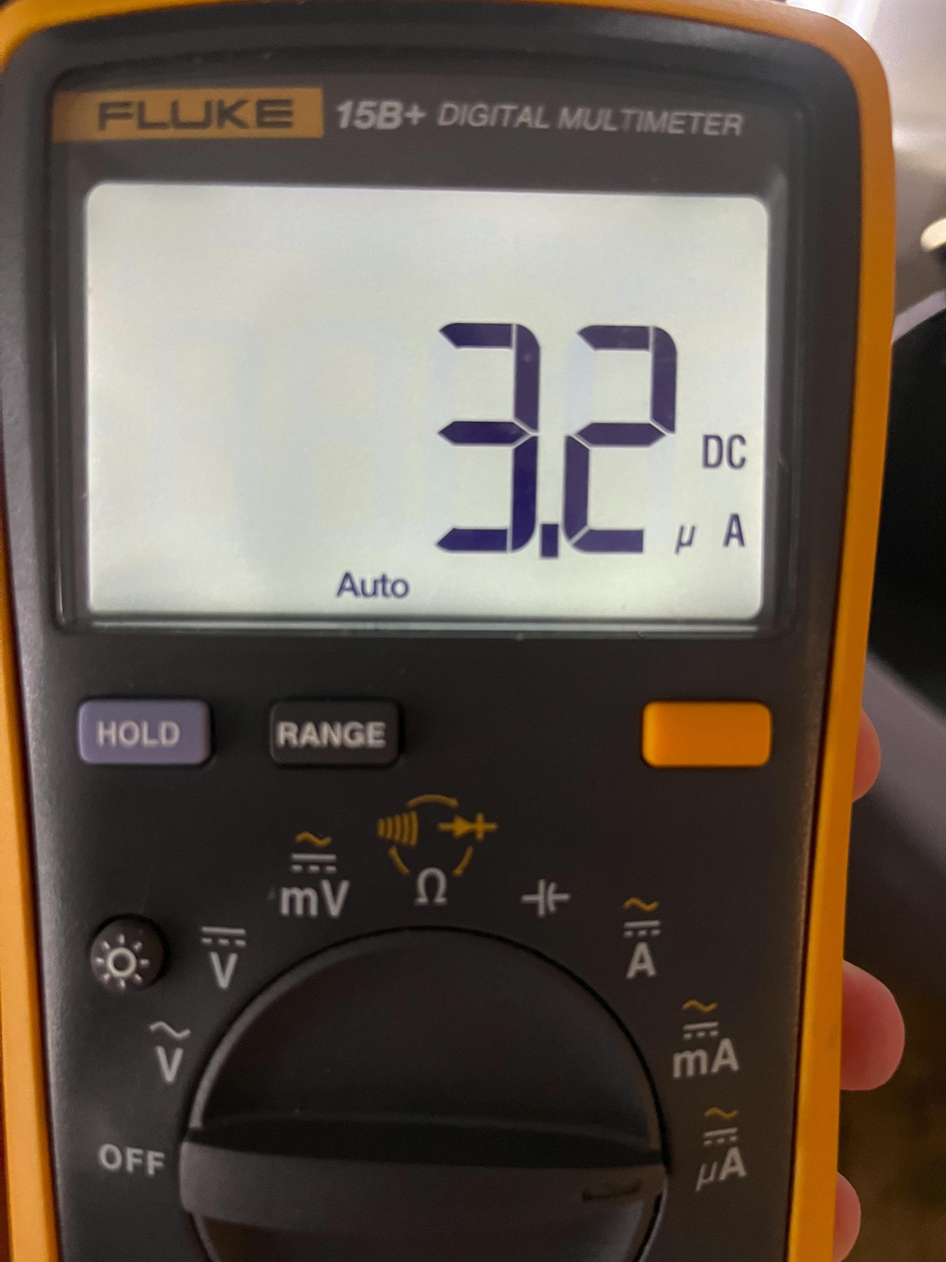
The use of sleep mode seems to have paid off, as I am now recording only a 3.2uA current draw from the EFM8SB1 when the CPU is in sleep mode:
![]()
On the other hand, I recorded a 1.35 mA current draw from the EFM8SB1 when the CPU was in idle mode:
![]()
Seems like sleep mode results in power consumption nearly 422 times lower than the idle mode!
-
Unoptimized firmware build #1
04/13/2025 at 15:08 • 0 commentsI banged out an unoptimized firmware build for implementing some light patterns and the power-saving mode. So far, we have for light patterns:
- Candlelight: bottom LEDs off, top LED flickers
- Solid: bottom LEDs on at 100% brightness, top LED flickers
- Blink (slow): bottom LEDs blink at a 1 Hz rate, top LED flickers
- Blink (fast): bottom LEDs blink at a 2 Hz rate, top LED flickers
- LED chaser
- Software flicker: all LEDs flicker at different offsets from the source RNG array; bottom LEDs flicker in software, top LED flickers in hardware with PCA0-based PWM generator
- Half-brightness: bottom LEDs are set to a reduced brightness through software PWM, top LED flickers
So far, I've implemented a crude power saving function that shuts off all LEDs and places the CPU in idle mode, where all interrupts may wake the CPU. Unfortunately, this is not ideal as the way I implement timekeeping is through Timer2 driven by the RTC crystal divided by 8, so the CPU will wake up every 1 second and need to be put back to sleep.
Ideally, I can place the CPU into sleep mode, where all peripherals and the core are both off. This would cut power consumption even more, but require me to re-implement several features:
- The button interfaces with the CPU through the INT0 interrupt, which is disabled during sleep mode. However, I can re-map the button to a port match interrupt on P0 and allow it to wake the CPU during sleep mode.
- Timekeeping is not implemented through the RTC timer right now, but I will have to do so if I want to allow the CPU to wake itself through RTC alarms.
This will require some re-writing of the code, so I'm going to dump what I have in my files for now.
-
Development Log 1
04/08/2025 at 22:44 • 0 commentsLast year, I developed a PIC16LF1823-based ornament that had several programmable LED patterns, had built-in timekeeping through a 32.768 kHz crystal, and was powered by a CR2032 coin cell. These things were cool and the PIC16LF1823 was an awesome device for this application, but I've always wanted to experiment with Silicon Labs' 8051-based microcontrollers. I'm very familiar with the 8051 architecture as I've done some work with the original Intel devices - I thought it would be pretty cool to work with modernized versions of them with modern peripherals so I thought a good test bed for them would be my battery-powered ornament concept. I already have a set of design files and C firmware for them, so it shouldn't be too much of an effort to port them to the EFM8. On top of that, the EFM8 had several features on paper that would allow me to reduce the component count on the PCB and retain much of the same functionality.
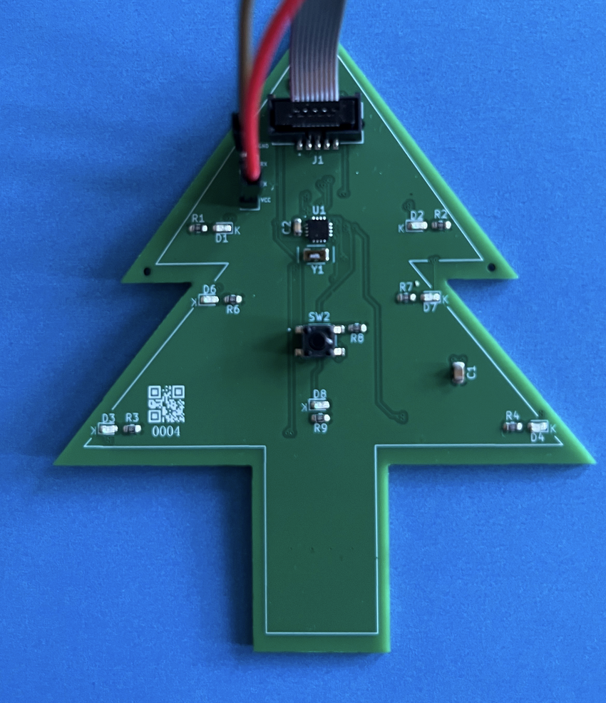
I based my design around the EFM8SB1 "Sleepy Bee" MCU, which has a very small QFN-20 package and boasts some great power consumption specifications, which is huge for an application relying on battery power. This time, I individually connected each LED to an MCU digital pin to directly drive them (the EFM8 is more than capable of this). Like last time, I hooked up a 32.768 kHz crystal for the RTC - but this time, I was able to omit the loading capacitors as the EFM8 as it has internal loading capacitors that can be configured to 16 different values. This time, I decided to use an SWD-style 1.27mm header for programming with my J-Link. The rest of the board used the old design - same button, same switch, same battery holder, more or less the same LEDs (though I added a few more).
I've been working on getting this thing working for a bit. I received two assembled PCBs last month but couldn't start development immediately for two reasons: 1) my development tools on hand wouldn't work and 2) I had to leave for a trip almost immediately upon receiving the boards.
More on the development tools issue: originally, I planned on debugging/programming these boards with a J-Link EDU I had on hand as it advertised the ability to program the EFM8/C8051-family devices from SiLabs. Unfortunately, this seemed to be inaccurate marketing as further investigation shows that the J-Link EDU does not support the C2 protocol used for flashing these devices. This left me in some trouble, as I had designed the pinout of the programming header to mate with a J-Link's interface. Unfortunately, I came to this conclusion after spending the better part of a night fiddling with Simplicity Studio, exasperated at its inability to work with the J-Link EDU to find my EFM8s.
I decided to try out a third-party programmer for Silicon Lab's 8051 devices. (from "Silicom Labs") as they were only $10 on eBay. However, these things come with a 2.54mm IDC header, which isn't exactly easy to mate these boards to. I had an issue: I had two complete PCBs that were otherwise fine and had an improper programming port pinout for this new debugger.
I had two options: design a custom cable using a larger 2.54mm IDC header on one side and a smaller SWD-style 1.27mm header on the other to mate with my PCB, or design a breakout board. I briefly investigated option 1 before deciding that building a breakout board might actually be cheaper and easier for me - and have more consistent results as I am not very confident in my handiwork when it comes to cables.
Before I left for my trip, I quickly designed and ordered a breakout board designed to interface the output of my third-party EC6 debugger with the programming port on my ornament PCBs. I decided to include two headers: one that was a simple 1-to-1 mapping of the larger IDC header to a smaller IDC header to allow me to use a 1-to-1 pinout on future designs and a second header that would allow me to program my ornament boards with an improper pinout. I also included breakouts of the 3.3V and 5V power outputs on this board - this was not a feature I saw on other 8051 debuggers so I decided it would be a boon for my efforts if I included the ability to power the boards with this breakout board (through a jumper wire).
I paid a grand total of $4 for these breakout boards and I was not disappointed. I was greeted with instant connectivity after plugging the other side of the third-party EC6 into my ThinkPad and firing up Simplicity Studio. Both programming and debugging work with this board - the 3.3V output of the debugger also works very well and is able to power the entire ornament PCB during debugging. The breakout board files are here: https://hackaday.io/project/202798-breakout-board-for-third-party-8051-debugger
So far, I have been working on developing firmware for the EFM8SB1. I've been working on code to activate all of the peripherals I'd need for an effective timekeeping ornament - so far, I've been successful at writing drivers for the RTC, timers, PWM output, and GPIO - of course, these weren't too bad as I have lots of experience with comparable MCUs, but these 8051-based MCUs have some quirks that take a while to understand if you don't look at the datasheet for a while (i.e. the Keil 8051 compiler is not C99 compliant, only C90, the way indirect accesses work with the RTC, and configuring the RTC oscillator).
Electronic Ornament 2025 with EFM8SB1 Sleepy Bee
This EFM8-based ornament is an improvement on my PIC16-based design from 2024

 I paid a grand total of $4 for these breakout boards and I was not disappointed. I was greeted with instant connectivity after plugging the other side of the third-party EC6 into my ThinkPad and firing up Simplicity Studio. Both programming and debugging work with this board - the 3.3V output of the debugger also works very well and is able to power the entire ornament PCB during debugging. The breakout board files are here:
  So far, I have been working on developing firmware for the EFM8SB1. I've been working on code to activate all of the peripherals I'd need for an effective timekeeping ornament - so far, I've been successful at writing drivers for the RTC, timers, PWM output, and GPIO - of course, these weren't too bad as I have lots of experience with comparable MCUs, but these 8051-based MCUs have some quirks that take a while to understand if you don't look at the datasheet for a while (i.e. the Keil 8051 compiler is not C99 compliant, only C90, the way indirect accesses work with the RTC, and configuring the RTC oscillator).