 Yannick (Gigawipf)
This project documents the process of building a high resolution linear scanning camera from scratch.
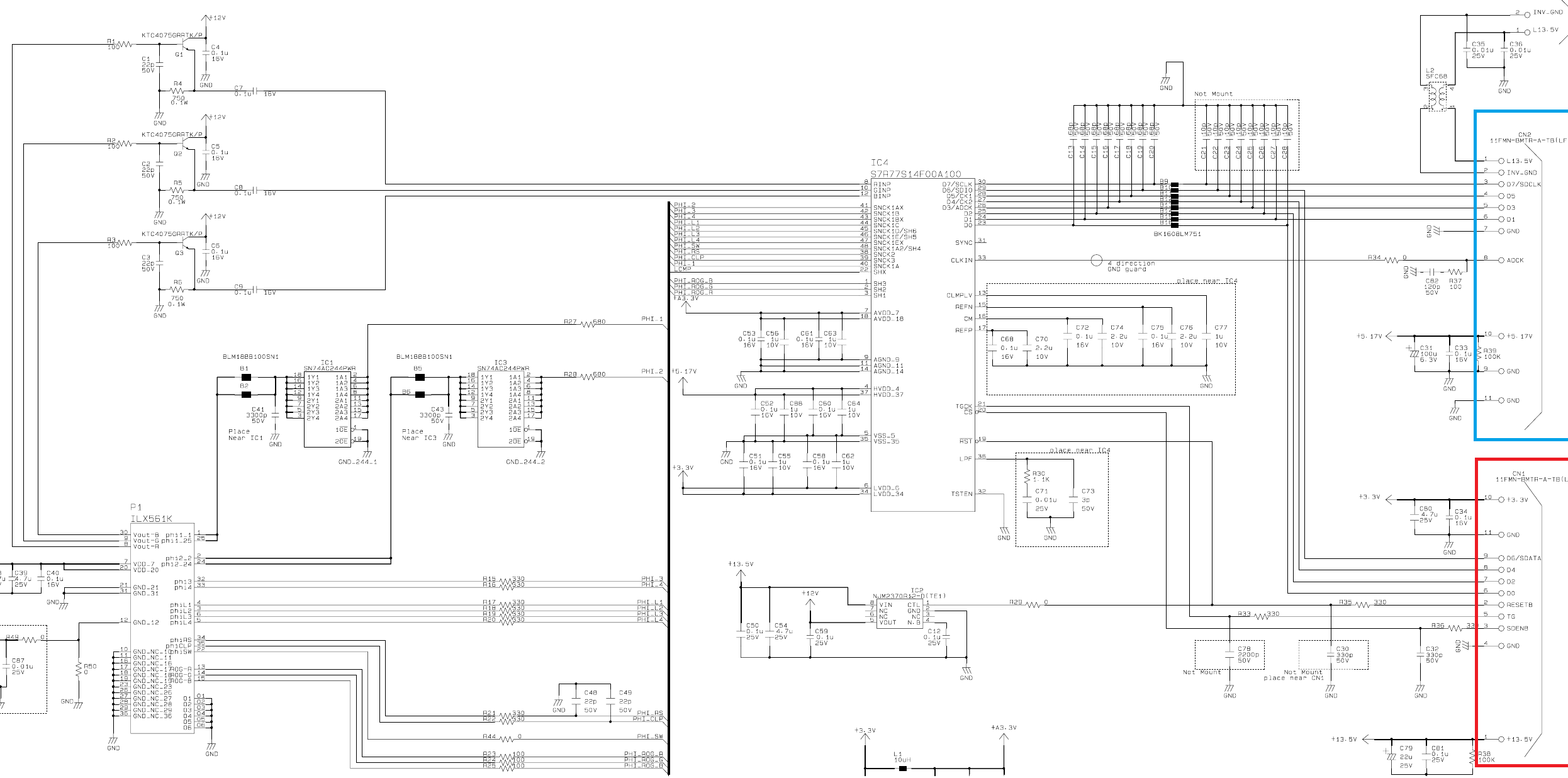
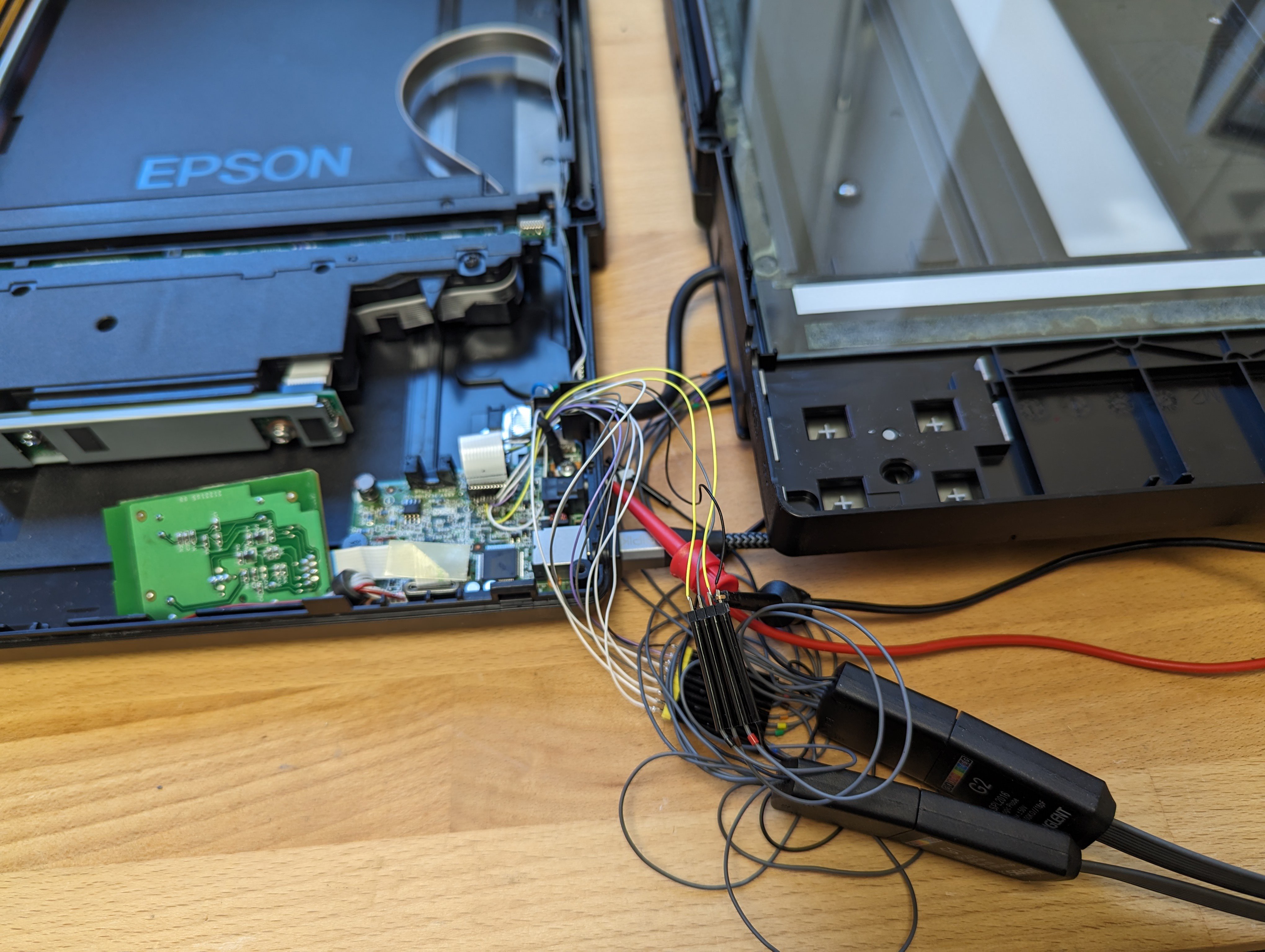
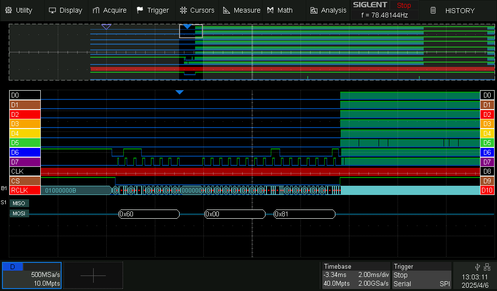
This includes reverse engineering the sensor and timing generator protocol, developing hardware and low level software for interfacing it, packaging it into a portable form factor and a user interface for standalone use.
While there are a few DIY projects converting CCD scanners into cameras most of them use the original scanner hardware and software essentially packaging a scanner into a new case and reducing the travel range with gears.
This usually works but comes with some limitations mainly in resolution, features and tricking the original scanner calibrations.
Instead this project aims to interface with the sensor assembly directly and replacing all other components of the original scanner with a custom implementation.
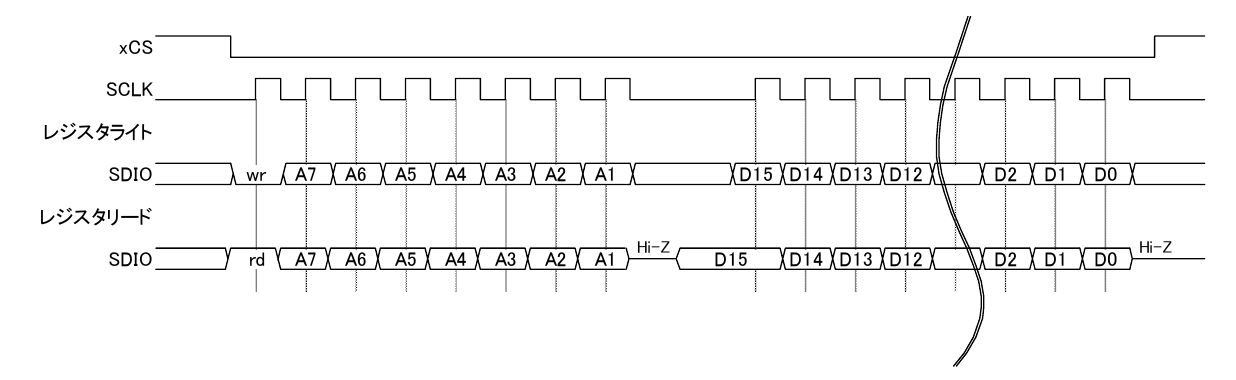
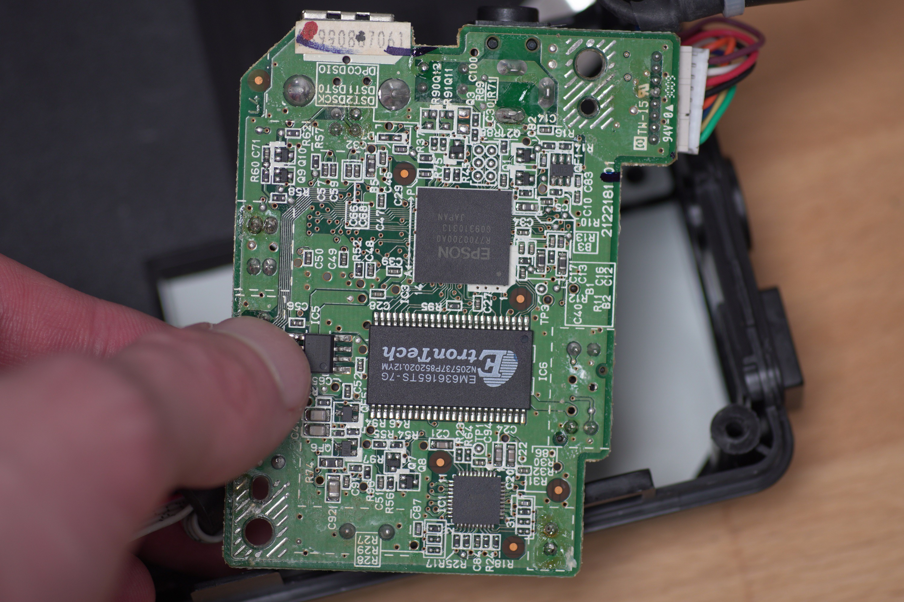
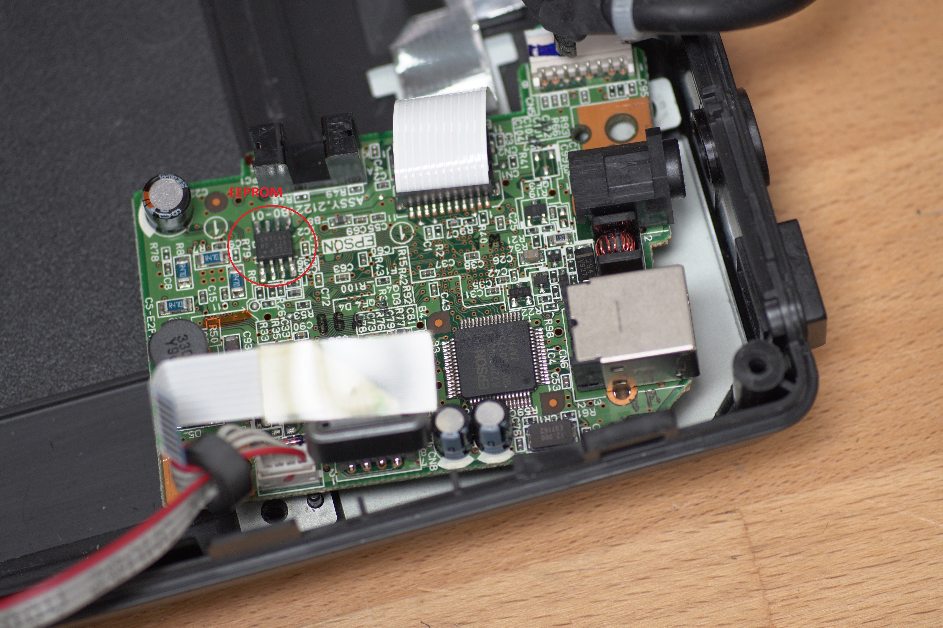
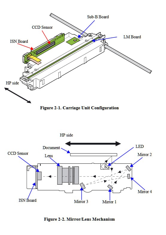
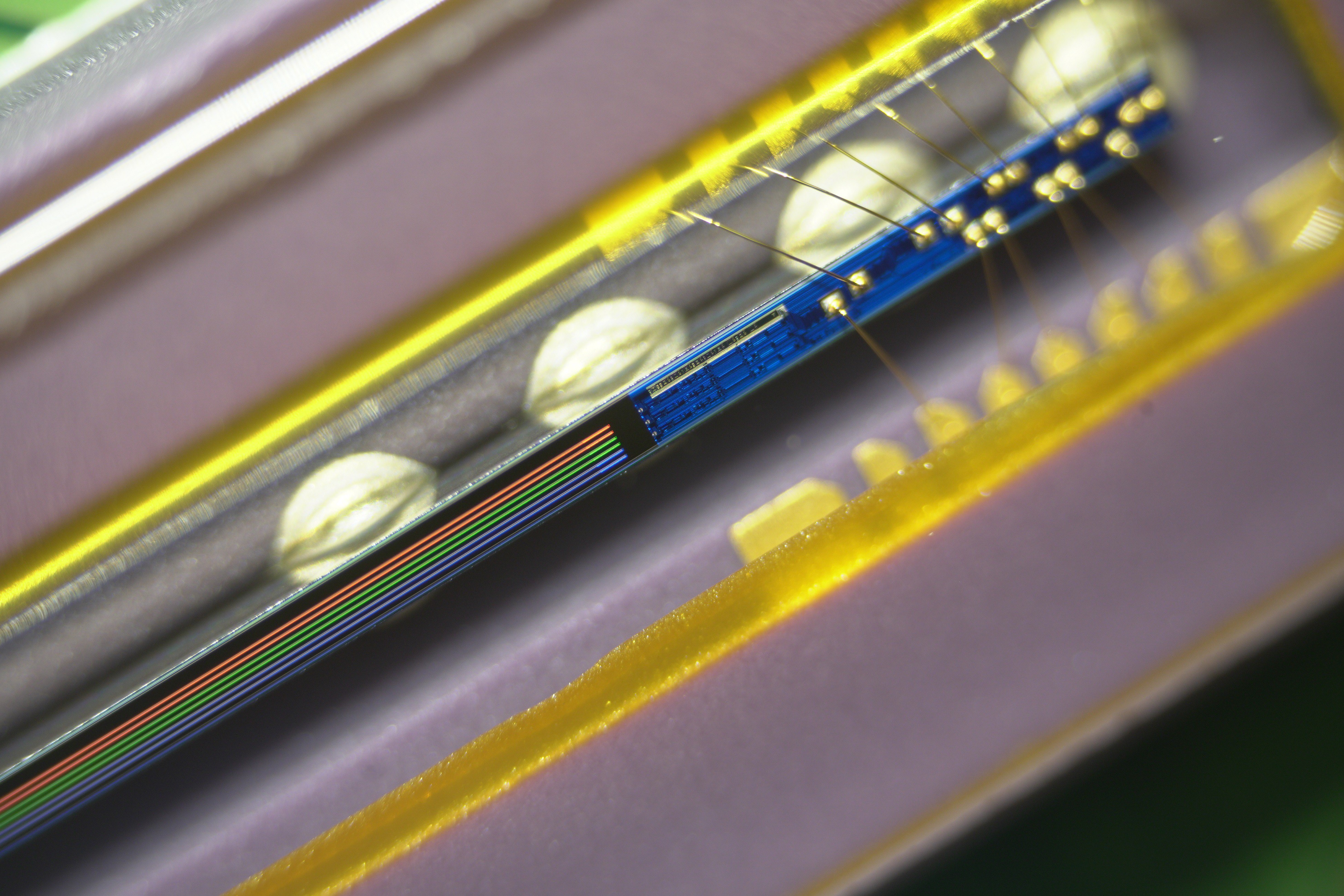
The Sensor used in these scanners is a 12 line (RGB x2x2 Main+Sub line) ILX561K CCD with 122,400 total pixels used with the S7R77S14F00A100 ADC+Clock gen chip.
By using all lines present an RGB image of over 3.2 Gigapixels (~80000x40160) with 16b true color could be achievable with a medium format 6x7 lens.
The development process and usage is documented in the project video:
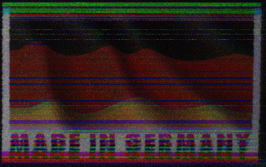
This is an example image in taken with the full sensor in 15360x40160 (600MP) 48bpp, downsampled to 8b and 1/4 resolution and heavily compressed:
And with a 200mm lens:
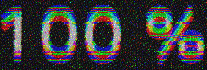
Detail shots:
Taken from this image:
More pictures in this flickr album


 Keith
Keith
 Gabriel Cséfalvay
 Lucy Fauth
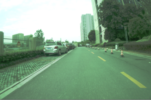
 Johanna Shi
Awesome project. thank you for documenting it and teh video. What did you use to create the user interface? Looks very slick.