-
Power measurements
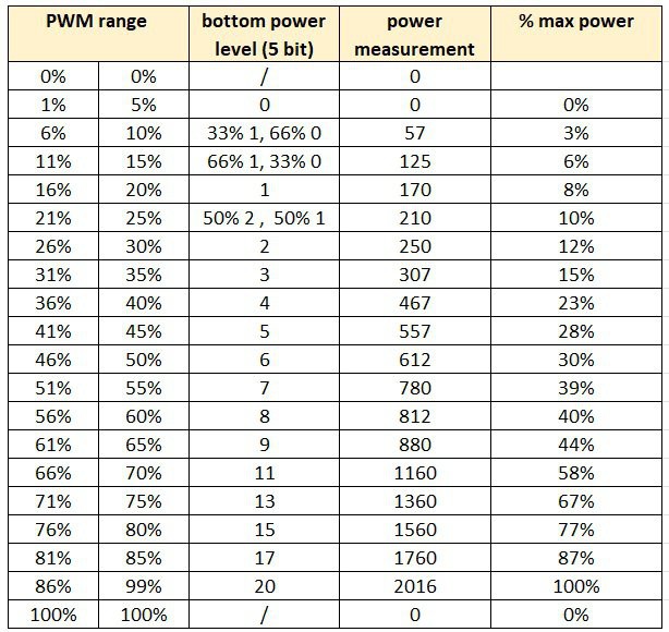
06/22/2025 at 17:37 • 0 commentsThe table below shows the mains power consumption of the induction cooktop at various internal power levels (5-bit values), along with how I mapped those levels to a corresponding PWM range.
To achieve power levels lower than the cooktop's minimum setting (Level 1 ≈ 170 W), I implemented time multiplexing for some PWM values. For example, a PWM value of 8% results in 5 seconds off followed by 10 seconds at power level 1, effectively lowering the average output.
Note that the power levels are neither linear nor logarithmic, but they are sufficiently consistent for the needs of my brewing application.
![]()
-
Embedded Code for Arduino
06/22/2025 at 15:57 • 0 commentsThe ATmega328PB on this board is programmed using the standard Arduino IDE.
To compile code for this specific microcontroller, you’ll first need to install the MiniCore board package, which adds support for the ATmega328PB and similar chips.
Once MiniCore is installed, burn the bootloader using the appropriate settings—after that, you're ready to upload the firmware as you would with any Arduino project.
See the included source code for details.
-
Circuit Schematic & PCB
06/21/2025 at 20:16 • 0 commentsSee the included schematic and PCB layout.
The circuit is intentionally simple, using components I already had on hand. The most critical design requirement was to maintain SELV (Safety Extra-Low Voltage) isolation between the opto-coupler input and the rest of the PCB, as well as the cooktop’s internal electronics.
The PCB was home-etched, which is the fastest and easiest method for a simple board like this. It features a single routed top layer and a solid ground plane on the bottom, which simplifies etching.
To protect against moisture or condensation, the board is finished with a conformal coating.
A 3.5mm jack is used as the input for the external PWM control signal.
For secure installation inside the cooktop, the PCB is mounted using a custom 3D-printed base.
-
Reverse engineering the serial protocol.
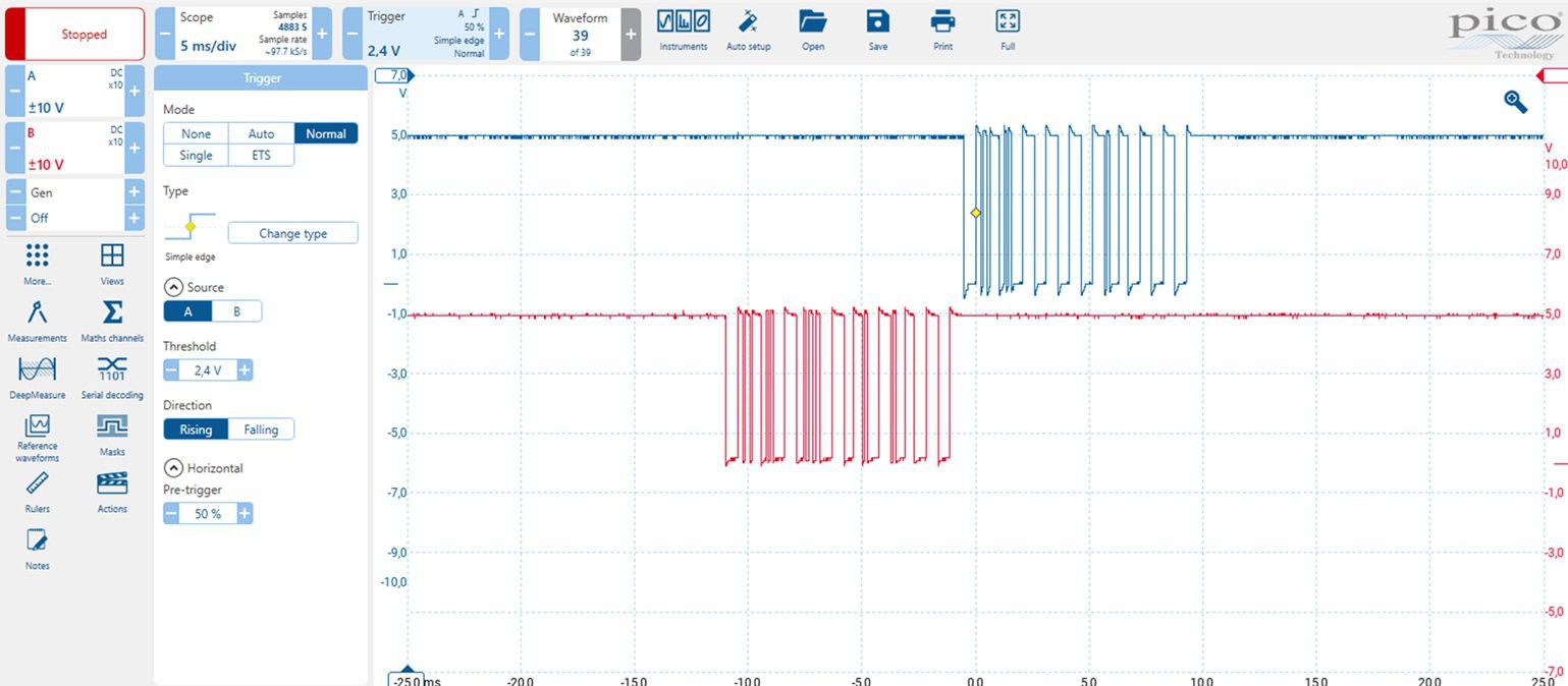
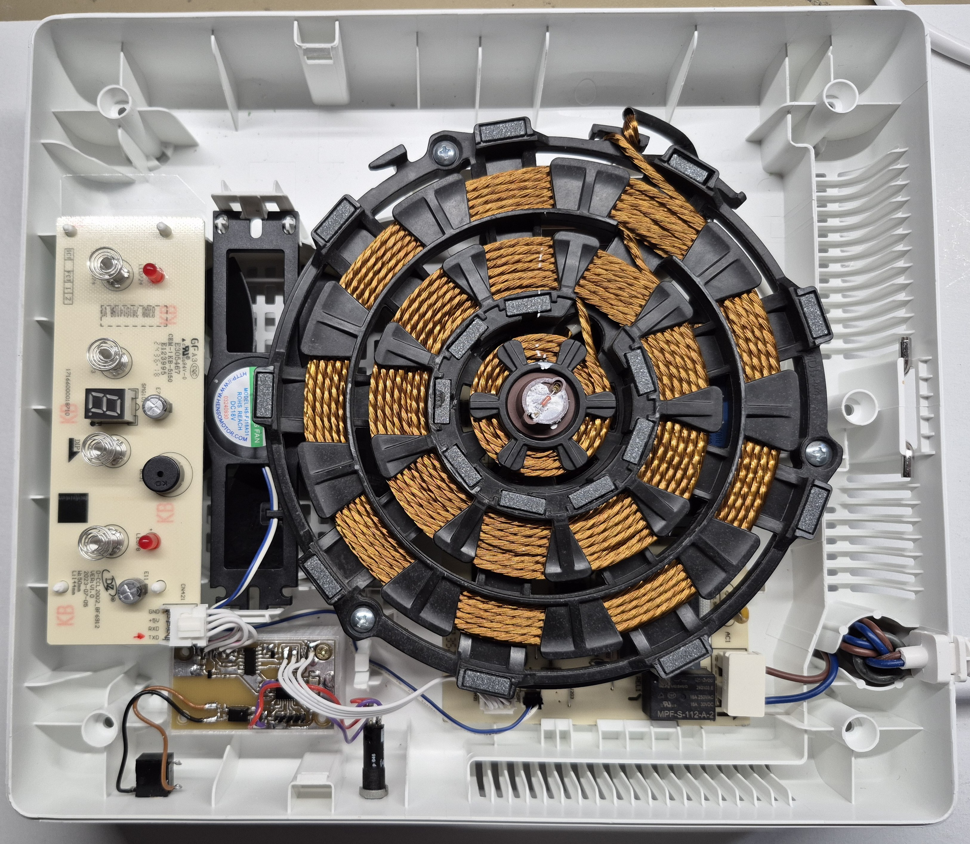
06/21/2025 at 18:03 • 0 commentsUsing an isolated oscilloscope, it became clear there's a master/slave serial communication setup between the front panel (master) and the power PCB (slave).
![]()
The communication uses standard 9600 baud, 8 data bits, no parity, 1 stop bit, and LSB-first format.
-
The front panel transmits a 10-byte message every 100 ms.
-
The power PCB responds with a message of equal length.
You might wonder why such a simple application needs this much data. The answer is probably a mix of redundancy/error correction, and the fact that modern designers don’t worry too much about a few extra bytes.
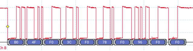
Analysis: Front Panel → Power PCB (Red Trace)
Here’s an example of the message when the power level is set to 0.
![]()
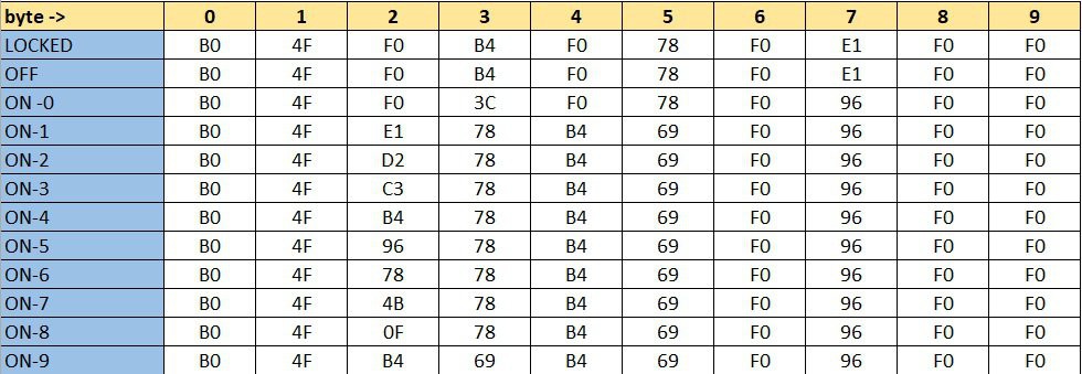
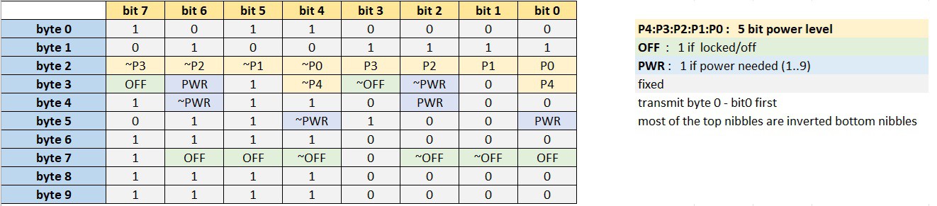
These are the telegrams corresponding to each possible front panel state (with byte 0 sent first).
![]()
I initially tried asking GPT-4 to decode the structure, but that didn’t lead anywhere useful. So, I went old school: pencil and paper. The result?
![]()
A lot of fixed values and redundancy, just as expected. For example: some values are inverted (~) as basic checksums.
There are 5 bits used to encode the power level, allowing for up to 32 distinct values. This means the system is technically capable of finer power control than what the front panel offers, which only allows selection of levels 0 through 9.
However, there are two important limitations:
-
The lowest power level available via the protocol still corresponds to front panel level 1, so there's no way to achieve a power output lower than that baseline.
-
Interestingly, front panel level 9 corresponds to a power level value of 20 (decimal) in the protocol, indicating that only a portion of the available range is used.
Analysis: Power PCB → Front Panel
This direction was a bit trickier. Some of the values changed with every transmission.
Below is a capture of 15 sequential messages ( OFF state).![]()
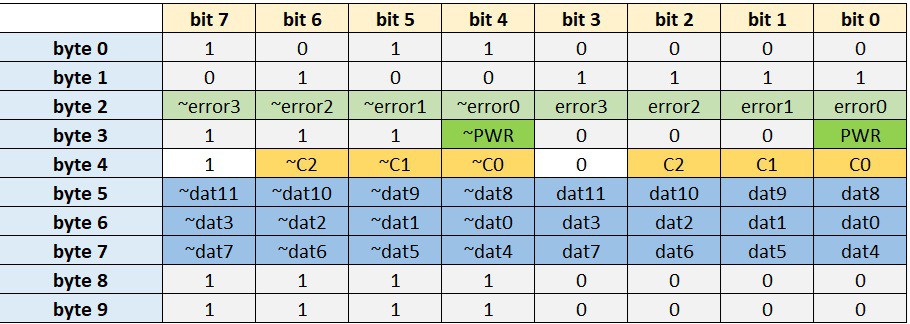
After a beer and some focused thinking, here's what I figured out:
![]()
-
The 4 error bits appear to encode error conditions.
-
For example, error1 seems to indicate “no pot detected” on the cooktop.
-
I didn’t dig much deeper, since the PWR bit turned out to be a reliable indicator of whether power is being delivered or not.
-
Parameter Cycling Logic
One part of the message changes continuously: every transmission includes one of five different data parameters. This is controlled by 3 bits C2:C1:C0, which cycle through: 0 → 1 → 2 → 3 → 4 → 0 → ...
Each parameter is sent as a 12-bit value dat11:dat0
Reverse-Engineering the 5 Data Parameters
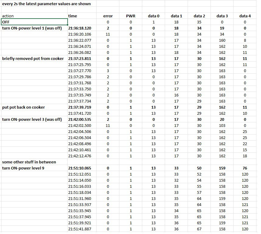
After some experimentation, here’s my best guess at what each parameter represents:
![]()
Parameter Likely Meaning
Data 0 : Unknown
Data 1 : Temperature of something
Data 2 : Temperature of something else
Data 3 : Voltage indication ? (drops slightly as power increases)
Data 4 : Power indicationHowever, my interface doesn’t depend on these values. It simply checks that the PWR bit is in the expected state (i.e., ON when power is requested).
It’s worth noting that the power PCB has solid self-protection features. For example, it automatically drives the cooling fan when necessary—independent of external control.
-
Conceptual Solution
06/21/2025 at 15:07 • 0 commentsThere were two main approaches I could take:
Option 1: Hijack the Capacitive Buttons
This involves adding electronics that take over the touch buttons. Since the device behaves autonomously (e.g., it automatically switches off after sitting at power level 0 for a while), I’d also need to read all the LEDs—including the 7-segment display—to monitor its current state and react accordingly.
Pros:
-
Straightforward—no need to reverse-engineer the communication protocol
-
Built-in safety features remain fully active
-
The display still shows the current power level
Cons:
-
Requires careful tuning to reliably trigger the touch sensors
Option 2: Intercept the Communication Between Control and Power Boards
This means placing a microcontroller between the control PCB and the power PCB. It can pass through normal communication during manual use, and take over when automated PWM control is needed.
Pros:
-
Offers more direct and flexible control
-
Potential for finer-grained control beyond the default 0–9 power levels
Cons:
-
Requires reverse-engineering the communication protocol
-
Need to fully understand the built-in protection mechanisms
At the time, Option 2 seemed the most promising—or at least, the most fun from an electronics perspective—so I went with that.
Here’s a photo of the final working setup. More details to follow!
![]()
-
-
⚠️ Safety Disclaimer
06/21/2025 at 14:05 • 0 comments⚠️ Disclaimer
This project is provided for educational and experimental purposes only.
Modifying electrical appliances—especially high-power devices like induction cooktops—carries significant risk, including electric shock, fire, injury, and property damage.
The author is not responsible for any injury, damage, loss, or legal consequences resulting from the use or misuse of this information.
If you choose to replicate or adapt this project, you do so entirely at your own risk. Ensure all work complies with your local electrical safety regulations and building codes.
Do not attempt this project unless you are competent and qualified to work with high-voltage electrical systems.
This project is not affiliated with, endorsed by, or supported by IKEA in any way. All product names and trademarks are the property of their respective owners.
DIY PWM-Controlled IKEA TILLREDA Induction Cooktop
Modifying a 2kW induction cooktop for precise control via PWM, enabling integration into an automated beer mashing and cooking system.