Close
0%
0%

PVCSub: A Submarine from the Plumbing Aisle

I built a DIY submarine that any high school student can make!

Similar projects worth following

DIY PVC Submarine with Ballast and Jet Propulsion

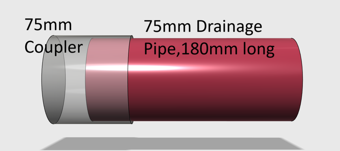
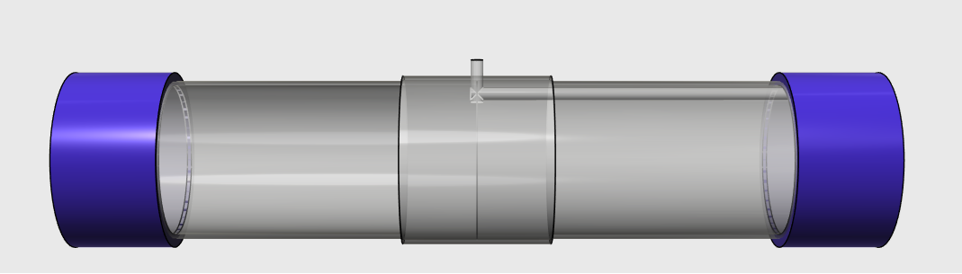
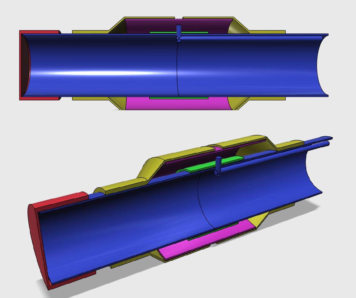
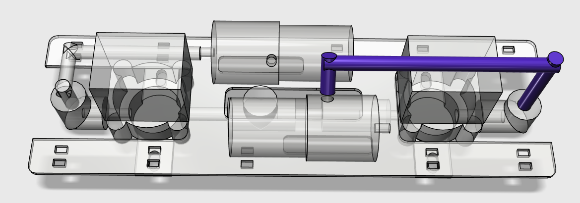
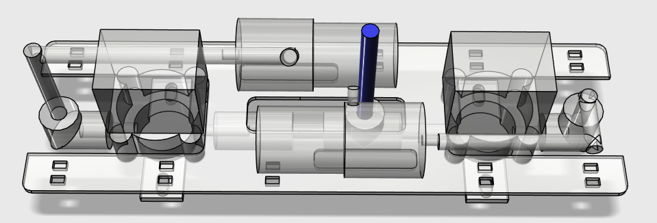
This is a fully functional model submarine built using common PVC drainage pipes. Weighing about 2.4 kg in air, the submarine is designed for simplicity, ruggedness, and full manual control — making it a great exploration of underwater mechanics using off-the-shelf parts.

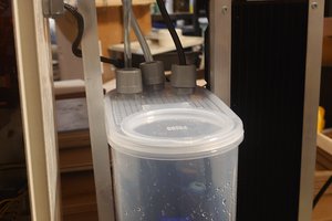
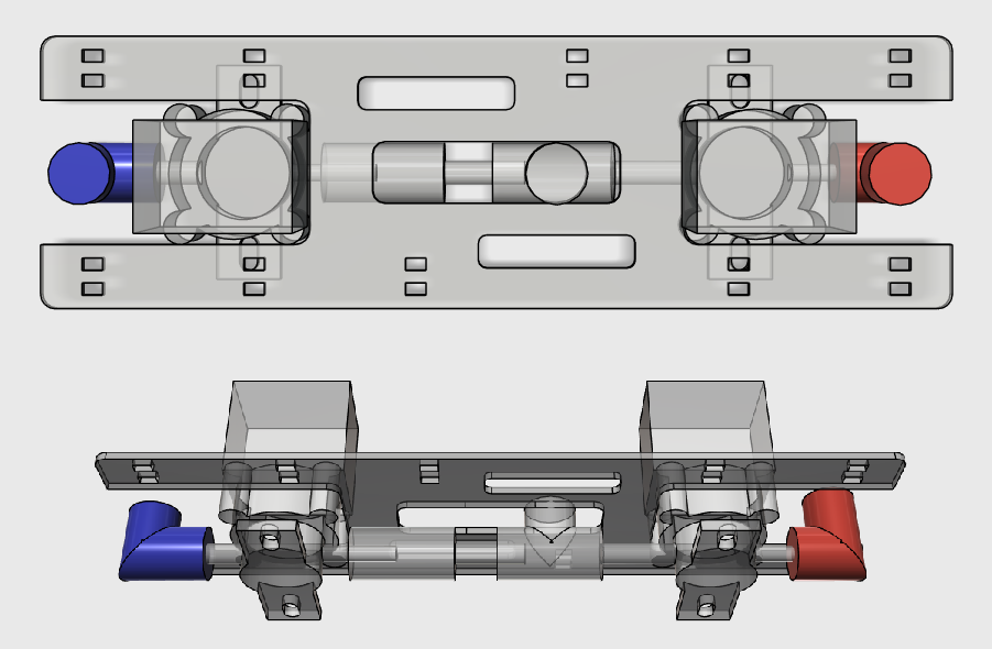
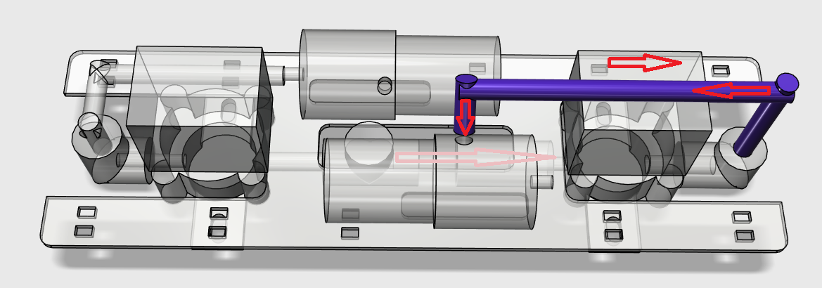
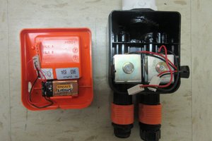
Ballast Control System

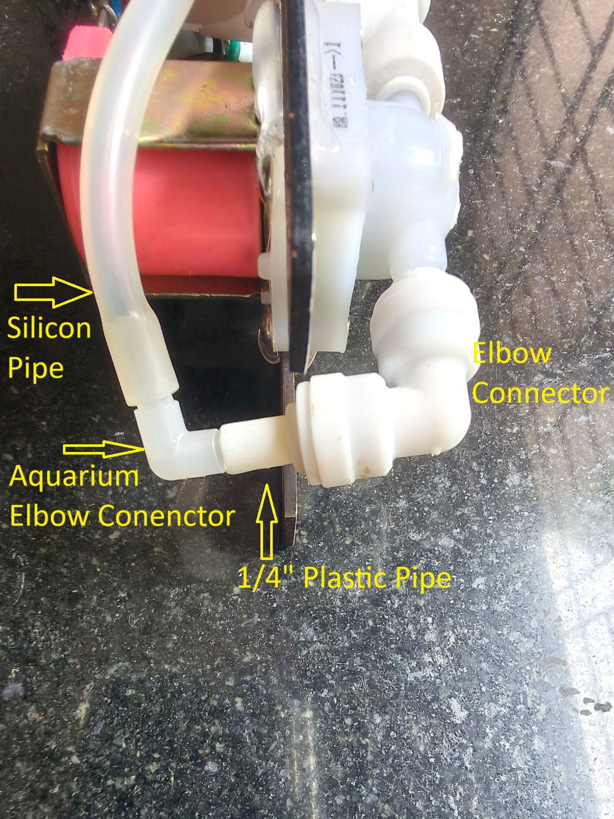
The submarine’s dive and surface capability is managed via a dual-pump ballast control system:

  • Diving: One pump evacuates air from the ballast tanks, storing it inside the sealed body of the submarine. As air is removed, water enters the ballast chambers, increasing weight and causing the sub to sink.

  • Surfacing: A second pump returns the stored air into the ballast, displacing the water, and decreasing the overall density of the sub — allowing it to rise.

This air-water exchange system avoids the need for compressed gas tanks or valves, and keeps everything electric and easily reversible.

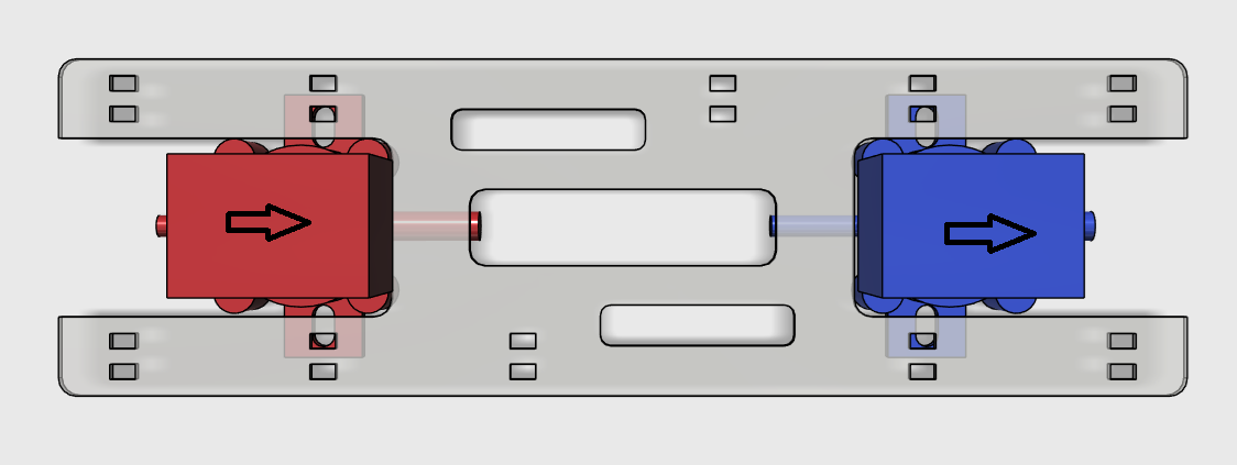
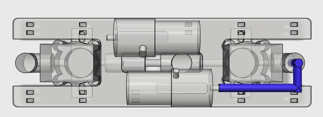
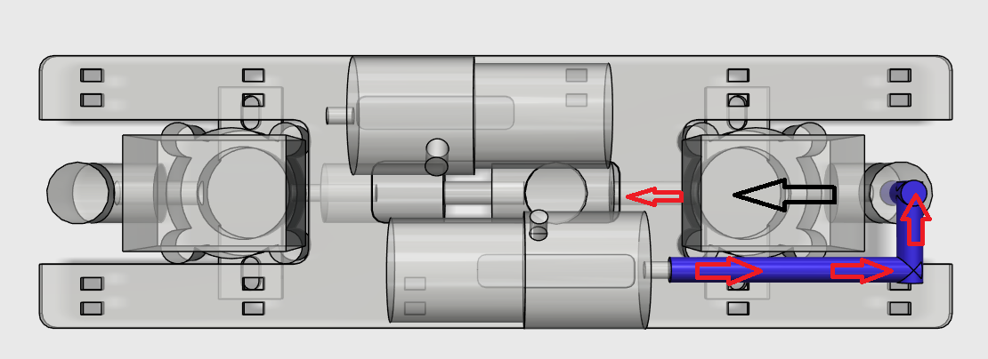
Propulsion & Steering

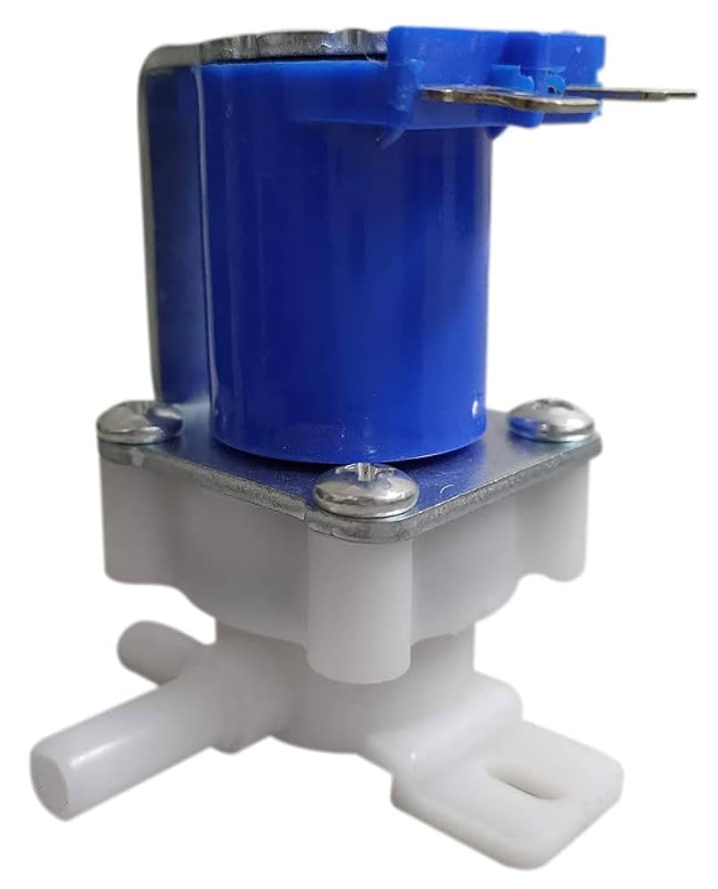
Three 12V water pumps located at the rear of the submarine provide propulsion:

  • The center pump provides forward thrust.

  • The side pumps are used for directional control, allowing for basic steering by turning left or right through differential thrust.

Control Interface

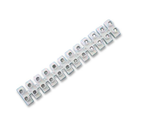
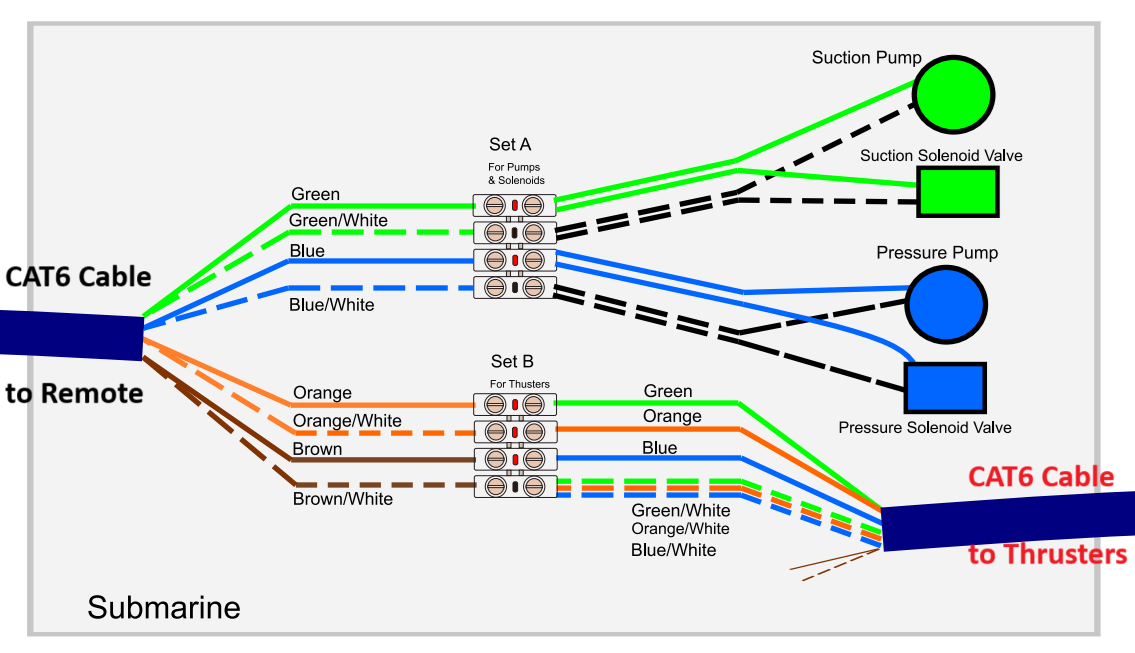
All functions are controlled through a custom-made wired remote using a CAT6 cable that connects to the submarine:

  • Standard DPDT switches control each of the pumps.

  • Each device runs on 12V, allowing compatibility with common battery setups and switches.

  • The manual interface emphasizes simplicity and real-time human control, perfect for testing and tweaking underwater behavior.

Submarine Wiring Connections.pdf

Adobe Portable Document Format - 311.70 kB - 07/15/2025 at 05:57

Preview

Terminal Block.png

Portable Network Graphics (PNG) - 97.47 kB - 07/15/2025 at 05:57

Preview

75mm Sub Control Plate.pdf

This is the 75mm control plate, required for laser cutting. Process this in 2mm or 3mm Mild steel.

Adobe Portable Document Format - 3.90 kB - 07/10/2025 at 06:08

Preview

WhatsApp Image 2025-07-07 at 16.14.07_eb9f9193.jpg

The finished submarine

JPEG Image - 96.16 kB - 07/07/2025 at 10:45

Preview

41qtMKaTJpL._UF1000,1000_QL80_.jpg

This a 12v Solenoid Valve, which comes from an water filter. It is sold as a spare part.

JPEG Image - 31.67 kB - 07/08/2025 at 10:13

Preview

View all 12 files

  • Making the Electrical Connections

    Rupin Chheda07/14/2025 at 17:00 0 comments

    We are using a CAT6 Cable for transmitting power! Couple of reasons

    1) It has 8 wires in one cable! 

    2) The wire size is good enough to transmit 0.5A of current, enough for most of our devices. 

    3) Cheap and available easily anywhere. 

    4) Wire colors are all standard, so easy to communicate. 

    We use a Wire Terminal block to make our connections on the submarine side. 

    A schematic of the connections is available in pdf here.

    The connections of the CAT6 Cable ( coming from the remote, left of this image). 

    The 8 wires are split as Set A and Set B. 

    Set A consists of the green and blue pairs

    Set B consists of the Orange and Brown Pairs

    In Set A the Connections are as follows in the table below. 

    WireDevice Connected toVoltage
    Solid Green Suction Pump ( + terminal)12V
    Suction Valve ( Any terminal)
    Solid Blue Pressure Pump ( + terminal)12V
    Pressure Valve ( Any terminal)
    Green/White Suction Pump ( - terminal)0V
    Suction Valve ( Any terminal)
    Blue/White Suction Pump ( - terminal)0V
    Suction Valve ( Any terminal)

    In Set B the Connections are as follows in the table below. 

    WireDevice Connected toVoltage
    Solid OrangeLeft Thruster Any Terminal12V
    Solid BrownRight Thruster Any terminal12V
    Orange/WhiteForward Thruster Any terminal12V
    Brown/WhiteAll Thrusters ( remaining terminal)0V

    A piece of CAT 6 cable, about 2 ft long is cut, and as shown below the Set B terminal block has connections to the thrusters. The wire originates from the submarine, comes out of the water tight compartment, and connects to the thrusters at the back of the submarine. 

    We will cover the connections of the remote in a future log. 

  • Making the Thruster Mount

    Rupin Chheda07/10/2025 at 07:01 0 comments

    We use a 75mm pipe, of length 20cm to make a mount for the propulsion and steering thrusters. 

    Use a strip of paper and wrap it tightly along the circumference of the pipe. Tape the two ends of the paper strip. 

    You now have a reference of the pipe circumference. Fold this ring 4 times, to get a total of 8 creases. This provides an accurate measure of 8 parts we divide one end of the pipe in. 

    Once you have marked the pipe, cut out 6cm long strips in alternate fashion as shown. 

    Use a heat gun to soften the strips, then form it around the end cap of the submarine body. 

  • Building the Submarine Body

    Rupin Chheda07/09/2025 at 15:55 0 comments

    The Body of the Submarine comprises of the Water Tight Compartment, which is made up of 75mm drainage pipe, and the Ballast, made out of 110mm pipe. 

    We build the submarine inside out, ensuring every joint made is water tight and leak proof under pressure.  The ballast control board can help inject air at high pressure into any volume, and we can test for leaks by immersing the structure in water. 

    Step 1

    Get hold of the 75mm coupler and a 180mm long 75mm pipe. Join both of them using PVC cement. 


    Step 2

    Drill a hole exactly in the center of the coupler. Use a 4mm or a (5/32)" drill bit. 

    Step 3

    Create the air Inlet pipe using a 90 degree elbow connector and a silicon pipe. This is the path the air takes to and from the ballast. 

    Step 4

    Insert this bent connector from inside the 75mm into the hole just created. Orient it such that the flexible pipe aligns itself in the direction of the 75mm pipe. Use CA glue to hold it in place. Make sure the silicon pipe hugs the inside of the 75mm pipe. 

    Try and push this connector inside, it should not budge, if it comes off, repeat step 4. It is important that this connector be in this place firmly. We will not get a chance to fix this connector again. 

    Step 5

    Glue another 180mm long, 75mm pipe to the other side. 

    Step 6

    The water tight compartment is completed. Use two 75mm rubber caps to close both ends of the pipe. Connect a spare piece of silicon tubing and blow into the pipe. Immerse in water ( you can use a big enough bucket) and check if there is a leak. Fix all joints with two part epoxy until no more air escapes.  

    Step 7

    Once the tests are completed that no more air leaks from any of the joints, we can start building the ballast. 

    The ballast is made up of  two inverted reducers which have been modified to slide on top of the 75mm pipe freely. 

    Fit the first reducer as shown. Its edge should just stop close to the center of the 75mm coupler. 

    Once you are confident its placed right, make sure you fit it permanently using pvc cement. We will test for air tightness once the entire ballast is completed. 

    Step 8

    Close the left end of the 75mm pipe with a 75mm end cap. This will be glued with pvc cement. 

    Step 9

    Lets start closing the Ballast. Fit a 130 mm long,  110mm pipe into the reducer as shown. Glue this with PVC cement. 

    Step 10

    Slide in the other reducer from the opposite side, closing the ballast. 

    Step 11

    If you notice, the flexible silicon pipe opens into the ballast. You can pump air into the ballast, with the other end of the silicon pipe to check for leaks.

    Close all leaks with 2 part epoxy. 

    Cross Sectional View

    In this view, we can clearly see the Ballast volume. Its the area between the purple cyclinder and the dark blue cylinders. 

    The pipe pops out of the dark blue cylinder and appears in the ballast. 

    How will the water enter the ballast?

    We will make a hole in the ballast at the bottom, diametrically opposite the small silicon pipe's entry into the ballast.  This way, the water fills up the ballast from the bottom, and by the time the submarine has sunk, only 2/3rd of the ballast volume is filled up. 

    We dont want to make this hole until all tests of pressurisation and leak-proof-ness have been completed. 

  • Assemblying the Ballast Control Board

    Rupin Chheda07/08/2025 at 13:35 0 comments

    The Ballast Control Board is a plumbing project. In this board, there is a steel plate which is laser cut and everything mounts to it.  Lets see this process step by step. 

    This is the plate for the Ballast Control. It measures 220mm x 66mm, small enough to fit in a pipe of 72mm ID.  

    You can find the pdf for this design in the files section. Download it, and get it laser cut on 2mm steel. 4mm acrylic is also good enough. Do not use MDF.

    Step 2: Install the Solenoids. 

    The Solenoids are electrically activated "air switches", that stop or let air flow. The solenoids are one way-valves too, they only allow a fluid ( air or water) to flow in one direction, often marked with an arrow on the body of the solenoid. We have to install the solenoids so that the arrows point in same direction. 

    The reasons will become evident to us in the steps further. 

    Step 3: Connect the Outlets with Push Fit Connectors

    • Green is a T connector. The vertical outlet of the T is where the air will be moving in or out of the valves. 
    • Red is a Straight Coupler. 
    • Blue is 1/4" pipe which you can push fit into the T and Staright Coupler.

    To understand the image better, we must know that only one solenoid is on at any point in time. 

    If you follow the arrows, it becomes obvious that the solenoid on the left of the image allows air to flow towards the T connector, hence it allows the air to flow out. 

    The solenoid on the right will allow flow of air to be away from the T connector and towards the right. 

    By placing the solenoids this way, we have achieved the air to flow towards and away from the T connector. 

    Step 4: Connect the Elbow Connectors on the solenoids

    Push fit the Elbow Connectors. 

    The Pumps will be connected to the Elbow Connectors next. 

    Step 5: Install the Pumps. The are zip tied to the plate. 

    You will notice the pump has an inlet and an outlet. The inlet is on the side of the pump, the outlet is in the front of the pump. 

    Air will be sucked through the inlet, and exits out the outlet. 

    You can inflate a balloon, if it was connected to the outlet. 

    Step 6: Connect the Infator Pump

    Use a Flexible Silicon Tube and Connect the Outlet of the pump to the inlet of the solenoid. This is where the elbow Connector is joined..

    The red arrow represent the direction of the air flow when the pump and the solenoid are turned on.  

    Step 7: Connect the Deflator Pump 

    Use a Flexible Silicon Tube and Connect the Inlet of the deflator pump to the inlet of the solenoid. This is where the elbow Connector is joined..

    The red arrows represent the direction of the air flow when the pump and the solenoid are turned on. 

    Step 8: Connect the Outlet Pipe


    This ends the construction of the Ballast Control Plate. We will move on to testing this by soldering wires to all the devices one at a time. 

View all 4 project logs

Enjoy this project?

Share

Discussions

Does this project spark your interest?

Become a member to follow this project and never miss any updates