Tim S
Tim S-
Custom Case and PCB
08/15/2025 at 20:21 • 0 commentsLots of progress since the last update. I designed a case and a custom PCB, made a couple dumb mistakes, and fixed most of them (albeit in a slightly bodgey way).
Custom PCBs from PCBWay
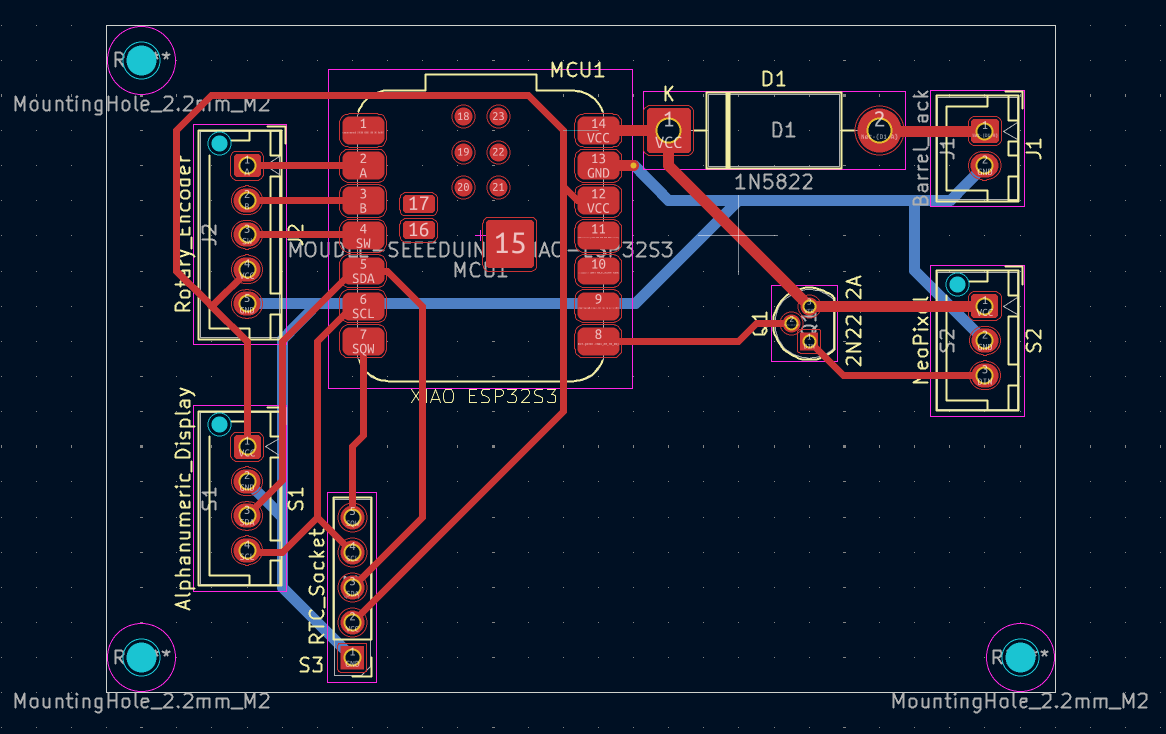
First thing I did after the last update was work on a schematic and PCB design. I put the schematic together in KiCad; mostly just breaking pins out into connectors for the various other components, but also a transistor to use as a logic level converter (remember that dumb mistake thing?). PCBWay was kind enough to reach out and offer to supply the PCBs for this project for free.
![]()
The process was super quick and easy; with the design complete, I just exported the gerber files and uploaded them to PCBWay. This is a fairly basic 2-layer PCB, but the options available on their site have me excited to try projects that would justify something more complex. A couple weeks later, the PCBs arrived and I did some quick testing to make sure they were working as expected - all perfect, thanks PCBWay! I look forward to continuing to work with them in the future on this and other projects.
Initial Assembly
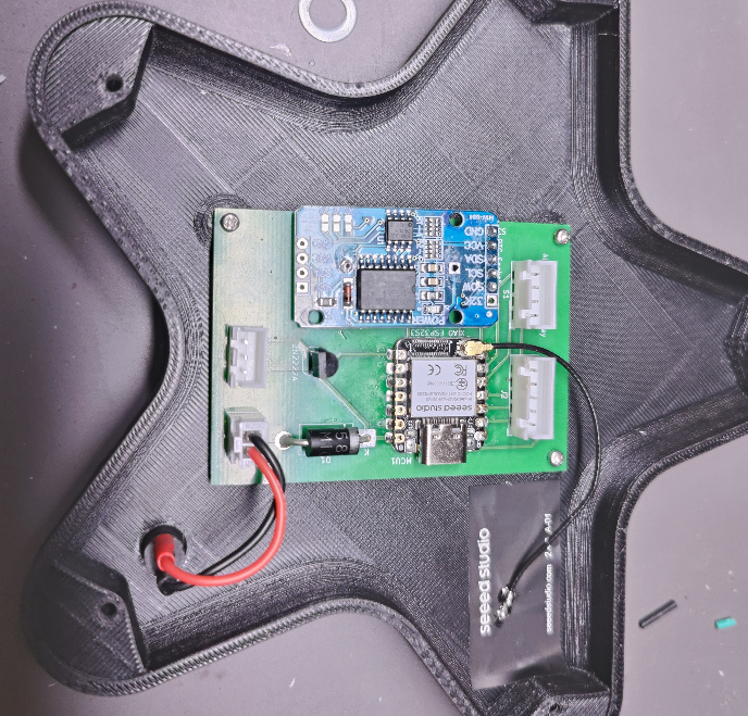
The testing done, I soldered the components onto one of them.
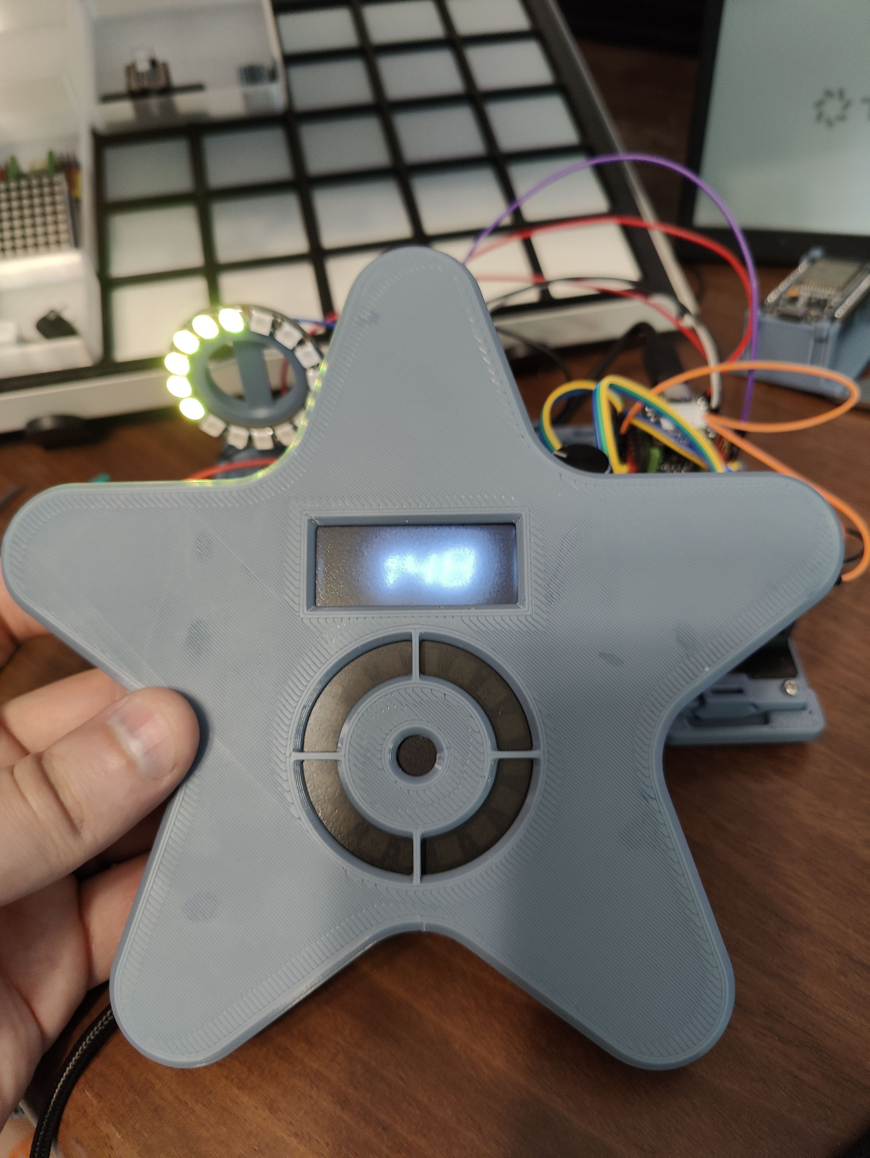
![]()
The front of the case was completed as well; I used a weird mix of heatset inserts of various sizes, and some manually threaded holes. This was done mostly so I could experiment and see what process I liked best, and for V2 I’m hoping to standardize onto a single method/piece, to simplify assembly. The diffuser is a small piece of translucent gray acrylic that I drilled a hole in and sprayed with a satin varnish to make a little more opaque.
![]()
Debugging and Re-Assembly
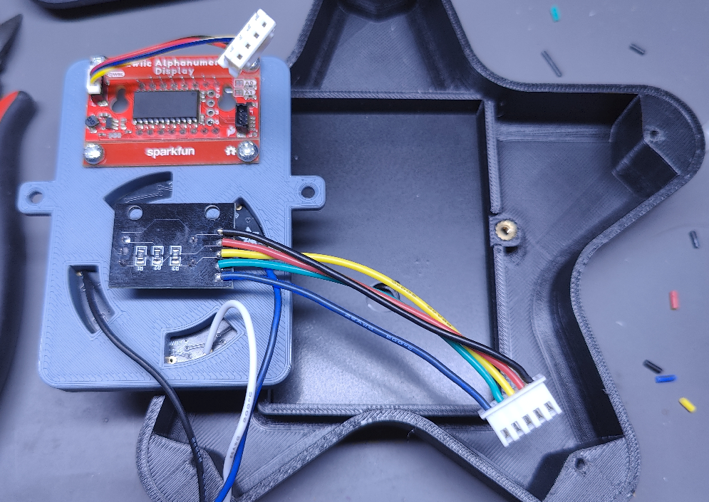
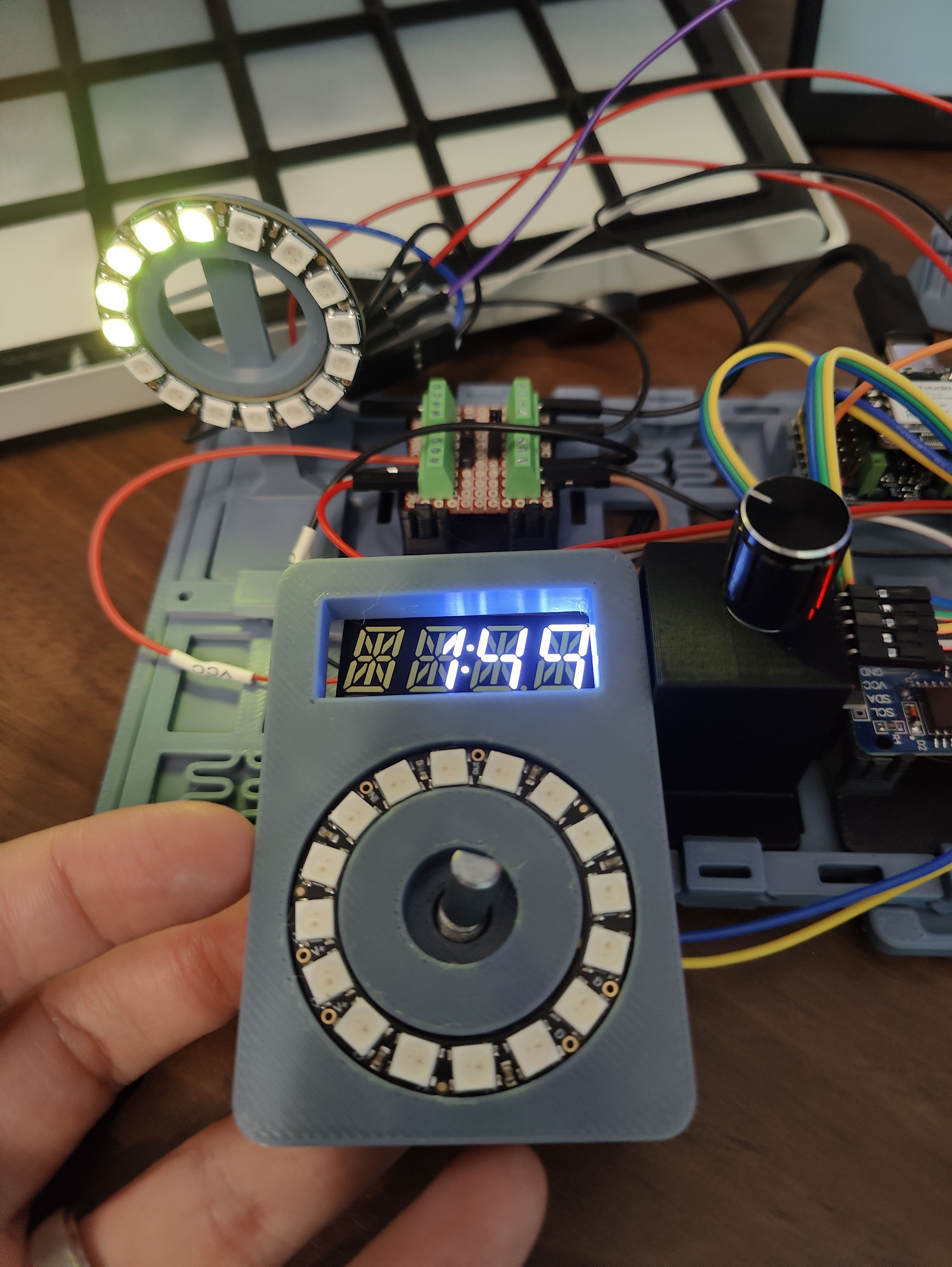
With everything assembled… nothing worked. According to some serial debugging, the I2C addresses I was expecting to find the display and RTC at were missing, and nothing I did could get the LED ring to light up. The I2C issue ended up being a loose connection, which was fortunately quite easy to resolve. The LED Ring… that was from me trying to cheap out and use a single transistor like a logic-level converter. I’m looking into a better way to do it in the future, but for the time being, I just manually wired in a 4ch logic-level converter I had on hand. A bit wasted here, but it works.
![]()
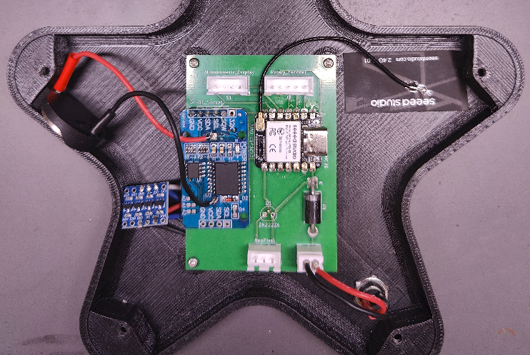
After that it was just a matter of reassembly… and then discovering that I’d broken the square-wave interrupt from the RTC somehow. Honestly, after checking the connections with a multimeter and watching both the I2C and SQW signals with a logic analyzer, I’m not sure what I did. But I appear to have burned it out somehow. Fortunately, the rest of the RTC is working just fine, so for now I’ve just switched the code over to poll roughly every 1s based on the internal clock instead of more exactly every 1s based on the SQW output.
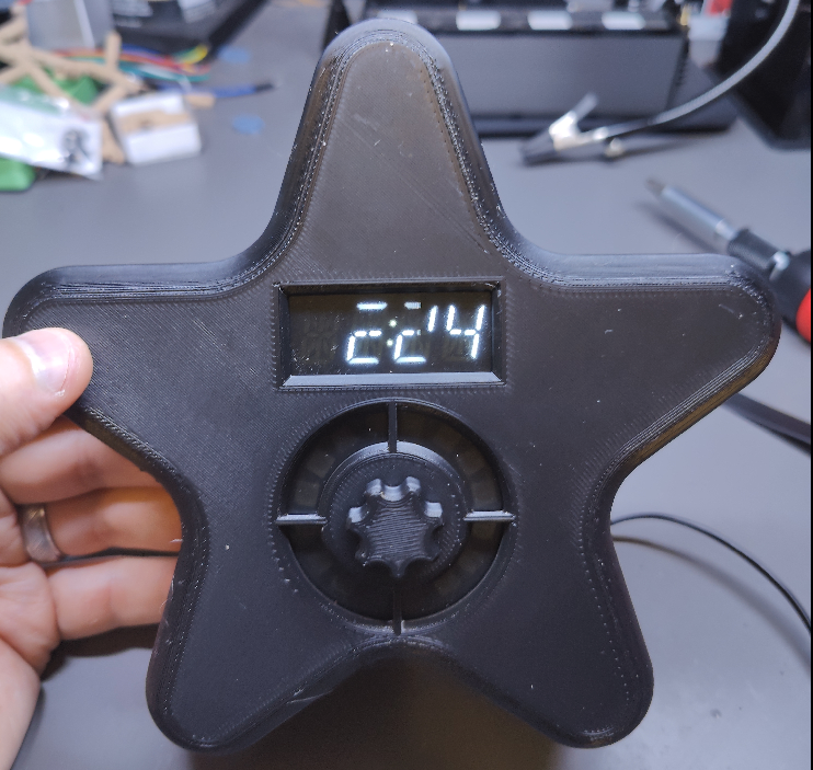
It's Alive!
![]()
My daughter has been using it for a few nights now, and loves it. She’s excited about getting to paint it soon, once I have time to disassemble it long enough to do so, and likes knowing when it’s “almost time.”
Next big step is adding the bluetooth functionality, so I can check and adjust the schedule and start/stop naps without having to go into her room to do it. But given my limited experience with mobile development I expect that to take a fair while.
-
Nap, Lock, and some new hardware
07/27/2025 at 17:58 • 0 commentsThe software has seen a few improvements since the previous project log, and there have been some hardware changes.
To start with the latter, I've switched from the ESP32 WROOM devkit I was using previously to a Seeed XIAO ESP32 S3. This was mostly to save space, once I realized I wouldn't need more pins than were already available on the XIAO. I had originally planned on switching to a Seeed XIAO ESP32 C3, before realizing the C3 doesn't have the PCNT support for the rotary encoder. Rather than switching to a software solution for the encoder, I just grabbed the S3 instead.
I have also replaced the single RGB LED with a NeoPixel Ring from Adafruit. My daughter had complained once or twice about not knowing how much longer she needed to stay in her room. The ring can be set up to light up only some of its LEDs to indicate remaining time in a visual way.
![]()
The software has seens some upgrades as well. The dial can now be used to adjust the brightness of the display and LED ring, start a nap, and lock the display. The switch has to be held for 3s to unlock it again. This is all the functionality I had intended to include for local control, at least for the MVP, so I think the software changes will slow down for a bit now. I have started work on designing a PCB in KiCad, and building PoC for it on perf-board. I've also started working on a design for the case.
![]()
The thought is that the face/control panel will be 3d printable separate from the rest of the case, and connect to the main PCB via a few JST-XH connectors. That way, different designs just have to have a sufficiently large flat surface, and some alignment pins/screw holes to attach it. The PCB will likely also just attach with some small metric bolts, so the case would also need some embedded nuts, heatset inserts, or other threaded holes for it to attach to. The panel slot will, at least on my case, I think be designed to have space for a semi-transparent acrylic sheet to act as a bit of a diffuser/dimmer layer.
![]()
I'm also experimenting a bit with removing the battery holder from the RTC module I've got, and instead connecting it to the module via some wires, so it can be placed somewhere more accessible (E.G. to have a battery cover somewhere on the case, so the battery can be swapped without completely opening it.)
-
Where I'm "Starting" From
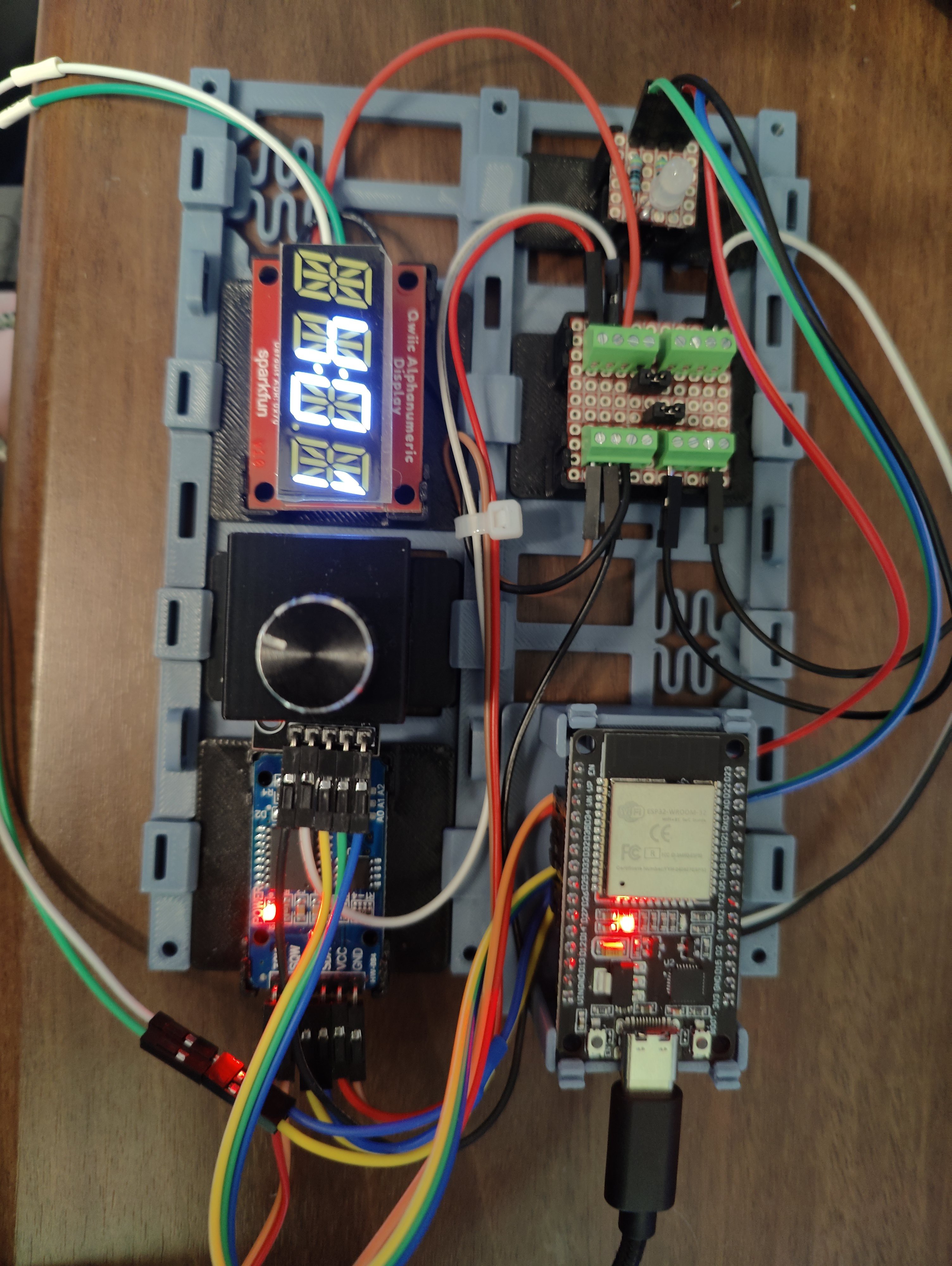
07/07/2025 at 20:24 • 0 commentsI've already got a few evenings of work in on this, and have made some decent progress. So far I have an ESP32 driving an alphanumeric display, controlled by a rotary encoder (w/ switch). The control can be used to set the time, or to program a basic schedule (start sleeping, stop sleeping). Time is kept by an RTC with a battery backup. When the current time falls within one of the time blocks in the schedule, an RGB LED lights up accordingly.
![]()
The OK-to-Wake clock we're currently using with my daughter has three blocks of time in a given schedule. A block for sleeping (red), a block for playing quietly in the morning (yellow), and an OK-to-Wake window (green). When it's not in any of these states, it turns white. When setting the schedule, all you can do is set the start/stop for the sleeping block, and toggle the (hard-coded at 15 minutes) block for playing quietly.
For my clock, I want to support four states: Wind-Down, Sleep, Quiet, and Wake, which will take place in that order each night. Setting all of that with the dial on a single 4-character alphanumeric display would be tedious at best. As such, my current plan is to keep an interface similar to the one on our existing wake clock for the dial - you just set a sleep window, and the rest is automatically configured. I also want to eventually support different schedules for each day of the week (stay up later on weekend nights, for example), but that also feels like it would be annoying to input in the device itself. Again, to "resolve" this for now, the schedule is just set for all seven days when it's set on the clock.
I have not yet gotten around to setting up the nap/override behavior, or a lock function (the chance of the 2y/o not fiddling with it is basically zero), so those are next on my list. Once all that basic functionality is in place, I intend to shift focus to the wireless control. I want to put together a simple app which can connect to the device over bluetooth. I'm going with bluetooth instead of wifi because I want to be able to take it with us on vacations, where I can't guarantee I'd be able to connect it to wifi.
The app will, hopefully, be able to set the schedule more granularly; manual control of each time block, on a per-day-of-the-week basis. I'm also hoping to allow it to set overrides for the current day. This would be used to set up nap periods, or to adjust the schedule for one night only.
Finally, once the app is functional and everything is working, I want to look into a 3D-printed enclosure for it all. I have no idea yet what shape it will take, that'll likely be up to my daughter, but ideally that will be the most flexible part. I'd love it if other folks could pick up this project, and design different enclosures for their kids. As part of that, I may also look into designing a custom PCB, but definitely not set on that yet.
DIY OK-to-Wake Clock
A DIY alternative to commercially available OK-to-Wake clocks for sleep training toddlers.