Close
0%
0%

IR power switch for NucBox G5

Add IR power switch to a mini PC to turn on it with TV remote.

Similar projects worth following
410 views
0 followers
I am going to use this tiny PC to watch netflix on my living room.
So it would be handy if I am able to power on the PC with a TV remote.
This project aims to achieve it without compromising compactness of the PC.

In mini PCs, power switch is soldered to a board directly and I need custom solution.

What I need to do is simple:

  1. Find out which pin is the pin to turn on and attach a cable to it to connect to a mcu.
  2. Find out what can be used to power mcu.
  3. Connect IR receiver to mcu.
  4. Program mcu to output low to power switch pin when it received particular remote control signal.
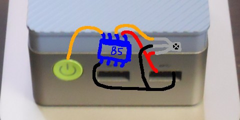
Another option is to use Wake on Lan, but it would require a larger device.

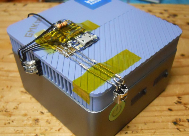
Anyway, to attach a cable to power switch pins, I created a custom connector and forcibly insert it into the gap between PCB and fan platform. See project log "Created connector" for the detail.

It finally looks like below photo. At first I was thinking to place everything inside top cover, but I took easy route.
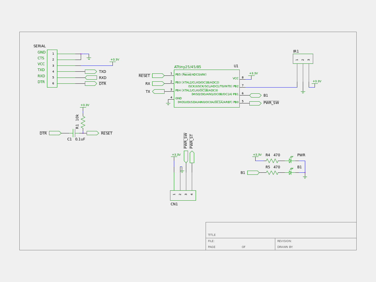
irswitch-sch.pdf

circuit diagram

Adobe Portable Document Format - 10.27 kB - 04/06/2026 at 12:19

Preview

  • 1 × NucBox G5
  • 1 × IR receiver module
  • 1 × ATtiny85 module (Adafruit trinket)
  • 1 × tactile switch
  • 1 × 1.27mm pitch Universal prototype board

View all 6 components

  • Changed to USB

    teru • 04/06/2026 at 11:04 • 0 comments

    After changing power source to USB, it worked.

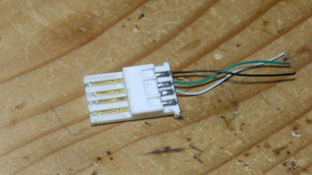
    I used junk USB plug which sit in parts box for years.

  • Built up

    teru • 03/29/2026 at 11:54 • 0 comments

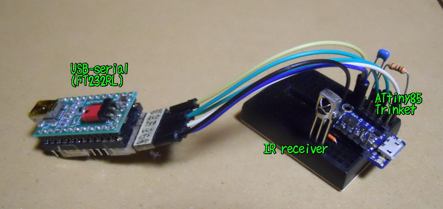
    I wired up the attiny85 and the IR receiver.
    Now it's time to power on the PC with a TV remote!

    And of course it does not work...

    This is because the Vcc voltage was too low. When I measured it, it was about 1.9V.
    Perhaps I should have tested if the power pin was actualy usable before building up it.

  • Created connector

    teru • 03/21/2026 at 09:16 • 0 comments

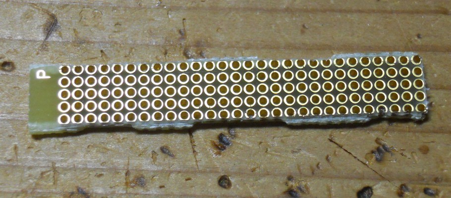
    I made a connector using a universal prototype board with a 1.27mm pitch. I checked quickly and confirmed it is making contact with the switch pins.

    Connector connected to the switch
    The front side of the connector
    The back side of the connector, where it makes contact with the switch pins.
    1.27mm pitch Universal prototype board

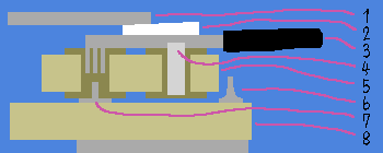
    The following cross-sectional diagram shows how I attempted to connect the wires to the switch.
    I wrapped the connector in polyimide tape to prevent it from short-circuiting with the switch case's feet.

    1. Platform of the cpu fan
    2. Wedge to secure the connector
    3. Cable
    4. Solder to attach wire to universal prototype board
    5. Universal prototype board
    6. Leg of the power switch's case
    7. Pin of the power switch
    8. Mother board of the PC

  • Add learning mode

    teru • 08/03/2025 at 06:36 • 0 comments

    Added code learning mode so power on code can be changed without uploading firmware.

    Add push switch between IR pin and ground, and hold it down while reset, then device enters learning mode.

    In this learning mode, device accepts IR signal twice. If the 2 signals are same, it is saved to eeprom and will be used as power on code.

  • IR library works

    teru • 07/29/2025 at 12:31 • 0 comments

    After some push and pulls, I mostly understand the IR library and now it recognize TV remote signals.

    It blinks red LED upon receiving specific IR signal.

  • Development on a breadboard

    teru • 07/23/2025 at 12:30 • 0 comments

    I set up development environment on a breadboard.

    I'm trying to make IR library work with ATtiny85. IR library is this one by ChaN.

  • Circuit diagram

    teru • 07/18/2025 at 12:13 • 0 comments

    For a mcu, I am planning to use ATtiny85, specifically Adafruit's trinket.

    Althogh the device has USB connector, I don't remember how to use it. I ignored the USB and flashed optiboot and using serial to communicate to the device.

  • Find out pin assignments of the power switch

    teru • 07/15/2025 at 12:04 • 0 comments

    First of all, I need to know which pins should I short to turn on the PC.

    I opened case and checked pin assignments by measuring voltage and resistance.
    Result is in the following picture:

    First pin, left most one, outputs 3.3V even if system is shut down. This seems to powering LED.
    Second pin is connected to ground.
    Third is the one I need. Shorting it to ground turns on the PC.
    Forth pin controls the LED. Shorting it to ground turns on the LED.
    In the other words, outer pins are for LED, inner pins are for switch.

    It turned out there is everything I need: power, ground and switch. Additionaly, I may be able to use LED control pin to detect whether PC is on or off.
    I don't know how much power I can draw from the 3.3V source, but it is unlikely to hurt anything if I draw a few milliamperes.

View all 8 project logs

Enjoy this project?

Share

Discussions

Similar Projects

Does this project spark your interest?

Become a member to follow this project and never miss any updates