teru
teru-
Add learning mode
08/03/2025 at 06:36 • 0 commentsAdded code learning mode so power on code can be changed without uploading firmware.
Add push switch between IR pin and ground, and hold it down while reset, then device enters learning mode.
In this learning mode, device accepts IR signal twice. If the 2 signals are same, it is saved to eeprom and will be used as power on code.
![]()
![]()
-
IR library works
07/29/2025 at 12:31 • 0 commentsAfter some push and pulls, I mostly understand the IR library and now it recognize TV remote signals.
It blinks red LED upon receiving specific IR signal.
-
Development on a breadboard
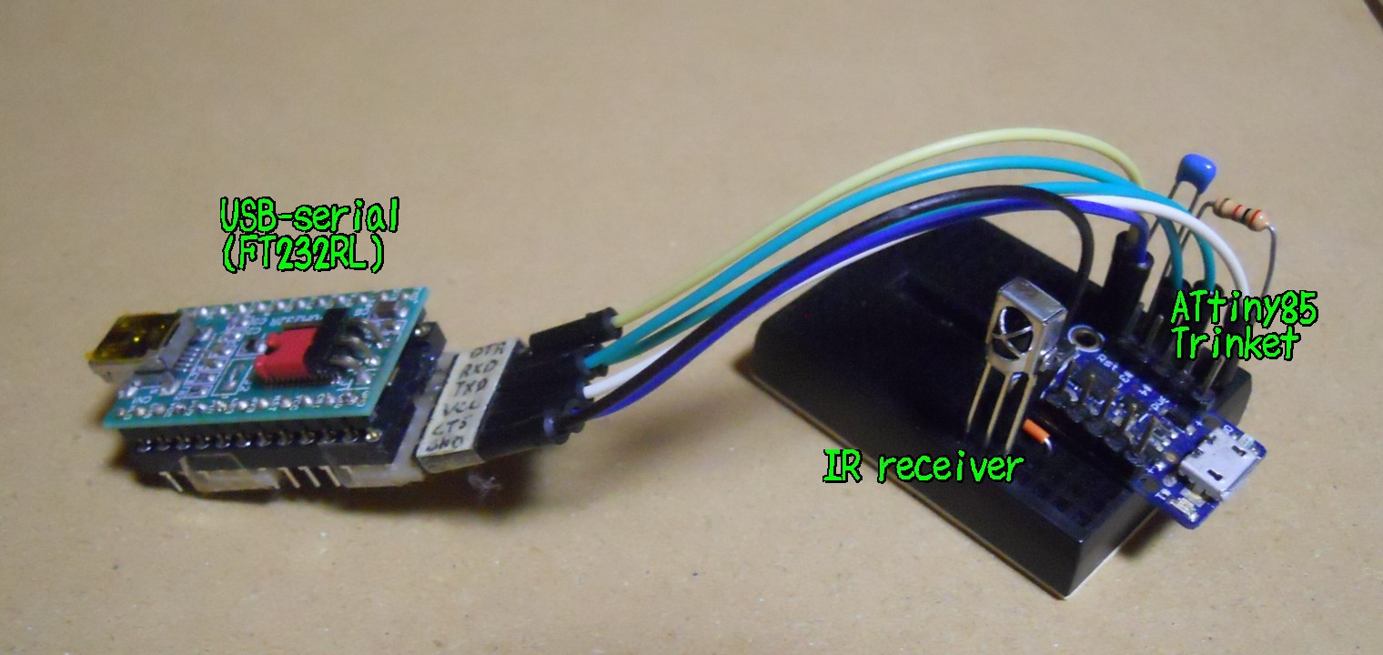
07/23/2025 at 12:30 • 0 commentsI set up development environment on a breadboard.
![]()
I'm trying to make IR library work with ATtiny85. IR library is this one by ChaN.
-
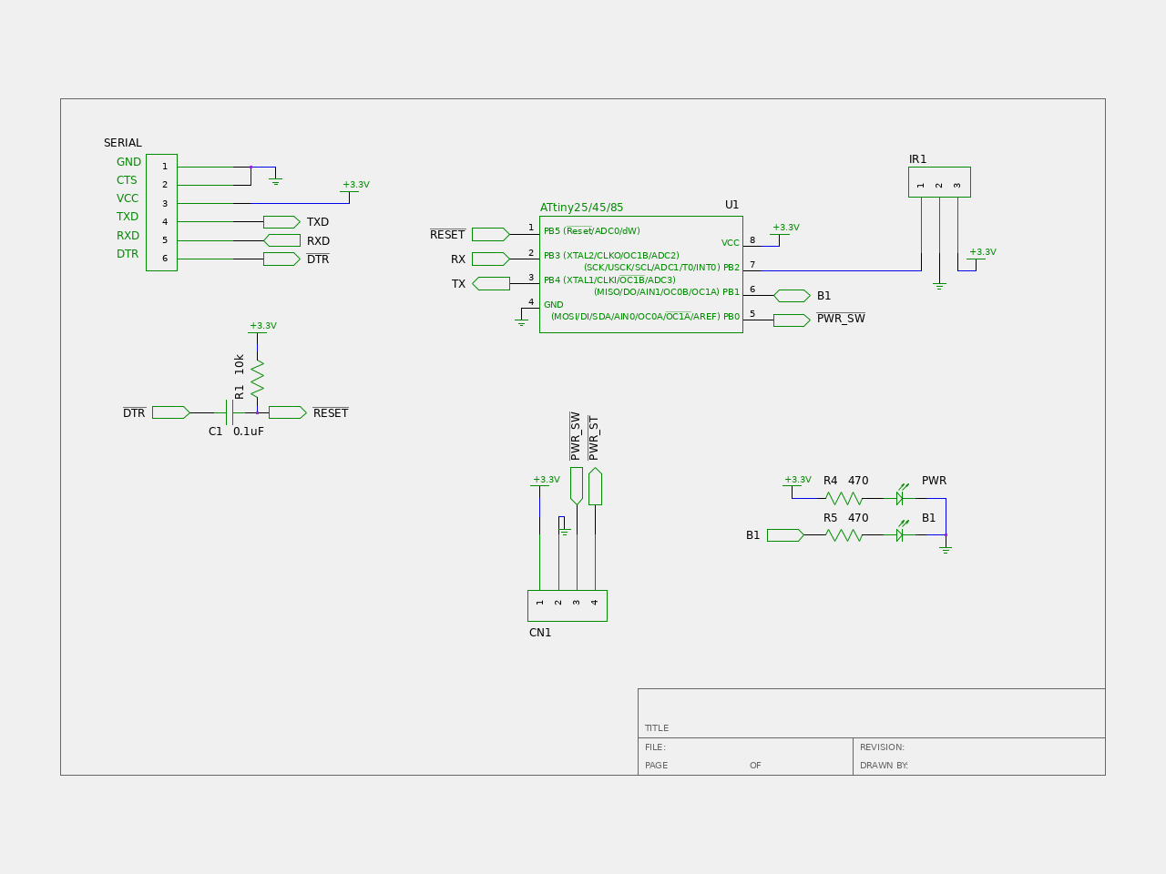
Circuit diagram
07/18/2025 at 12:13 • 0 commentsFor a mcu, I am planning to use ATtiny85, specifically Adafruit's trinket.
![]()
Althogh the device has USB connector, I don't remember how to use it. I ignored the USB and flashed optiboot and using serial to communicate to the device.
-
Find out pin assignments of the power switch
07/15/2025 at 12:04 • 0 commentsFirst of all, I need to know which pins should I short to turn on the PC.
I opened case and checked pin assignments by measuring voltage and resistance.
Result is in the following picture:![]()
First pin, left most one, outputs 3.3V even if system is shut down. This seems to powering LED.
Second pin is connected to ground.
Third is the one I need. Shorting it to ground turns on the PC.
Forth pin controls the LED. Shorting it to ground turns on the LED.
In the other words, outer pins are for LED, inner pins are for switch.It turned out there is everything I need: power, ground and switch. Additionaly, I may be able to use LED control pin to detect whether PC is on or off.
I don't know how much power I can draw from the 3.3V source, but it is unlikely to hurt anything if I draw a few milliamperes.
IR power switch for NucBox G5
Add IR power switch to a mini PC to turn on it with TV remote.