 Pierre-Loup M.
A few weeks ago, I was reading the RP2040 datasheet to learn about the clocks and how to use them, when I came across the integrated ring oscillator. Intrigued as I was, I've looked around the Internet to learn more about ring oscillators, rapidly gaining a basic understanding of them.
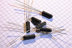
Then I wondered if one could be made with discrete components I had lying aorund, and if it could be slowed down enough to show seconds.
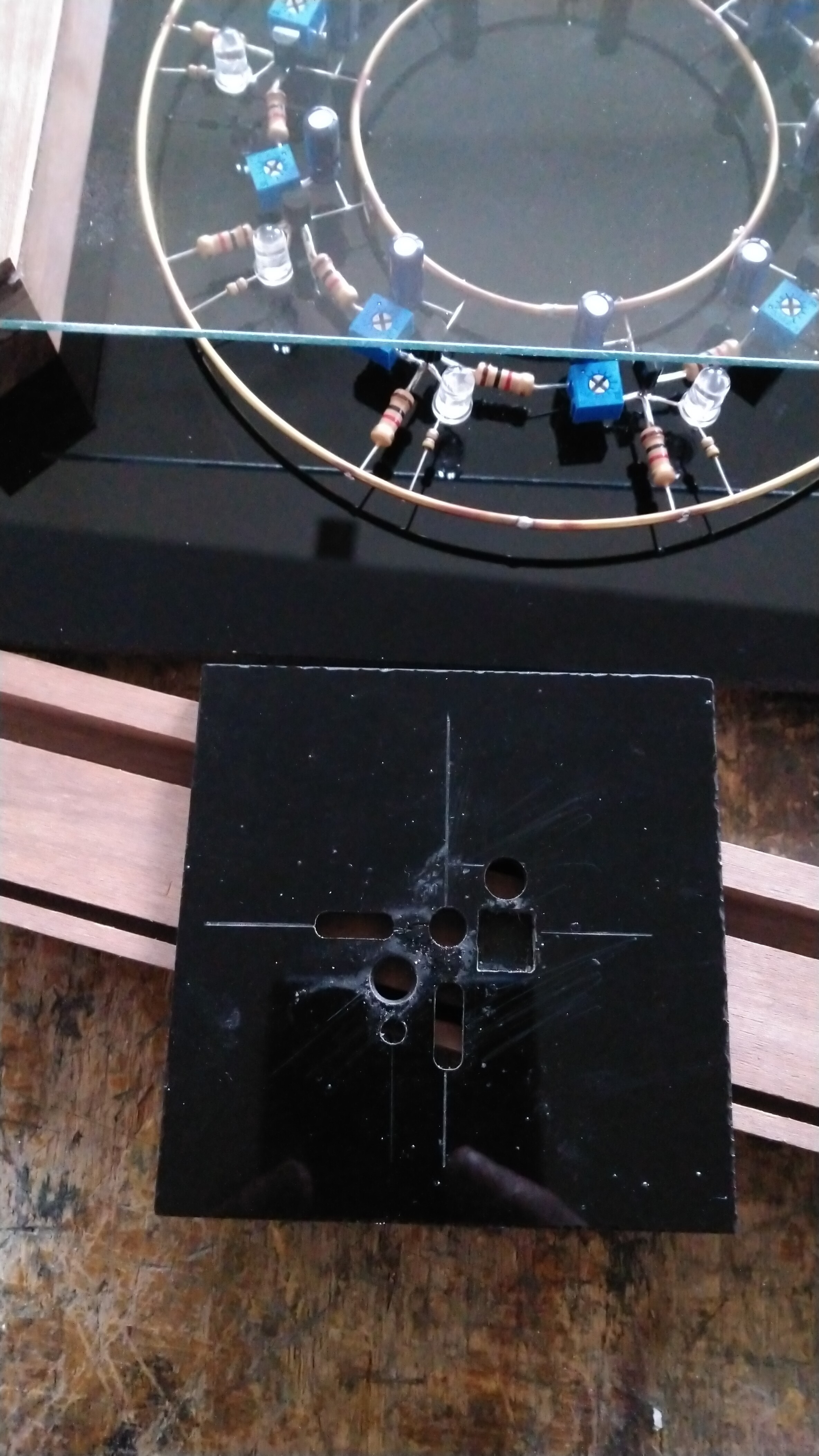
This sculpture is an attempt to do so. The size is 180x180x37mm.
Please read the logs entry to learn more about it !
Logs :
1 - What's a ring oscillator ?
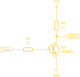
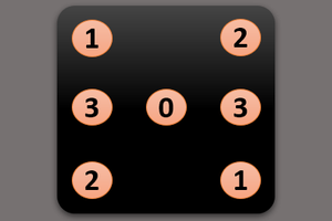
2 - Creating a NOT gate
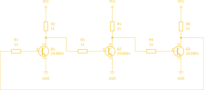
3 - Creating a ring oscillator
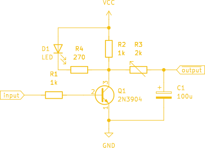
4 - Slowing down the propagation delay
5 - Visual feedback
6 - Putting everything together
Disclaimer : I usually create electronic circuits around microcontrollers, and am mainly a programmer. Be kind enough to excuse trivial errors or approximation I've made on this simple circuit, as well as imprecisions you may note. If you know how to explain things simply and without being condescendant, I'll be happy to read from you. :)


 Yann Guidon / YGDES
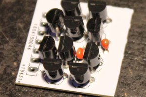
 Tim
Tim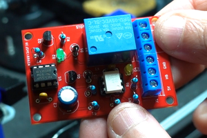
 Sergio Ghirardelli
IMHO, this ought to be a winner. Why? Yes, it's fun and cool looking. But what puts it over the top is a writeup that's designed to educate the reader. For me, education is what this site is (or should be) all about. Showing off cool projects may get brief attention, but educating readers does something of much greater and lasting value. Great job!