 Edward
Most of the effort in a test isn’t running the test—it’s getting everything to work together.
Wiring signals, configuring controllers, coordinating equipment, and setting up data logging can take longer than the test itself.
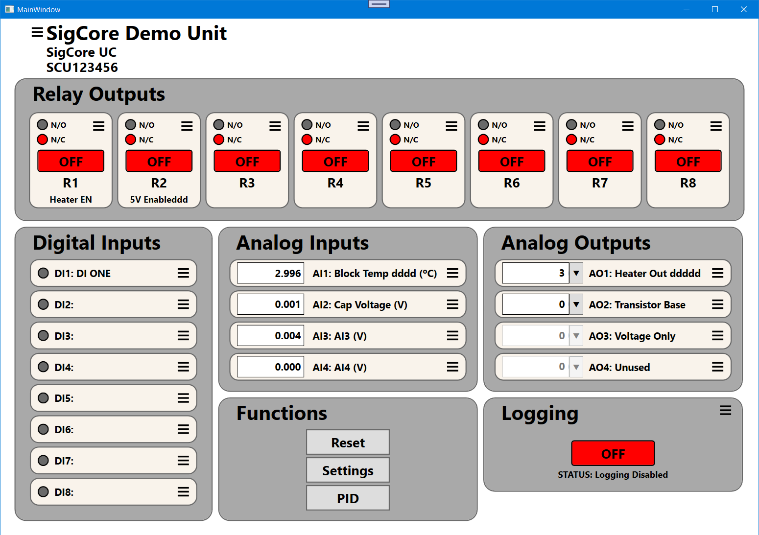
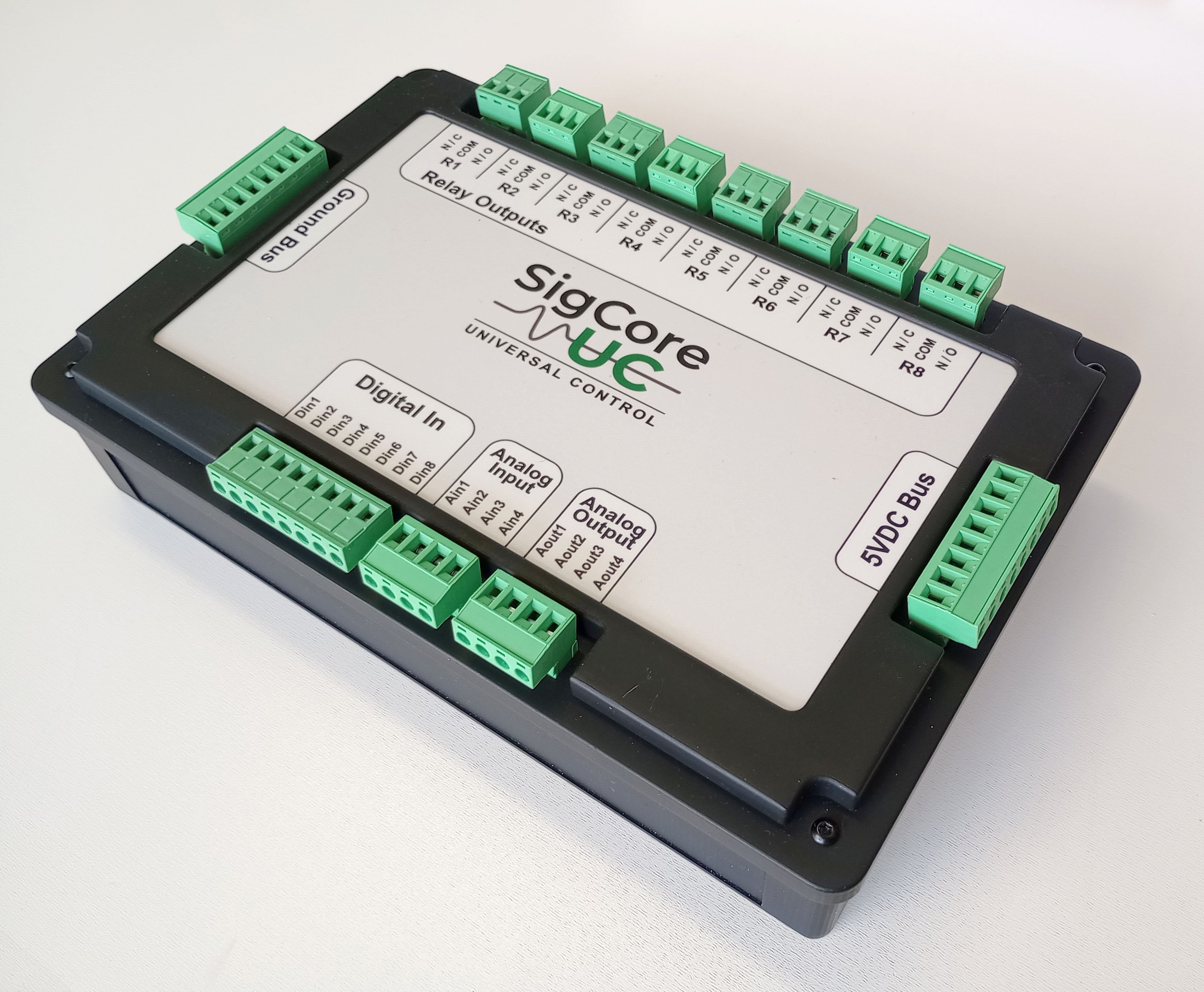
SigCore UC is a control system built specifically for test setups.
It lets engineers connect equipment, run tests, and log data—without building a full control stack every time.
Instead of piecing together controllers, scripts, and logging tools, everything is handled in one system so you can focus on the test, not the infrastructure.
Follow the project on Crowd Supply for launch updates.
 Jithin
 smartroad
 Tijl Schepens