 scott
scottProject Phases & Goals
- Mechanical Design
- Camera Assembly [COMPLETE]
- Gimbal Assembly
- PCB Cover
- Stand
- Electrical Design
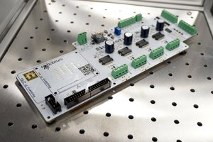
- Motor driver PCB [COMPLETE]
- Endstop switches [COMPLETE]
- Motor connections [COMPLETE]
- Software Design
- MCU (Motor driver PCB)
- Endstop interrupts [COMPLETE]
- Motor driving functions [COMPLETE]
- Laser function [COMPLETE]
- UART Tx and Rx
- Pi 5
- UART Tx and Rx
- OpenCV camera functionality
- Distance calculation
- 3D images
- MCU (Motor driver PCB)
References, Other works
DSLR Camera Slider (Stepper Motor Driven)
https://www.thingiverse.com/thing:4512714
Created by isaac879, July 1st, 2020
Creative Commons - Attribution - Non-Commercial
28BYJ-48 Stepper Motor
https://grabcad.com/library/28byj-48-stepper-motor-7
Created by Automated Neurotic, Jan 7th, 2024
GrabCAD
Raspberry Pi HQ Camera
https://grabcad.com/library/raspberry-pi-hq-camera-1
Created by Yarsh Turkar, May 1st, 2020
GrabCAD
Limit switch SPDT sim roller
https://grabcad.com/library/limit-switch-spdt-sim-roller-1
Created by Damien Sorel, January 7th, 2024
GrabCAD
NEMA 17 Stepper Motor 23mm
https://grabcad.com/library/nema-17-stepper-motor-23mm-1/details?folder_id=14122235
Created by Jorge Omar , Ferreyra Libano, May 10th, 2025
GrabCAD
A4988 Stepper Driver - With Pins & Socketed
https://grabcad.com/library/a4988-stepper-driver-with-pins-socketed-1
Created by Scott Mudge, August 15th, 2023
GrabCAD
 David Held
 Nancy Yi Liang
 roboteurs