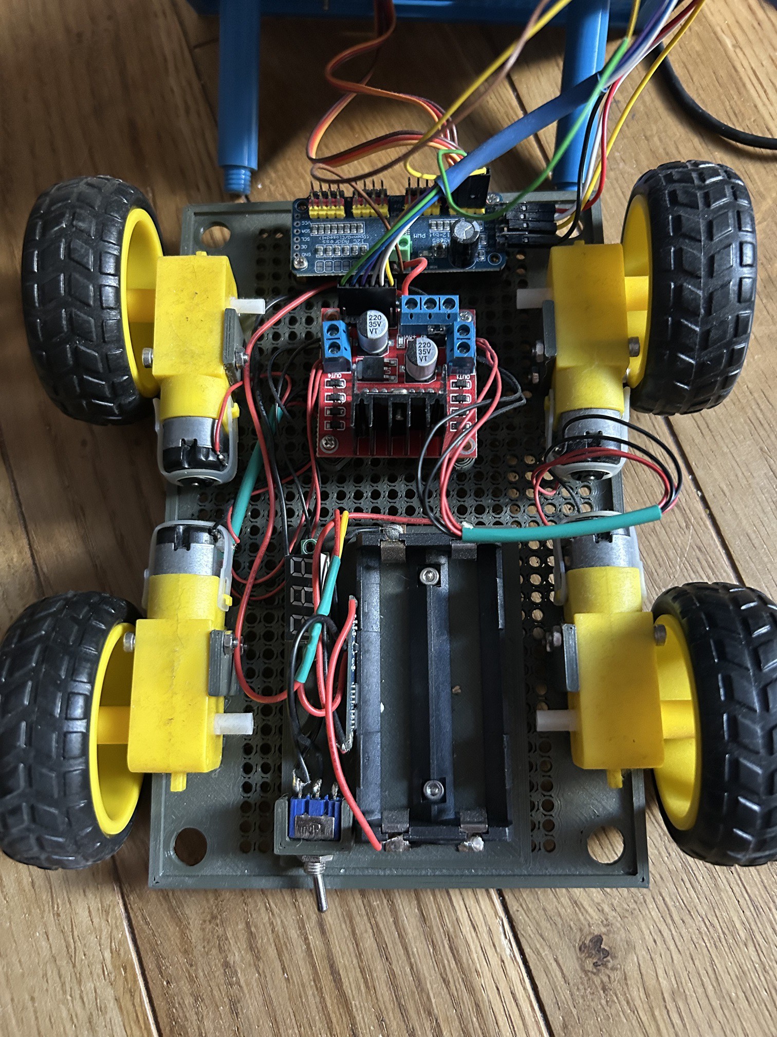
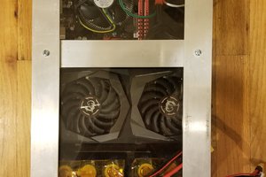
The latest itteration of the car inculdes:
- Raspi Zero 2 as central component,
- Astro PI shield for some extra sensors and the LED Matrix
- I2C controler for the servos
- L298N H Bridge as motor controler
- some Grove I2C components
- 2 Custom build 18650 based battery packs
0%
0%
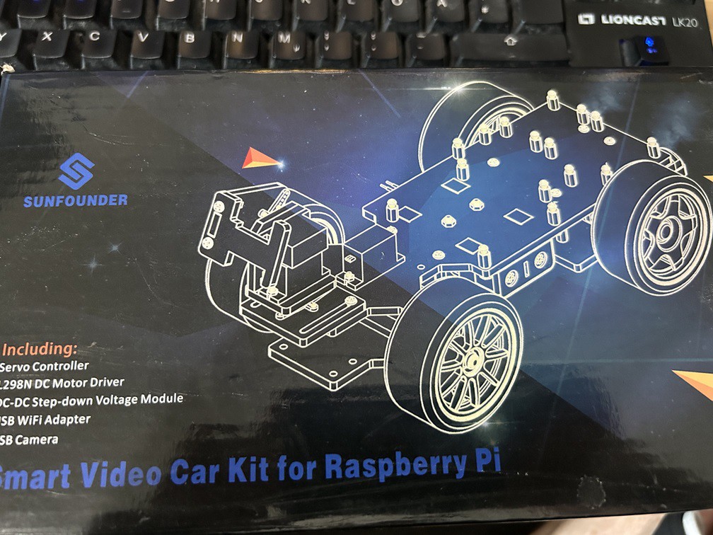
The modular learning car project
There are tons of arduino or raspi car kits out there but they are not very flexible. With this I want to share my learning journey
Become a Hackaday.io member
Already have an account? Log in.
Just one more thing
To make the experience fit your profile, pick a username and tell us what interests you.
Pick an awesome username
hackaday.io/
Your profile's URL: hackaday.io/username. Max 25 alphanumeric characters.
Pick a few interests
Projects that share your interests
People that share your interests


 ServError
 Bob Baddeley
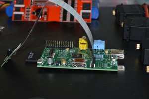
 8bithalfadder
 MCenderdragon