-
Drive control - the state of the machine with a state machine
08/30/2025 at 11:30 • 0 commentsFinally found some time to continue.
I added 3 instructions on my take to control the motors.
My goal was not just simply control the motors. My aim was also to improve a bit on my python skills and make the setup as modular as possible.In this steps you will learn about my take on:
- wiring up the components
- a python class to run the L298N
- a state machine to make the drive control more robust and understandable
![]()
And as always - feedback and critics is always welcome -
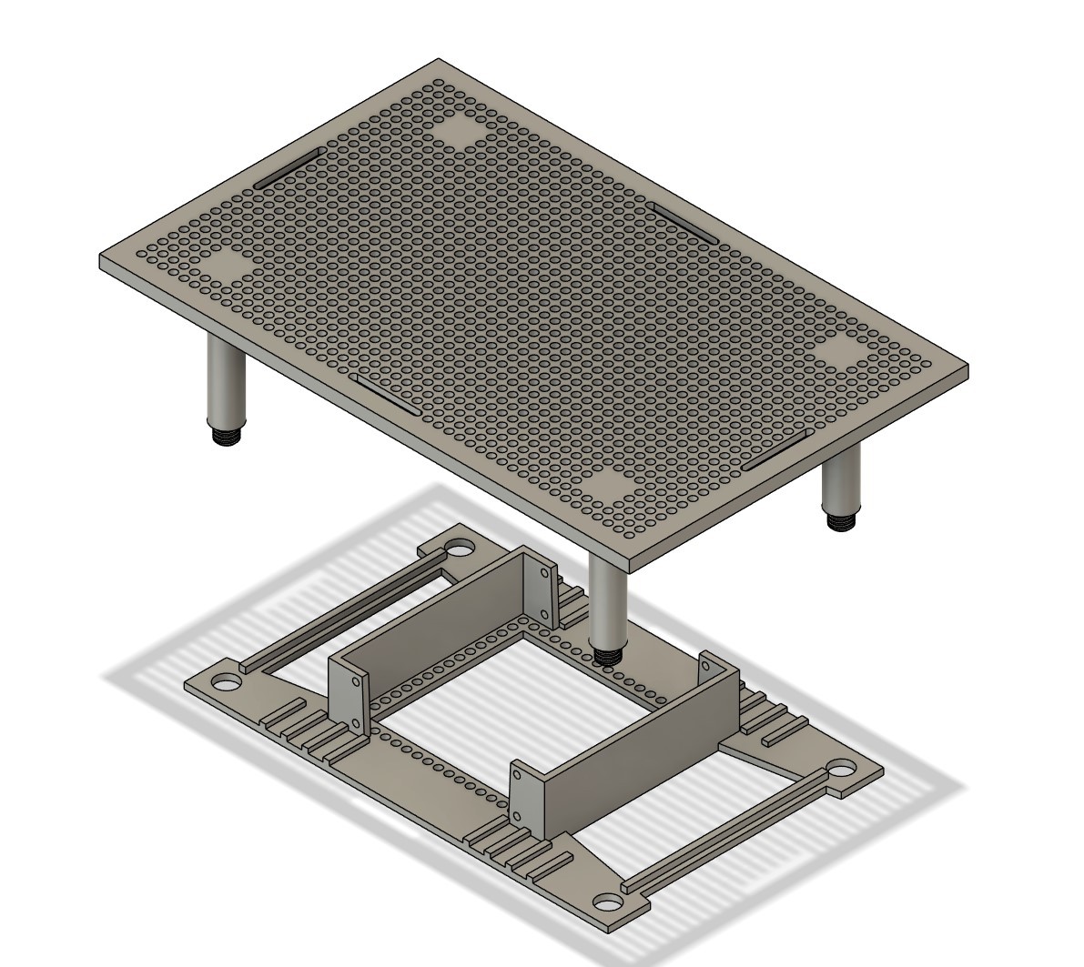
Build your own carrier
08/15/2025 at 14:17 • 0 commentsThe idea of the modular car is that you can just add pretty much any component on a breakout without much effort. No matter if you want to run on an arduino or a Raspi 5 it is easy. I added an instruction how you can build your own carrier for the grid
![]()
-
Power up without burning your house down
08/14/2025 at 20:54 • 0 commentsFirst of all we need power for our car. I assume you have a basic understanding about Volts, Amperes, short circuits and such things ;o)
There are different options how to power your learning car. What you need as battery is up to a couple of factors. The most important one is what kind of components you want to use.
- Different boards require different voltage to work.
Some Arduinos want 3,3 Volts while a Raspberry PI want's 5 or 5,1 Volts . Depending on the load you put on the board the power consumption may also vary. E.G if you drive some Neopixel LEDs over the GPIO pins this power is drawn from the boards power supply. Power consumption is measured in Watt.
Watt = Volt x Ampere. So Ampere is the 2nd common thing you have to take an eye on. To stay with a Raspi 5 Volts and 2-3 Amperes are what you need. - Motors draw quite some power
No matter if it is a servo or a DC motor both are quite power hungry. Consider not to drive them over your central board. Better supply them directly from your power source/DC converter.
Another factor is simply what do you have at hand.
- AA batteries are quite common so if you but enough of them in series to stack up the volts you can use them
- Maybe you are vapping so it is pretty likely you have some 18650s lying around
- Or you have a battery pack from a RC car with a LiPO powering it
All good as long as you pay attention to the specs - Volts and Amps are key
Last but not least endurance is a factor. Endurance is power used over time. So the common units for this it Watt/hours or Amp/hours. For 18650s it is usally given as mA/h e.g. 2000 mA/h. So what does it mean. Simpy said. If your setup draws 500 milli amps a 2000 mA/h battery can sustain the setup for approximately 4 hours.
The kit I bought required 2 18650 cells so I went with those.
Voltage is 3,7 Volts - 2 in series (2S) will provide 7,4 Volts which you can step down to e.g. 5 Volts for a Raspi. And they can provide a pretty high peak voltage. I mean really high. I short circuited 2 of them in my initial battery box and the wires immediately started to glow. There are some stories they will explode on short circuits but there are some test video in the net that show that they will not blow up immediately but the get really hot - really fast.So I thought - well this is not soooo safe if you are not careful. So I learned you either can buy the 18650 as a protected variant. But they are more expensive and a bit longer so they will not fit in most battery boxes. Another option is to to build in a battery management system BMS in your setup. BMS are available on breakout boards. A BMS breakout for the 2 batteries costs around 2-3 bugs. So definitely worth it. Add an adjustable stepdown converter and you are all set.
A little story about my first BMS tests. I bought a pack of 5 wired the first up - not working. 2nd one - same not working. So I ended up with all 5 not working. I searched the net and found a guy that had the same experience with a pack of 20. So I thought that cannot be that they are all so bad. After searching a bit I learned that most of them use MOSFETs to protect I think for short circuits. MOSFETs need to be activated to work and when you disconnect them from the power source you need to reactivated them again. Common way to activate a BMS is to connect a charger. But there seems to be a little hack. I cannot explain how it exactly works but if you short the negative input and negative output of the BMS this will activate it as well. So I added a switch that will exactly do that after i switch batterysYou can find my setup in the instructions.
![]()
- Different boards require different voltage to work.
-
The beginning
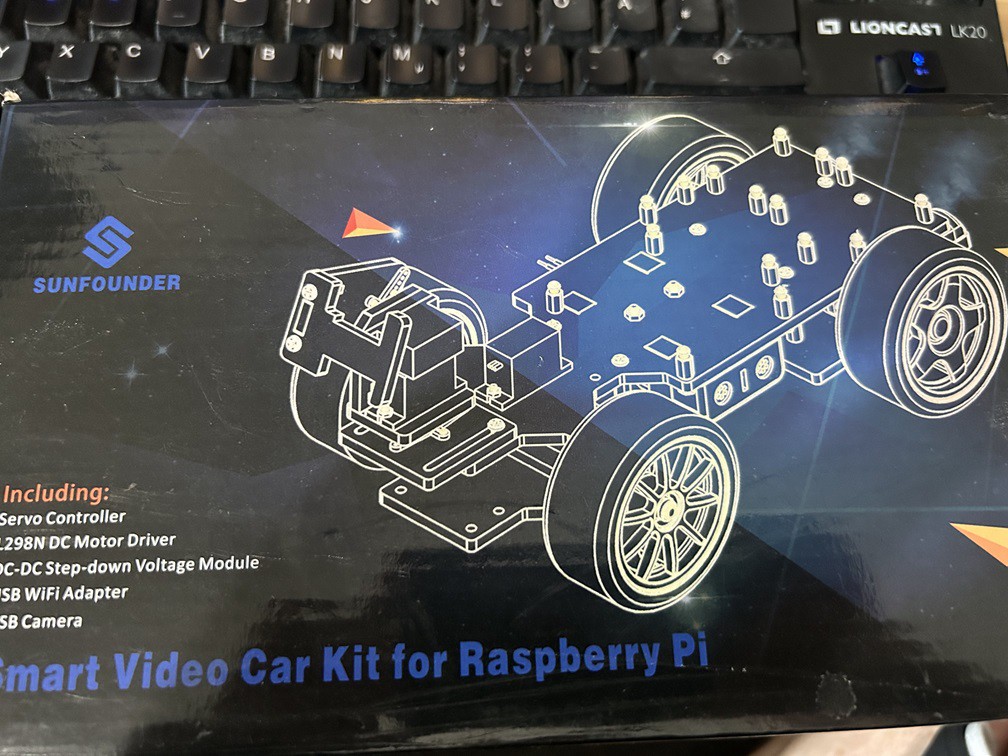
08/14/2025 at 15:58 • 0 commentsThe journey started a couple of years ago. I was not yet into open source electronics and 3d printing but I always liked to play around and when learning some stuff by doing so - even better.
I started with a kit you can buy for a couple of bugs. In my case I randomly picked this one:
![]()
The kit included some components, some laser cut parts and had space for a Raspi 2 (back in a day... ;) ).
Assembly was straight forward. Wiring up not too demanding. Download some python code and it basically worked - if you used it out of a python shell and streamd the cam on a separate browser window.
But as soon as I wanted to add another sensor - I either had to drill a hole in the precut frame or just abandon the kit.
When I got my now old 3d printer I started printing a similar frame - with predefined points to add the new parts - which was ok but really as unflexible as before.
After some tinkering around with the printer and learning some CAD I came up with the idea to build myself a prototype carrier that should be modular and reusable.
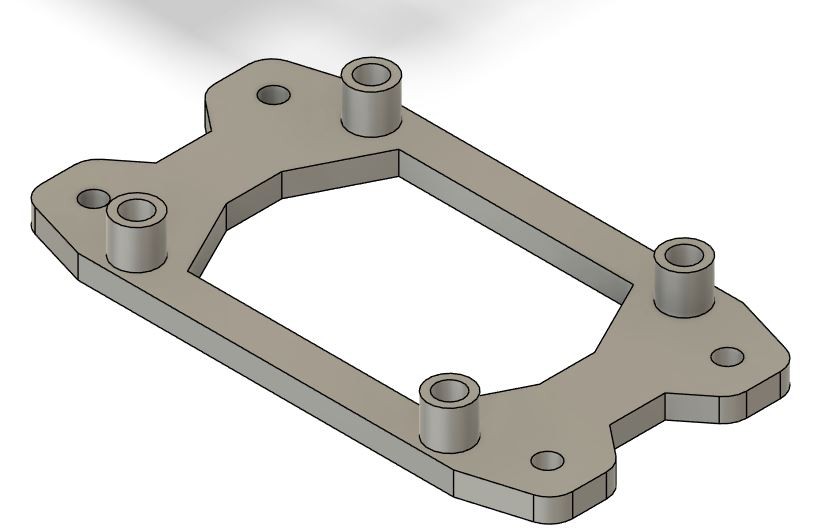
Behold - the first design version of my modular carrier frame:
![]()
The idea is pretty straight forward. Have a predefined grid of holes (5 mm center point distance) and build little carriers to house the electronic components with some spacers on it and screw them to the grid with M3 bolts.
As an example a Grove I2C Hub on its carrier.![]()
So the stage was set - to do some prototyping
The modular learning car project
There are tons of arduino or raspi car kits out there but they are not very flexible. With this I want to share my learning journey