-
1How to create your own carrier
In this instruction I will show you how to construct a simple carrier for any part you want to add on the grid. I will show case it in Fusion 360 but you can use any CAD you fancy. The approach should be the same.
The board I want to add is a Raspi Zero 2 W. The easiest way to start is to find a drawing with the dimensions on it. For the Zero 2 this is pretty easy:
Zero 2 Mechanical drawingWe are interested in the bores for mounting e.g. on spacers
![]()
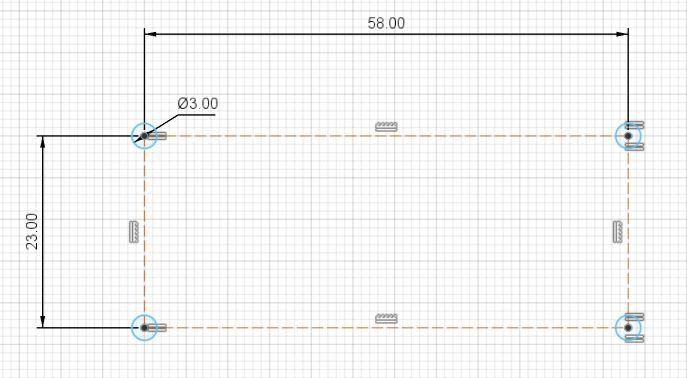
The 4 centers of the bore are on a rectangle with the dimension 23 mm x 58 mm.
Note: The dimension for on of the straight is measured over the symmetry line so it is 2 times 29 millSo we can start with this rectangle as a construction line helper in a new sketch.
![]()
The diameter of the spacer is usually 2,5 mm so I will go with 3 mm to add some tolerance. Add all 4 of them on the corners of the construction rectangle. I like to constraint only one circle and add an equal constraint to the other 3 in case I want to change the bore diameter
![]()
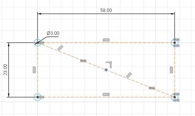
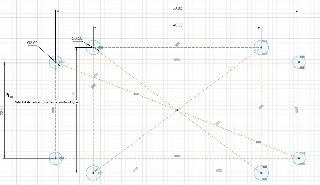
The next step is to prepare the bores for the grid. I use M3 bolts for it so I go with 3,5mm diameter circles to add some tolerance again. The carrier grid is 5 mm between the center points of every hole. So any distance that divides by 5 evenly is good. Where you put the carrier mounts is up to your preference. I will go with a 30 mm x 40 mm for now. Using a center point rectangle for symmetry. Since I did not do a center point for the previous rectangle. It can be added pretty quickly by adding to line from one corner to the opposite one. Add parallel and equal constraint on the straight and you end up with the center point. Like this
![]()
![]()
![]()
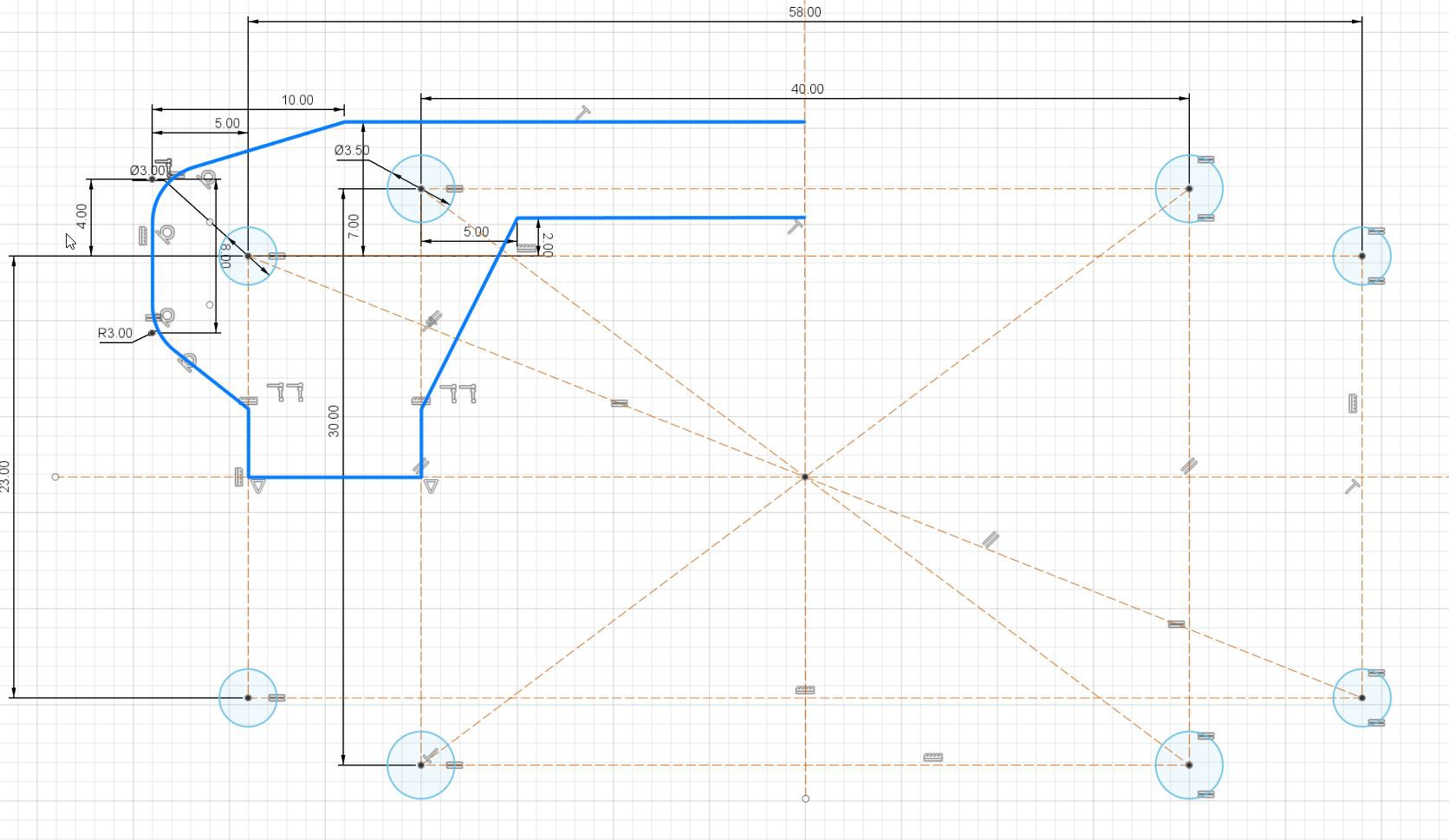
The next step is to shape the carrier itself -I will add a horizontal symmetry construction line where I will mirror the half later one. Here as well shape it however you like
I ended up with something like this - maybe not the most efficient way to do it - but hey if it is stupid but it works - it is not stupid ;)
![]()
and after mirroring
![]()
Next is to extrude. I usually go with 3 mill
![]()
Last step is to add some spacers so the carrier will be above the gird. This is required so you can fix e.g. the nuts of the brass spacers - like this
![]()
So you already know the drill - add some more circles in a new sketch - I go with 5.5 mm and of course concentric to the bore
![]()
Extrude it 5 mm
![]()
Ready to export it to your slicer of choice and 3d print it
Happy tinkering!
-
2Custom 18650 battery pack with adjustable output volltage
![]()
If you want to use my design you can use the STL files over at: Modular learning car project by Benksterini | Download free STL model | Printables.com
Warning:
- Be careful with the 18650 cells - they pack a punch
- Maybe obvious BUT DO NOT solder on the PLA carrier!!! ;o)Parts used:
1 - 18650 batteries on a battery box
2 - Voltmeter (blue digits) output voltage from buck converter
3 - Voltmeter (orange digits) input voltage from battery box
4 - Battery Management System (HX 2S 10A)
5 - SPDT switch
6 - Mini buck converter
7 - clamps to attach e.g. a USB cableWire it up like this
![]()
The SPDT switch is a little hack to activate the MOSFETs on the BMS without putting it on a charger after the 18650 are changed.
-> Switch for normal operations - orange to black wire.
-> Switch to activate after battery change - orange to orange
Happy tinkering! -
3Drive setup - wire up the motors
The current car I run has a dedicated motor for each of the wheels. Driving works like with a tracked vehicle - turning just means that the motors on the one side will slow down or stop.
The components I used are documented pretty well on the net - so there is no need here to go into the details. If you are interested in the details just search the net for the component. I will stick with the basics for understanding here only- L298N Motor driver
The motors are driven by a L298N motor driver.
Important for the setup to understand:
- Power supply (Input)
The power input can range between 5 - 12 Volts ( some sources state up to 45 Volts). - Power supply (Output)
The board has a 5 Volt output that can handle up to 2 AMPs - Direction control
The 2 motor outputs/directions are controlled by 4 digital PINs - Motor speed
Simply said DC motor speed is depending on the voltage the motors are running on. The L298N uses Pulse Wide Modulation (PWM) to control the output
voltage for the motors.
- PCA9685 servo controller
The PCA9658 is a 16 bit 12 channel PWM Servo driver that is accessed over I2C bus.
While a lot of boards like the Raspberry PI Zero 2 W have PWM pins on board some sources state the PWM output quality is better on the PCA9658. Having it on the car anyways to control the servos for the cam holder - I use it to control the speed of the motors.
Important for the setup to understand:- Power supply
The PCA9685 has 2 power inputs. One to supply the logic circuit and another one to supply the attached servo motors. Both are 5 Volts for the boards I use. - Controller access
The board is managed over I2C - PWM
Since the motor driver has its own power supply only the PWM pins on the output channels are used.
- Power supply
- DC Motors
In my setup the DC motors are in tandem but they are in different directions on one side. Since the direction of the motor depends on where the positive and negative input is - cross wiring the motors on every side is a simple solution to this. - Power Supply
I decided to go with a separate power supply for the Controller (Raspberry PI) and the Motors - Raspberry PI Zero 2 requires a 5.1 Volt power input over USB connector
I used the custom 18650 power pack explained earlier for this - The motors have its one 18650 power pack. Since the L298N has an onboard voltage converter there is no need for the step down converter on the power pack for the motors, But I would strongly recommend a battery management system for the motors as well
- IMPORTANT: To avoid signal interferences you have to have a common ground for the setup
In my setup I bridge the motor power supply ground with a ground pin of the Raspi
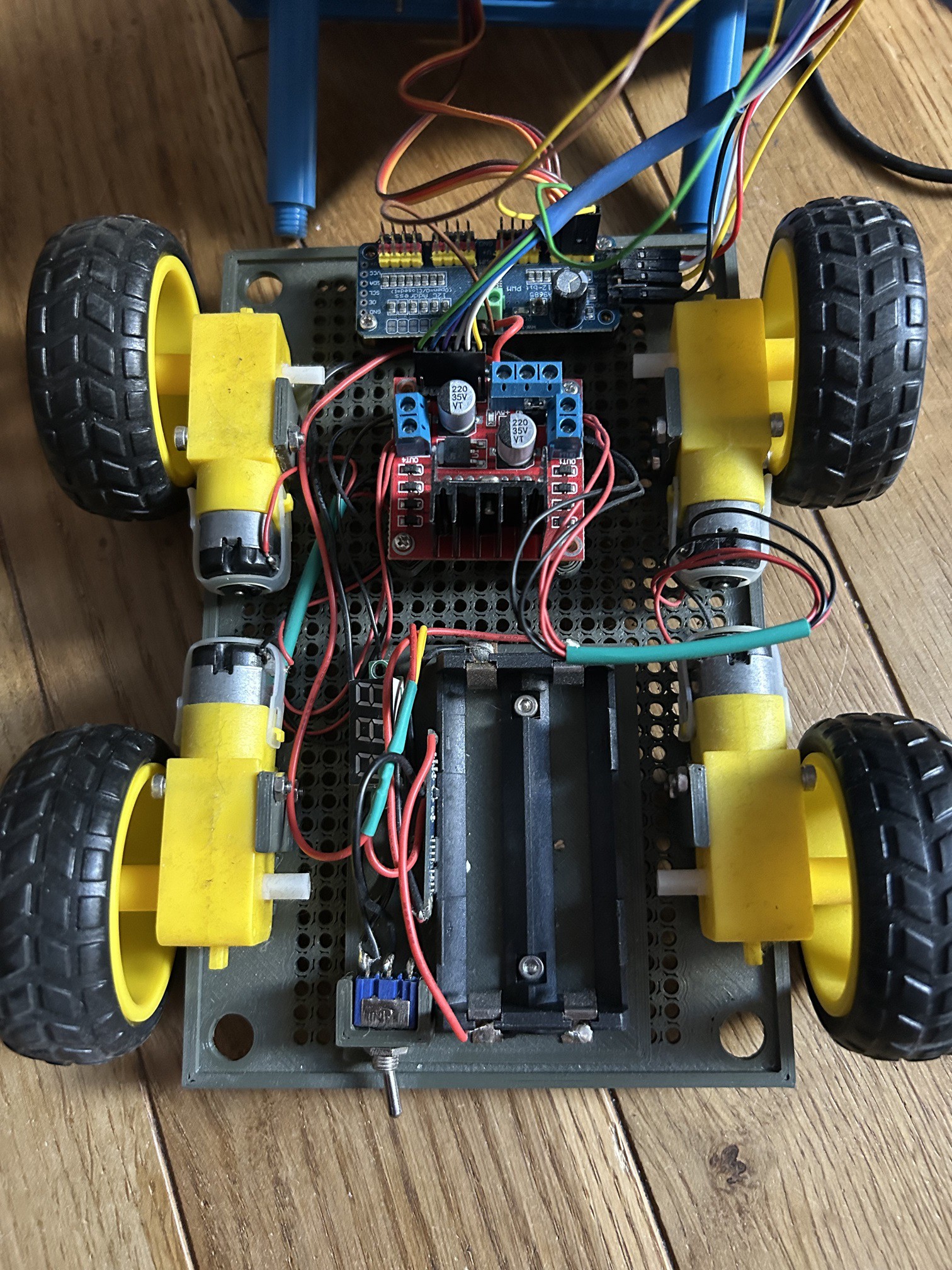
Considering all the info's above I ended up with this wiring:
![]()
and in real life:
![]()
As you can see there are mount points for the motors on the bottom carrier you can find over at pintables as well
Happy tinkering
- L298N Motor driver
-
4Drive setup - Code for the L298N
Running on Raspberry PI Zero 2 I decided to go with python to program the car. You can find my take on the L298N over at github in the file: lib_l298nh_bridge.py
And for you convenience here is a short explanation on the code in this case by Copilot ;o)🧠 Overview
- Purpose: Control direction and speed of two DC motors.
- Hardware used:
- Raspberry Pi (GPIO control)
- L298N Motor Driver (H-Bridge for direction control)
- PCA9685 (PWM controller for speed control)
- Motors connected to left and right channels
📦 Imports and Setup
import board
from adafruit_pca9685 import PCA9685
import RPi.GPIO as gpio
board: Provides access to I2C pins (SCL,SDA).PCA9685: Controls PWM signals for motor speed.RPi.GPIO: Controls GPIO pins for motor direction.
i2c = board.I2C()
pca = PCA9685(i2c)
pca.frequency = 60
- Initializes I2C communication and sets PWM frequency to 60Hz (common for motor control).
max_duty_cycle = 65535
gpio.setmode(gpio.BCM)
max_duty_cycle: Maximum value for PWM signal (16-bit resolution).BCM: GPIO pin numbering mode.
🚗 Motor Control Class:
L298N_motor🔧
__init__MethodInitializes GPIO pins and PCA9685 channels for both motors:
def __init__(self, pca_channel_left, in_left_1, in_left_2, pca_channel_right, in_right_1, in_right_2):
- Sets up GPIO pins as outputs.
- Stores pin/channel references.
- Sets all direction pins to LOW (motors off).
🔄
setDirection(direction)Controls motor direction using GPIO logic:
match direction: case "forward": # Left motor: backward # Right motor: forward
- Uses Python 3.10+
match-casefor clean conditional logic. - Each case sets the appropriate HIGH/LOW signals to the L298N driver to achieve:
forward,backward,left,right, etc.idle: stops all motors.
⚡
setSpeed(scope, speed)Controls motor speed using PWM:
pca.channels[self.pca_channel_left].duty_cycle = int(speed/100*max_duty_cycle)
scope:"LEFT","RIGHT","BOTH"— determines which motor(s) to control.speed: percentage (0–100), converted to PWM duty cycle.
🧪 Example Usage
motor = L298N_motor(0, 17, 18, 1, 22, 23) motor.setDirection("forward") motor.setSpeed("BOTH", 75)- Controls motors on PCA9685 channels 0 and 1.
- GPIO pins 17/18 and 22/23 for direction.
- Moves forward at 75% speed.
Happy hacking !
-
5Drive setup - State machine
In my overall setup I have a client server setup over sockets. And while thinking about it. I wanted to avoid unnecessary communication over the socket e.g. when the car is driving in a straight line. Short explanation:
- The input e.g from a joystick is polled in the program every x milli secs.
- no need to send "keep drinving at 75%" from the client to the server every x milli secs
- Just update when there is a change
Using a state machine seems a pretty nice solution for this - because:
- State machine concepts are explained very well on the net
- There is a python lib for statemachines in python - so no need to create the "to the metal code" on your own if you do not wish to do so ;o)
So I created a class for the "drive" state machine that will utilize the motor driver class mentioned before
You can find the class "DriveControl" in file lib_state_machines.py over at github.
Code explained by Copilot:
🚗
DriveControlClass Explained🧱 Purpose
This class defines a finite state machine to control a robot's movement directions using predefined states and transitions. It interacts with a motor controller (
self.motors) and adjusts speed viaself.master_speed.🔧 Initialization
def __init__(self, motors, master_speed): self.motors = motors self.master_speed = master_speed StateMachine.__init__(self)
motors: An instance of a motor control class (likelyL298N_motor).master_speed: Base speed used for movement.- Inherits from
StateMachineto enable state-based behavior.
⚙️ States
idle = State(initial=True)
forward = State()
forward_right = State()
forward_left = State()
right = State()
left = State()
backward = State()
backward_right = State()
backward_left = State()
- Each state represents a movement direction.
idleis the default starting state.
🔄 Transitions
Each
input_*defines valid transitions between states:Example:
input_forward = idle.to(forward) | forward.to.itself(internal=True) | forward_right.to(forward) | forward_left.to(forward)
- Allows transitions to
forwardfromidle,forward_right, orforward_left. - Also allows staying in
forward(to.itself).
This pattern is repeated for all directions, enabling flexible movement control.
🎬 Actions on State Entry
Each
on_enter_*method is triggered when entering a specific state.Example:
def on_enter_forward(self): self.motors.setDirection("forward") self.motors.setSpeed("BOTH", self.master_speed)- Sets motor direction to
"forward". - Applies speed to both motors.
Special Cases:
- Turning (e.g.,
forward_left,backward_right) sets one motor's speed to0to pivot the robot.
def on_enter_forward_left(self): self.motors.setDirection("forward_left") self.motors.setSpeed("LEFT", 0)🛠 Utility Method
def set_master_speed(self, master_speed): self.master_speed = master_speed
- Allows dynamic adjustment of speed during runtime.
🧠 Summary
This class is a clean implementation of a directional control system using a state machine. It abstracts movement logic into states and transitions, making it easy to manage complex navigation patterns.
Happy hacking!
The modular learning car project
There are tons of arduino or raspi car kits out there but they are not very flexible. With this I want to share my learning journey


Discussions
Become a Hackaday.io Member
Create an account to leave a comment. Already have an account? Log In.