Close
0%
0%

PROTECT Series: DC Power Management Modules

Protect is a series of high-quality DC Power Protection Modules designed for makers using the best eFuses and automotive power path ICs.

Similar projects worth following
Every seasoned electronics maker has had mishaps when applying power to a newly built circuit. These are an essential part of the learning process, as they are mistakes you do not easily forget, but what if you are now working on something and you feel the need to add an additional level of protection?

Many overvoltage and overcurrent modules already exist in the DIY electronics space. These generally are made of various combinations of fuses, diodes or MOSFETs. These components all have their use cases, but in general, a lot of these designs could be improved in terms of efficiency, adjustability and scalability.

At PN Labs, we have already designed and released two high-performance power protection modules for makers: the Protect, and the Protect Nano.

Join us over the next few months as we develop the Protect+, which will combine elements of both the Protect and Protect Nano and be designed for higher power with more features.

This project is sponsored by PCBWay!

The goal is to create a device that has over/under voltage, reverse polarity, reverse current and short circuit protection in the most power-efficient way for a reasonable price.

The Protect series addresses the areas of improvement as follows:

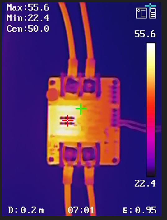
Efficiency: A lot of designs use P-channel MOSFETs, usually for achieving reverse polarity, but these are inherently inferior to N-channel MOSFETs due to the higher carrier mobility of n-type silicon. Even if an efficiency loss of a few percent is tolerable, it drastically increases the thermal load on the PCB which reduces the overall current capability of the board. We used low-Rds N-channel FETs to achieve efficiencies >98% (typ.) on the Protect, and we will do it again on the Protect+.

Adjustability: Most DIY and commercial designs are purpose-built for a specific unit. Since the Protect+ is intended to be reusable between multiple projects, it will be built with potentiometers to adjust the voltage cutoffs, while also making provisions to be easily replaceable with a fixed resistor. The appropriate resistor will be able to be calculated by entering the desired cutoff values in a calculator, or with simple equations.

Scalability: By adding an ideal diode input stage, current from the module is prevented from flowing backward into the supply, effectively isolating individual supplies from each other when their outputs are connected in parallel. When combined with some enable or reset functionality for power path control, this provides the foundation for building larger, more complex systems that utilize multiple power supplies.

Proposed features:

  • 4-60 V operating voltage range
  • XT60 PW Male and Female connectors
  • Up to 30 A of continuous current capability, 45 A burst current rating
  • Latch-off short circuit protection, resettable via switch or opto-isolated signal
  • Non-isolated current monitor with programmable gain (via resistor jumper)
  • Blocking voltages of up to 75 V 
  • SAFE LEDs with opto-isolated fault and reset signals
  • Optional jumper for disabling all onboard LEDs/optoisolators so upon entering a FAULT condition, the board enters an ultra-low current mode that wastes very little battery power.

Roadmap:

1. Collect feedback from the community on overall design.

2. Design the prototype product and perform testing to validate the core functionalities.

3. Crowdfund on Kickstarter or Crowd Supply for the first batch and develop Quality Control jigs

Protect_plus Diagram.jpg

Block Diagram of showing functional elements of the Protect+

JPEG Image - 135.90 kB - 10/27/2025 at 05:58

Preview

Protect_plus.drawio

File for editing Protect+ block diagram in draw.io

drawio - 14.54 kB - 10/27/2025 at 05:58

Download

  • 1 × KXN-3030D Power Supply 30V, 30A, 900W
  • 1 × HIKMICRO B1L Handheld Thermal Camera 160x120 resolution

  • Steady-State Thermal Power Testing on the IT6015C

    PN Labs4 days ago 0 comments

    The most important features of the Protect+ is the ability to carry a high amount of current, ideally in the range of 30 to 40 A continuously.

    To do this, I used 3 MOSFETs in parallel for the high-side blocking and reverse blocking FETs, each with about 2.1-2.5 mOhm of on-resistance.

    The PCB used is 4-layers, with 2 Oz outer and 1 Oz inner.

    Shown below is a snapshot of the results obtained testing at 30 V, 29.5 A after about 5 minutes of continuous operation.


  • First Functional Prototype In - Sponsored by PCBWay!

    PN Labs11/25/2025 at 07:31 0 comments

    Its been a while since I updated this feed, so here it is with progress:

    - Changed from DIP switches back to potentiometers for voltage adjustment - continuous adjustment is better for something as sensitive as voltage cutoffs

    - Started designing a calibration jig that can measure the voltage cutoffs of each board. This is because when doing something as critical as undervoltage protection of lithium cells, having a typical 1-3% error in the voltage cutoff equation (as seen from internal testing of Protect modules) makes a difference in protecting the battery and the amount of energy that can be drawn before shutdown.

    - First functional prototype has been received by PCBWay and hand assembled! A few differences I noticed when ordering compared to other board houses:

    • PCBWay supports higher copper weights like 3 Oz, 4 Oz, and much higher, whereas other board houses like JLCPCB can only do 2 Oz currently. This is very important for high current designs (like the Protect+) where large copper pours (and stitching together different pours on different layers) are necessary to draw heat away from components on the board.
    • I found the green solder mask on the PCBway boards to be much more visually appealing and higher quality than what I am used to. The dark olive color makes the board look very premium, and it reminds me of the PCBs you sometimes find in precision equipment with an ENIG finish. I've put a comparison between the Protect+ prototype and another board below.
    • One mistake I made when ordering is not understanding the difference between the framework and non-framework stencil option. I think that the website pictures on the ordering page explaining the differences could be made more clear to show that Non-framework is the one most people hand prototyping would want (they should delete the confusing holes on the sides). I ordered the one with framework and it came separately, glued to a big aluminum frame which was great but somewhat unnecessary for my hand assembly. 

    The prototypes cutoff at the right voltages and everything seems to be in order, so the next step is to do some preliminary power testing to see how the board copes with in-rush current, plus its steady state thermal profile at different power levels (2 FETs or 3 in parallel?).

  • Improving Ease of Voltage Limit Adjustments, plus others!

    PN Labs10/27/2025 at 06:14 0 comments

    - Changing from using potentiometers to using resistor arrays with DIP switches to improve accuracy and remove the need for a user to have their own resistance meter to set the required Over and Under voltage cutoffs.

    - Since there is no longer a potentiometer being used, it is no longer necessary to restrict the operating voltage ranges to 30 V and 60 V versions. Just one 4-60 V version will be made targeting 30 A continuous current.

    - A lower voltage version going up to 30 V but doing higher amperage is very possible, just by using a higher current connector and using lower resistance FETs. Interested in hearing what projects could use this.

    - The over-current circuit breaker will also use its own DIP switch for ease of use

View all 3 project logs

Enjoy this project?

Share

Discussions

Similar Projects

Does this project spark your interest?

Become a member to follow this project and never miss any updates