 Next Builder
-
1CAD & 3D Printing
![]()
![]()
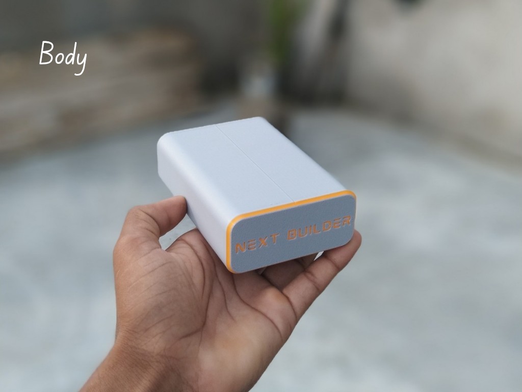
To start this project, I designed this diy mini WiFi UPS CAD using Fusion 360. It’s a simple and compact design that’s easy to print and assemble. For 3D Printing, You can directly download the required STL files below:
- Body.stl
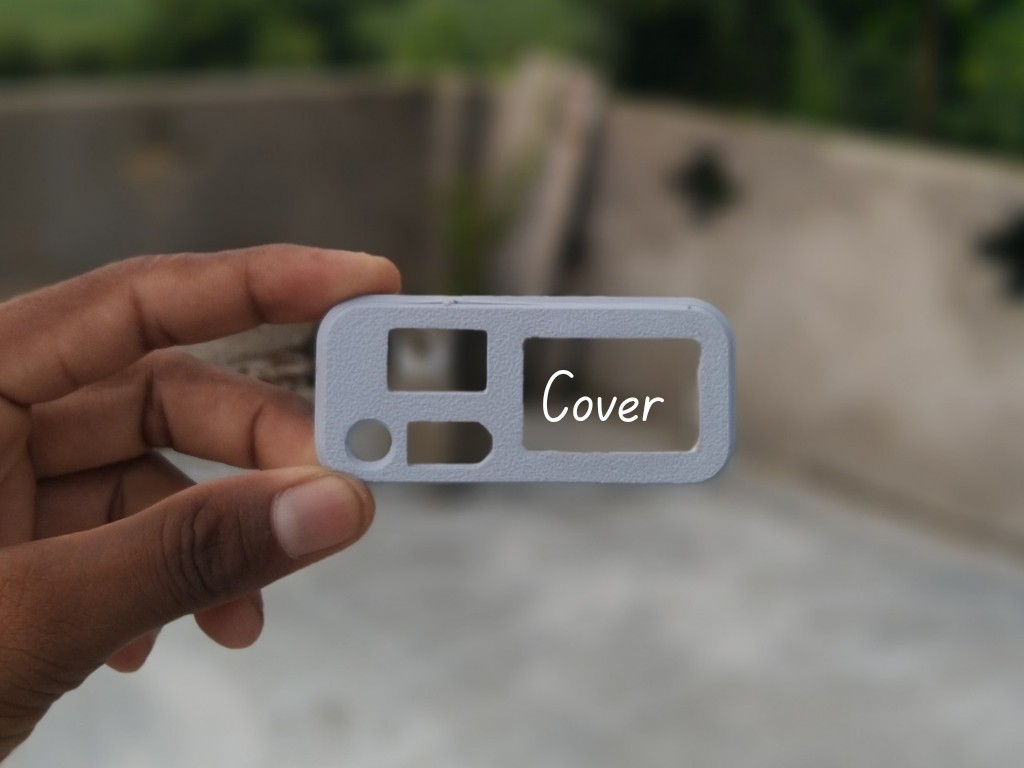
- Cover.stl
For 3D printing, I Recommend PCBWay, a professional 3D printing service known for its high precision, affordable pricing, and wide range of material choices. They support advanced technologies like SLA, SLS, MJF, and FDM, delivering smooth and durable parts that are ideal for both prototypes and final builds.
One of the best things about PCBWay 3D printing is their fast turnaround time and reliable worldwide shipping, making it super convenient for hobbyists, students, and professionals alike. Whether you’re just getting started or working on a serious engineering project, PCBWay is a great choice.
👉 Use the link to get an exclusive discount on your first 3D printing order from PCBWay
-
2DC Jack Assembly
![]()
![]()
![]()
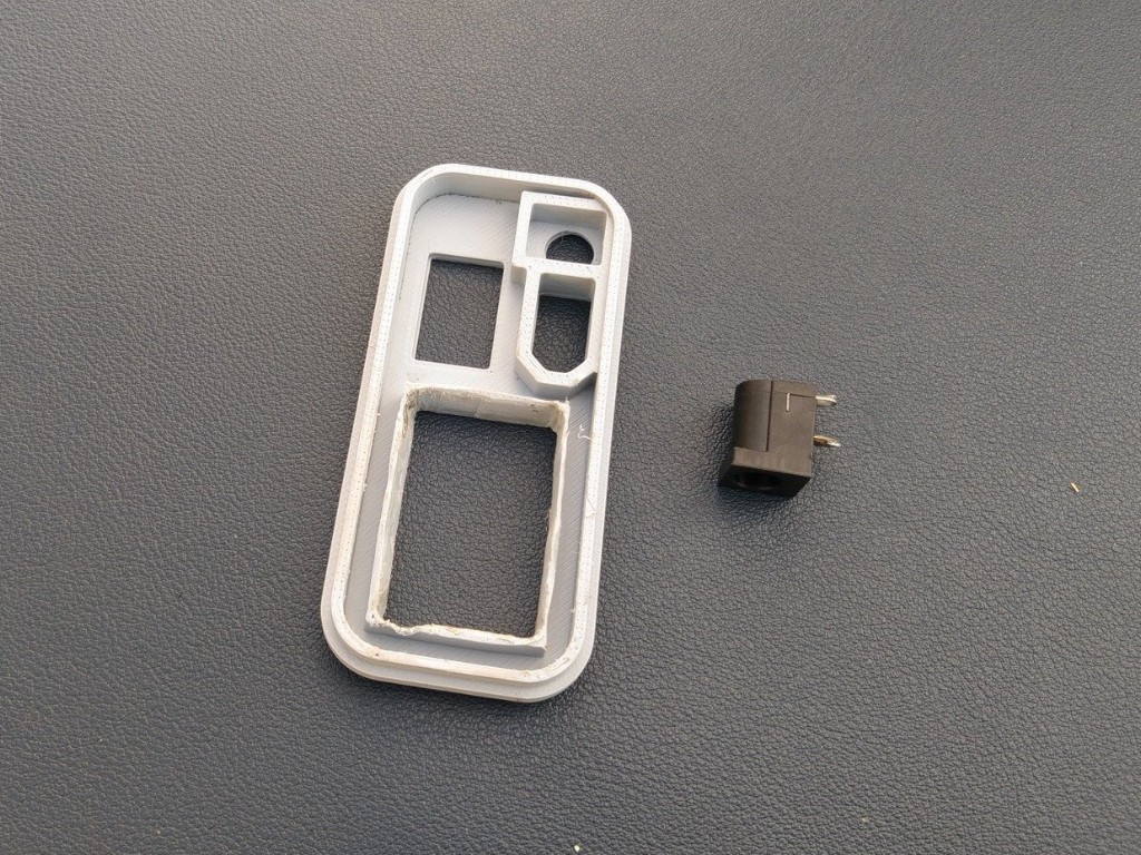
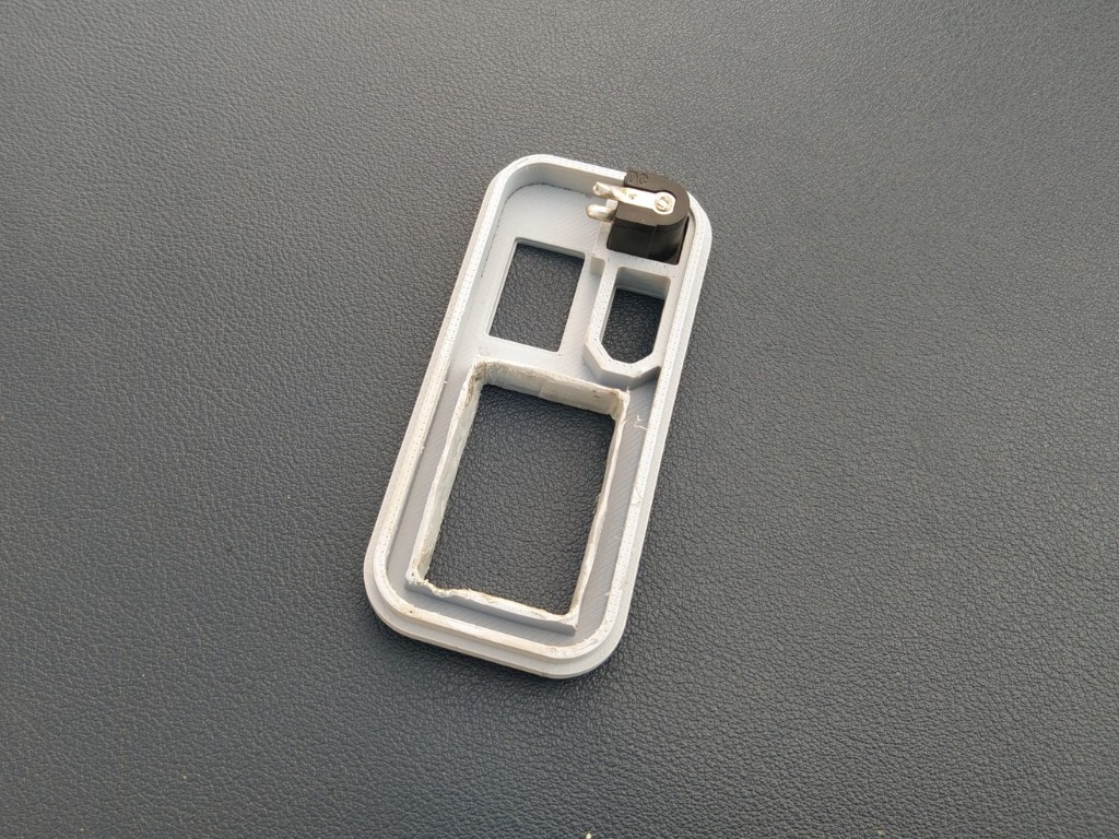
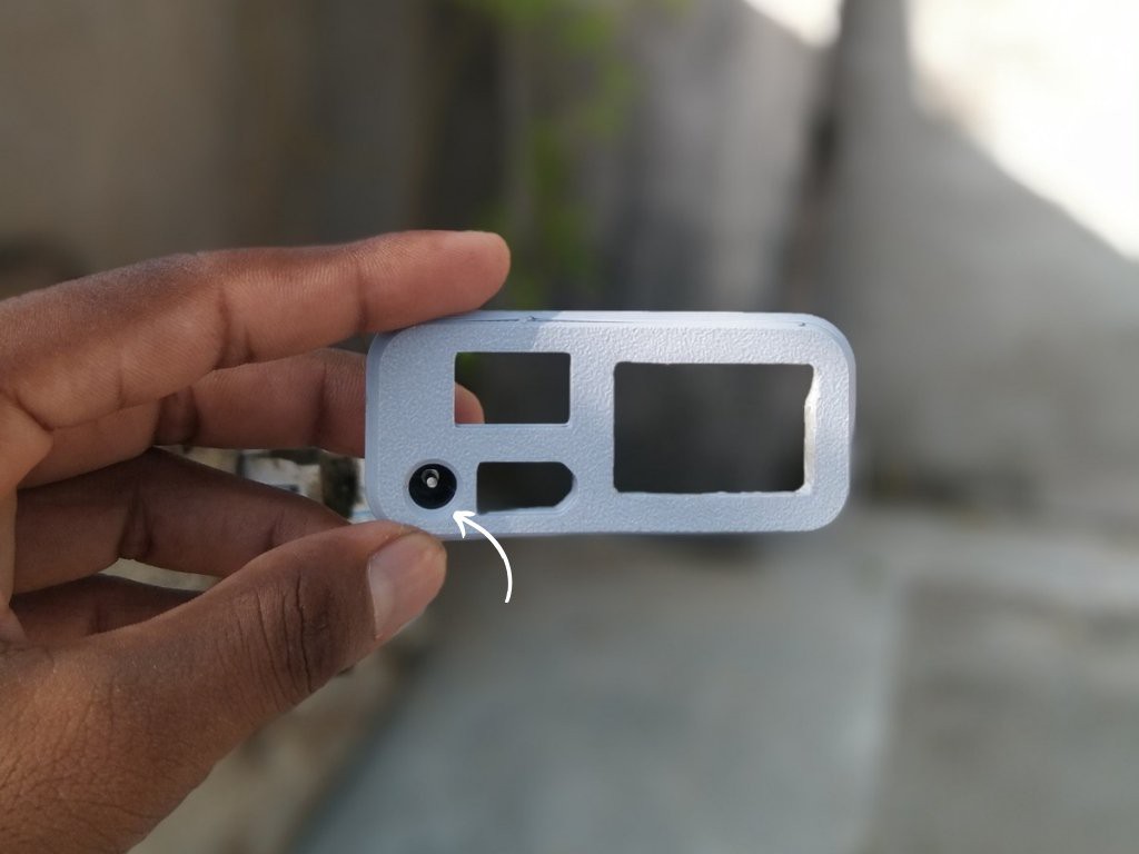
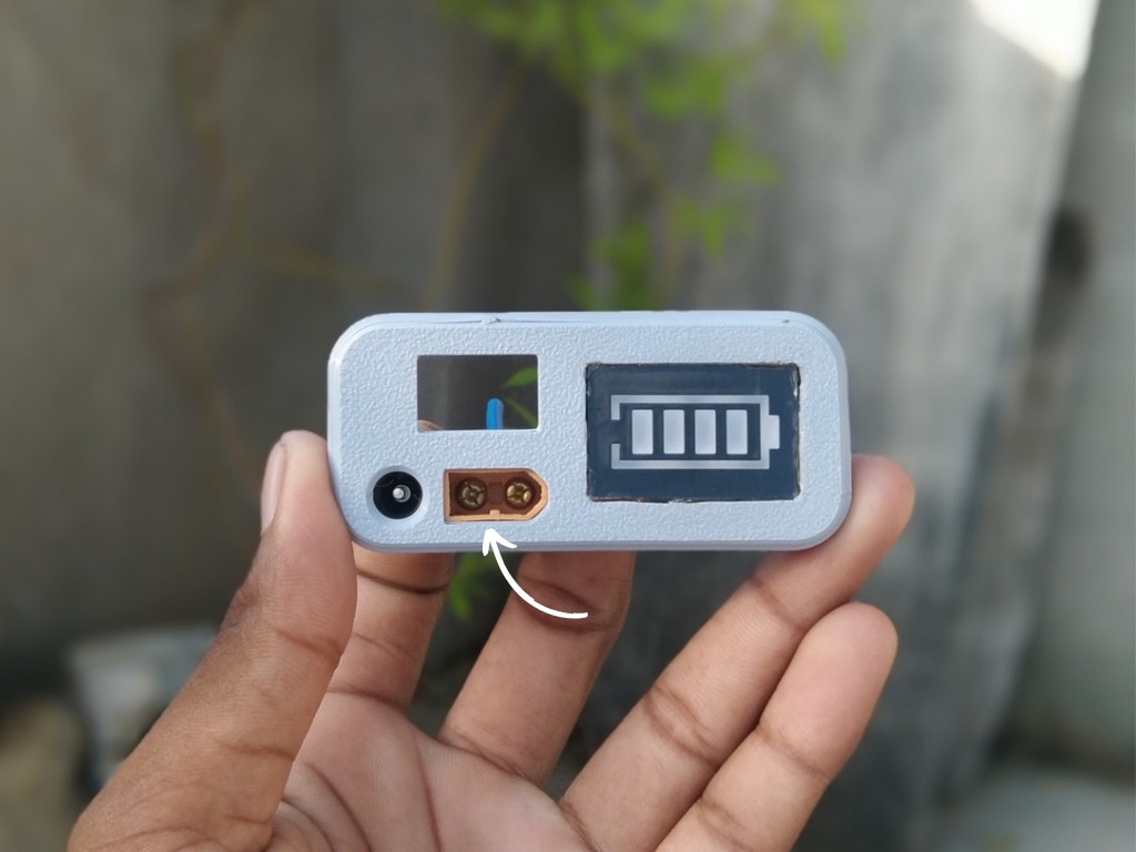
Insert the DC 5525 female jack into its dedicated slot on the cover and secure it with a small amount of super glue, making sure the orientation is correct
-
3Capacity Indicator Assembly
![]()
![]()
![]()
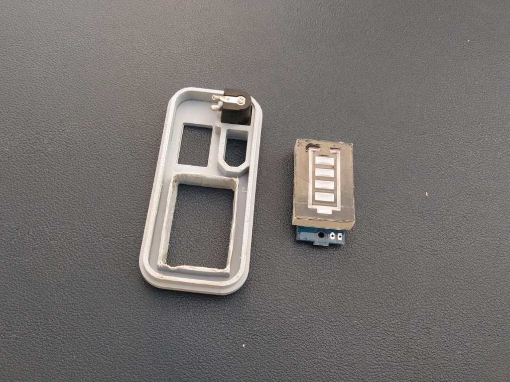
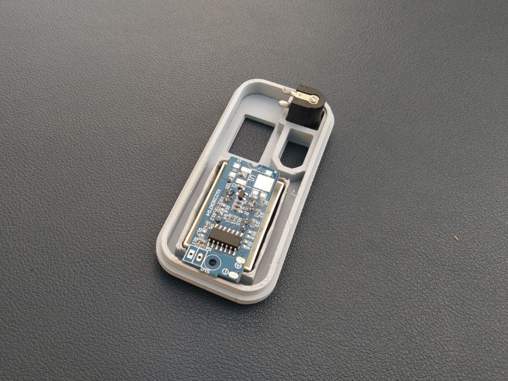
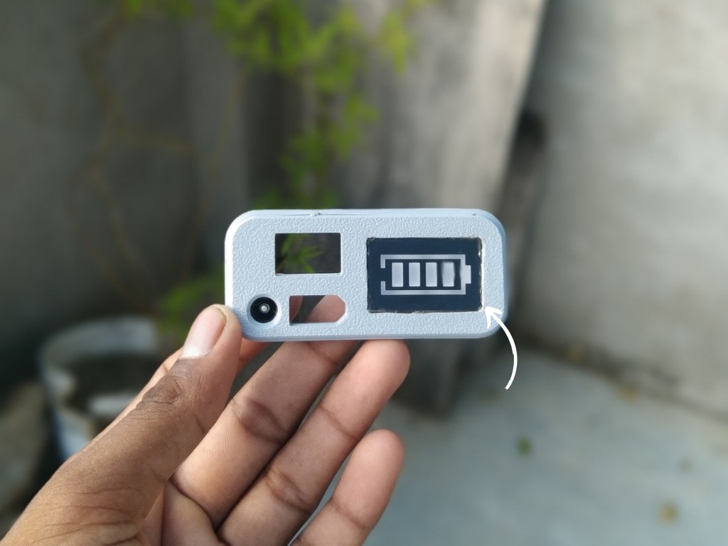
Place the battery capacity indicator module into its slot on the cover and fix it with a small amount of super glue, ensuring it sits flush and aligned.
-
4XT60 Connector Assembly
![]()
![]()
![]()
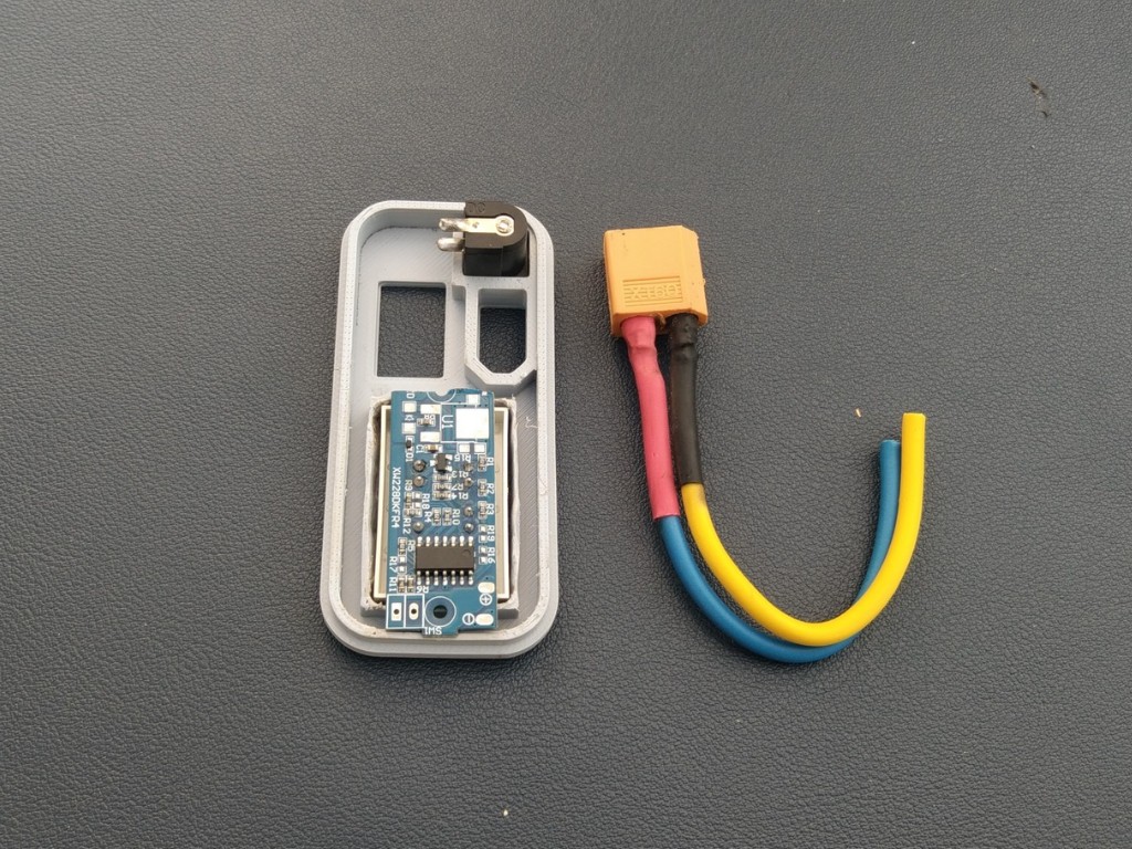
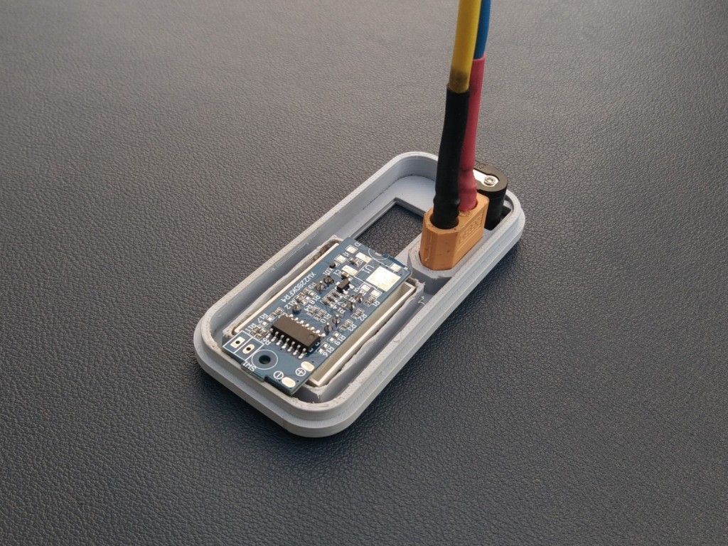
Insert the XT60 connector into its slot on the cover and secure it firmly with a small amount of super glue, keeping the orientation correct for easy connection later.
-
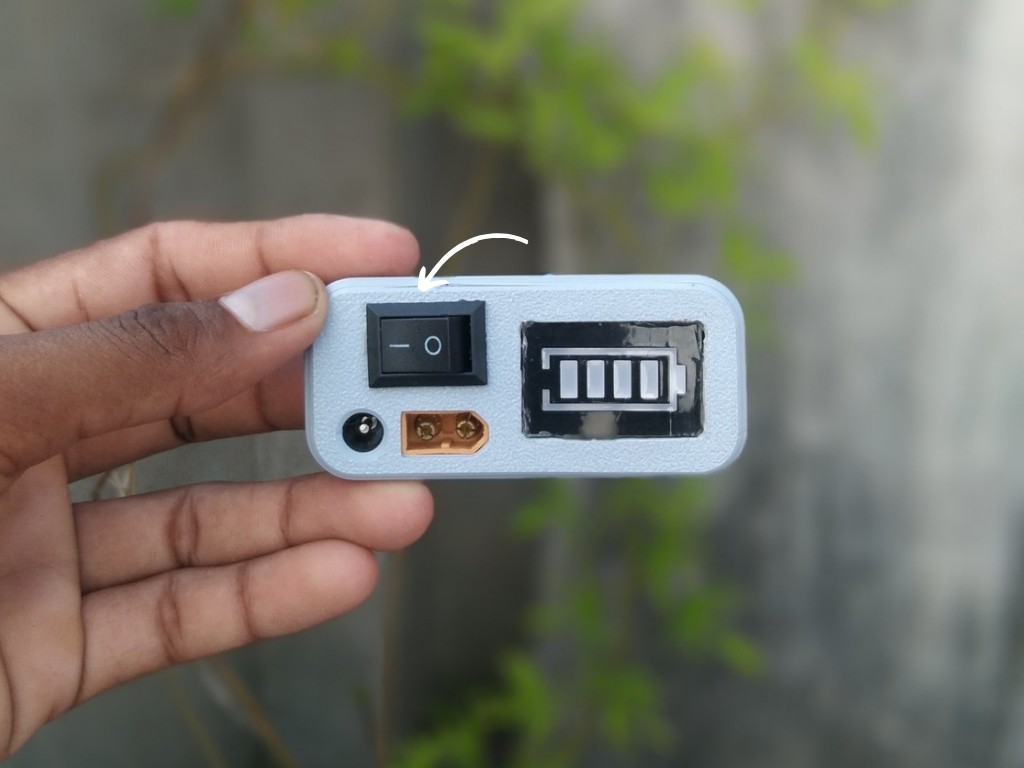
5Switch Assembly
![]()
![]()
![]()
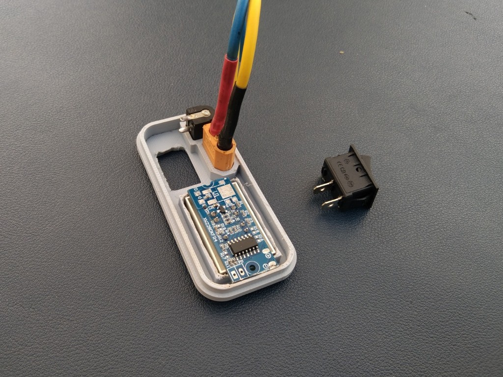
Place the switch into its slot on the cover and fix it securely with a small amount of super glue, making sure it is properly aligned for smooth operation.
-
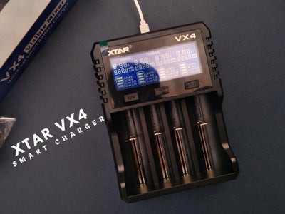
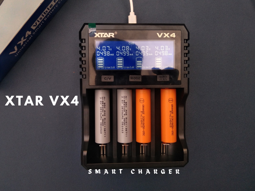
6Charging Battery
![]()
![]()
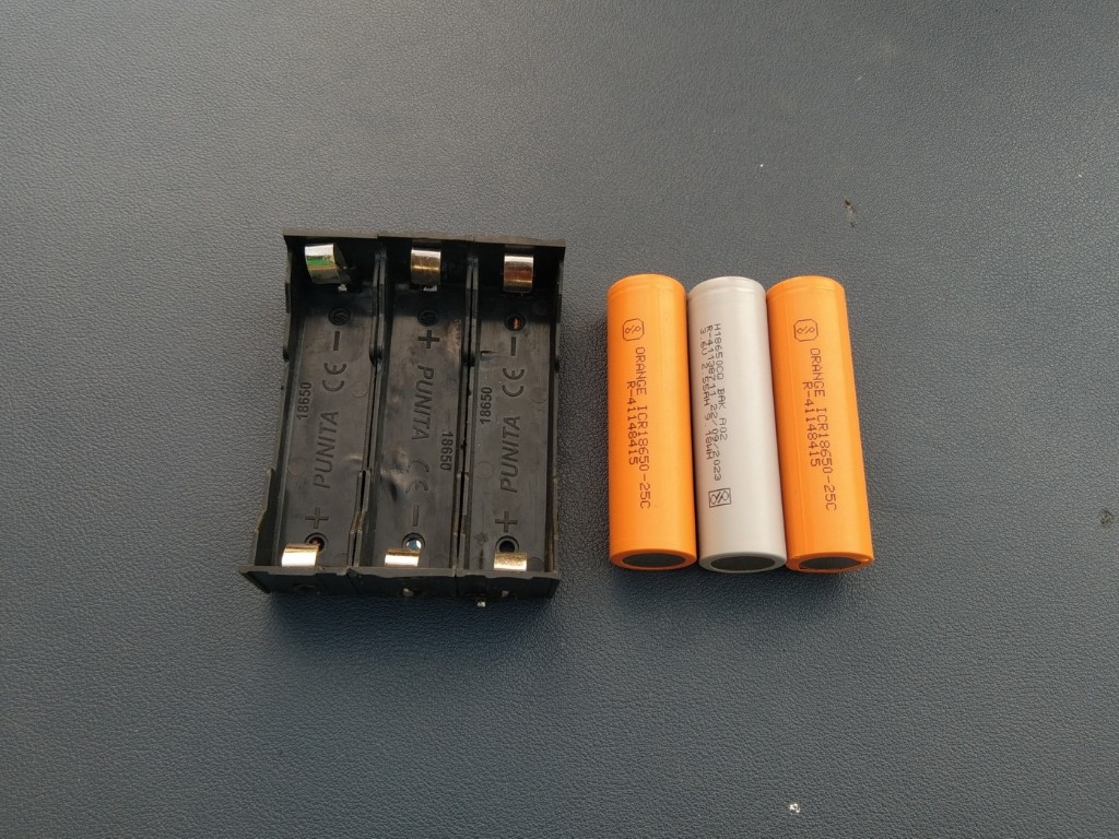
Before assembling the 3S pack, it’s important to fully charge each 18650 cell. This ensures all the batteries start at the same voltage, which is critical for safety and long-term performance. I used my XTAR VX4 smart charger to charge the cells individually before wiring them into the pack.
-
73S Battery Pack
![]()
![]()
![]()
![]()
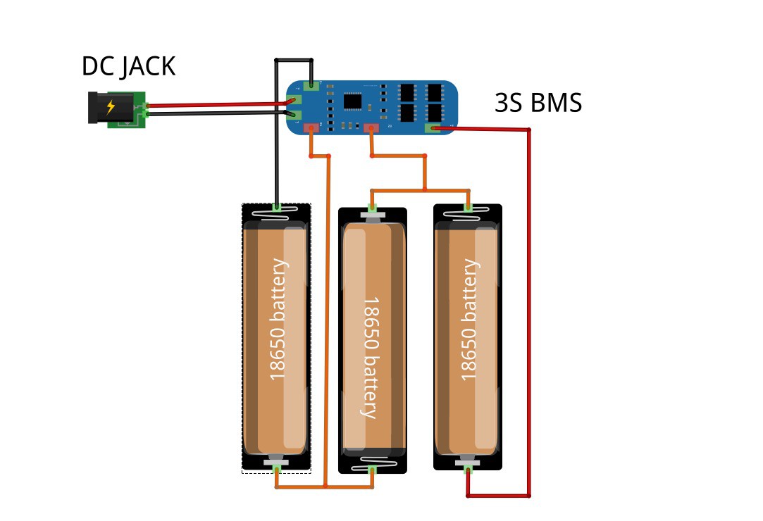
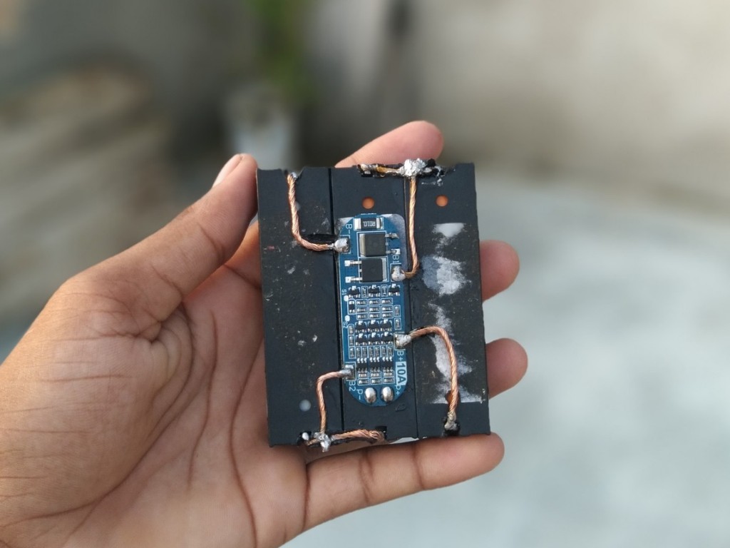
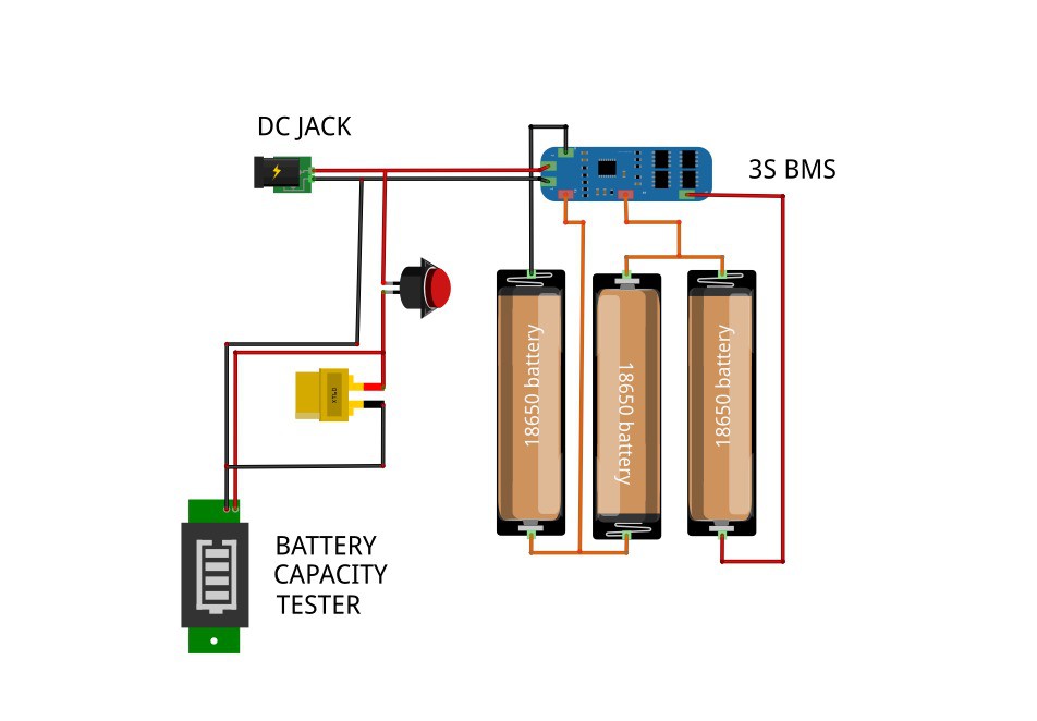
Connect the three 18650 cells in series to form a 3S battery pack (11.1V nominal). Follow the wiring exactly as shown in the diagram:
- Cell 1 (-) → B– of BMS
- Cell 1 (+) → Cell 2 (–)
- Cell 2 (+) → Cell 3 (–)
- Cell 3 (+) → B+ of BMS
- Junction between Cell 1 (+) & Cell 2 (–) → B1 of BMS
- Junction between Cell 2 (+) & Cell 3 (–) → B2 of BMS
Use the P+ (red wire) as the positive input/output and the P– (black wire) as the negative input/output.
⚠️ Safety Note: Always verify polarity twice before soldering, and keep connections insulated to avoid shorts or overheating.
-
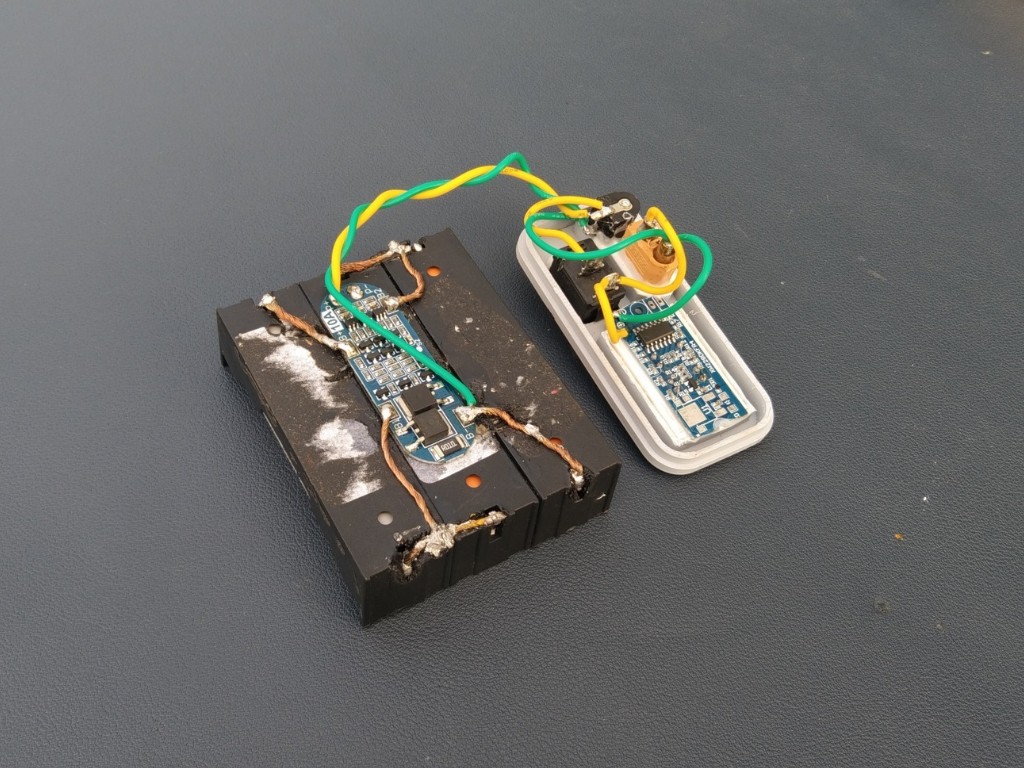
8Connection
![]()
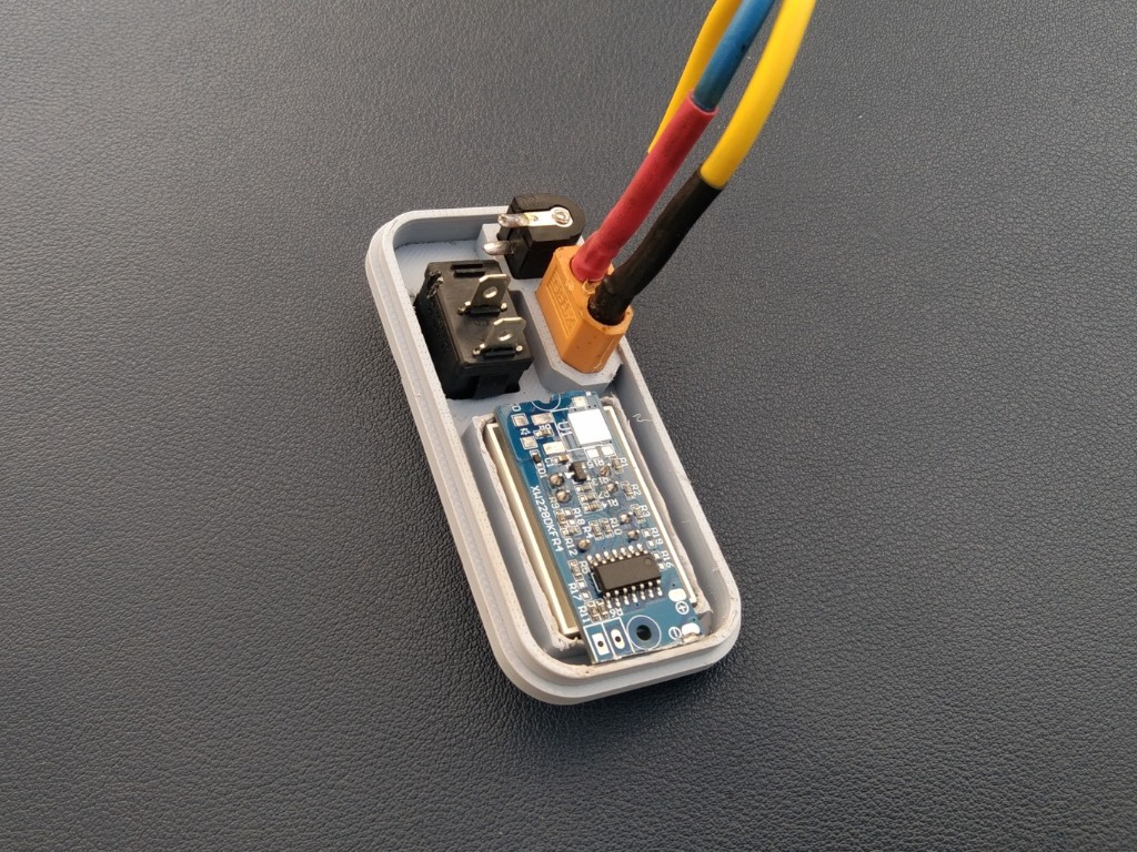
Once the battery pack is complete, Now it’s time to wire everything together carefully. Follow the sequence to avoid mistakes, you can also check the provide circuit Diagram for clear understanding.
- DC Jack positive (+) → Switch → XT60 connector + Battery Capacity Indicator
- DC Jack negative (–) → Direct to BMS negative (P–)
- BMS output (P+ / P–) → Goes to XT60 connector and Battery Capacity Indicator
This ensures proper charging through the DC jack, balanced protection via the BMS, and safe output through the XT60.
-
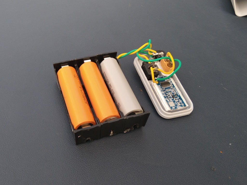
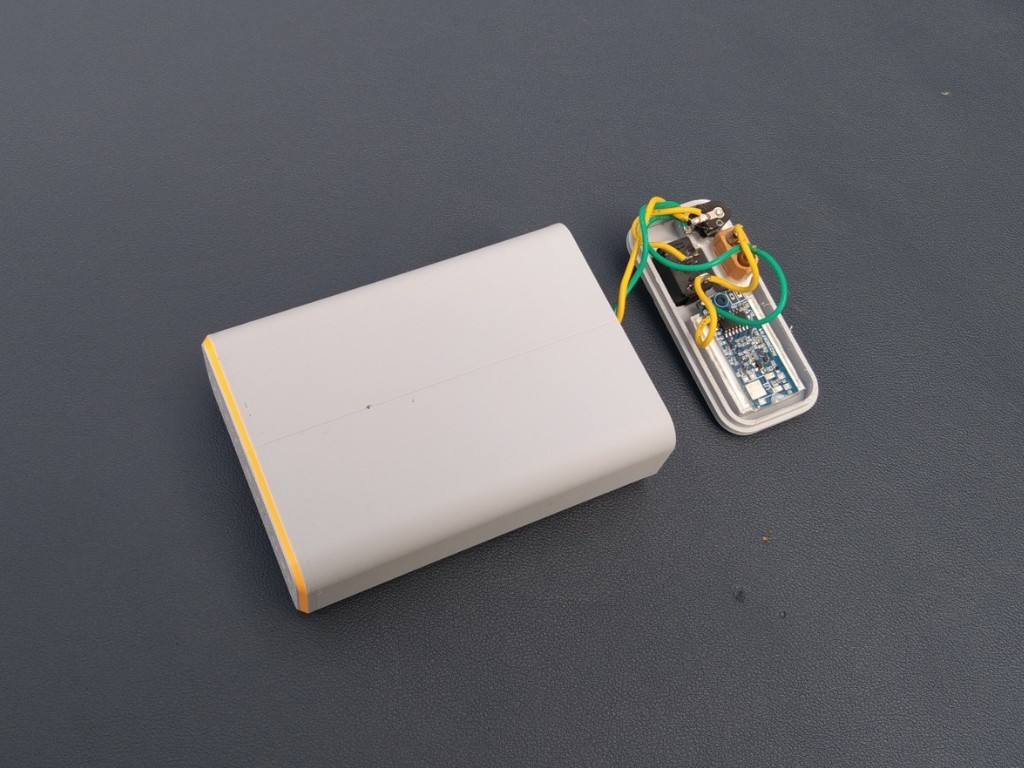
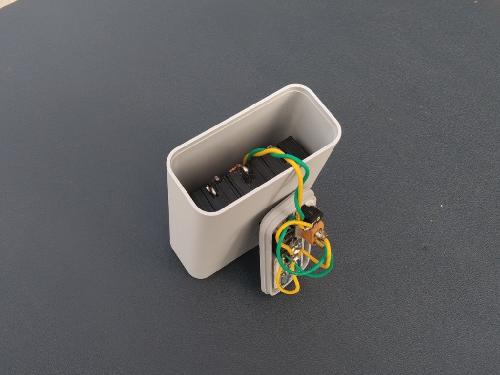
9Battery Assembly in Case
![]()
![]()
![]()
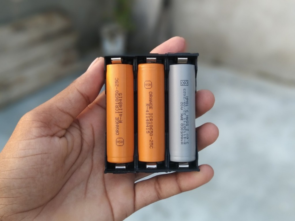
Insert the 3S battery pack into the 3D-printed case carefully, making sure it fits in the correct orientation. Once positioned, apply hot glue around the edges to secure the pack firmly in place and prevent movement inside the case.
-
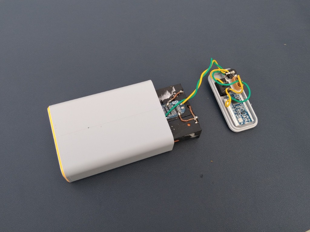
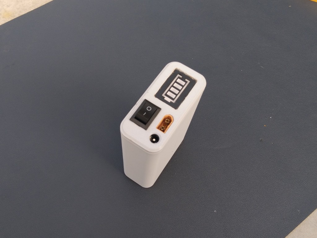
10Final Assembly
![]()
![]()
![]()
Place the cover onto the case and secure it with super glue. Before sealing, carefully double-check all wiring connections to ensure everything is correct and secure. Once confirmed, close the case firmly for a clean and durable finish.
DIY Mini UPS For WiFi Router (Easy To Build)
Stay connected during power cuts! A compact, affordable Mini UPS that keeps your WiFi router running when the electricity fails.
Discussions
Become a Hackaday.io Member
Create an account to leave a comment. Already have an account? Log In.