 JP Gleyzes
I wanted a wireless buddy box for my Radiomaster TX16s
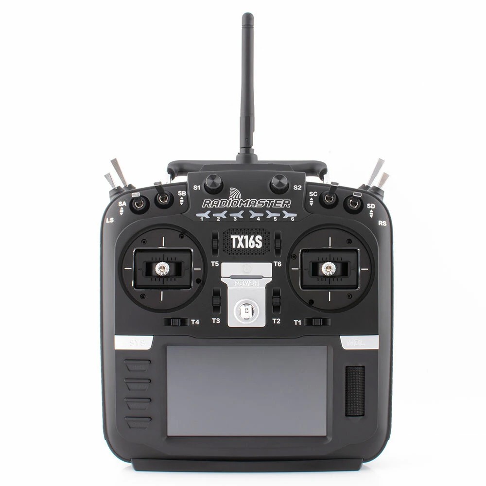
This buddy box would allow to wireless link two TX16s in Master/Trainer mode.
Radiomaster is already selling this kind of module.
However their modules need to be linked (soldered with) mini receiver to work. Furthermore they are "one way" modules (trainer to slave) and finally quite expensive...
So decided to build mine with the following specifications:
- cheap (two fully working modules for less than 20$)
- auto configuration as master or slave or vice versa
- auto binding between two modules
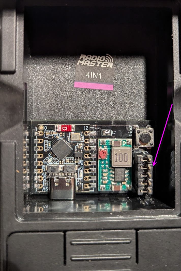
- fully hidden into the "external module" compartment (no dangling wire outside the radio))
- no modification into the TX16s
- no firmware modification of your TX16s (stock EdgeTx firmware)
- high speed wireless communication with about 20m range
- automatic On/Off of the buddy boxes via EdgeTx
- compatible 16 channels SBUS and PPM signals
- extensible to further options (teasing: a bluetooth low energy joystick and more to come !)
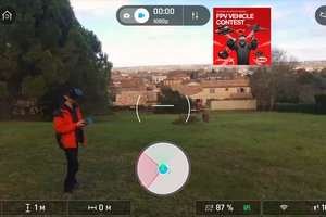
Before going further here is the final result in video
Schematics
Schematics couldn't be more simple !
Version V1.0 is powering the ESP32 via the 5V pin
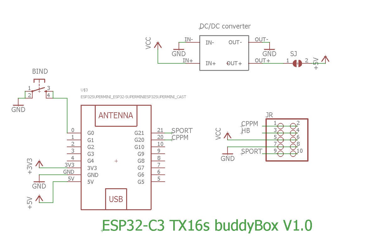
V1.1 is powering the ESP32 via the 3.3V pin. Apart this, both boards are strictly identical.
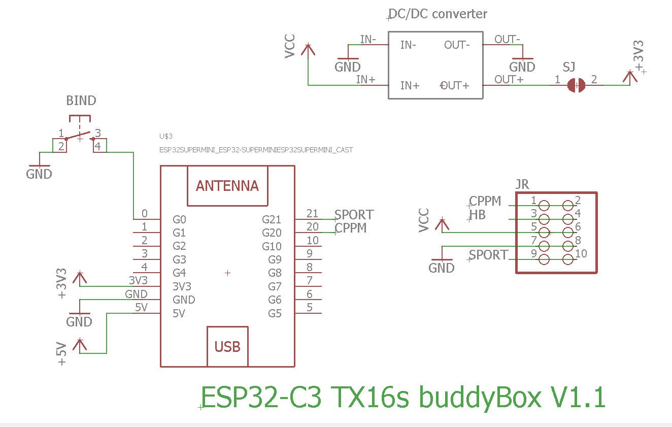
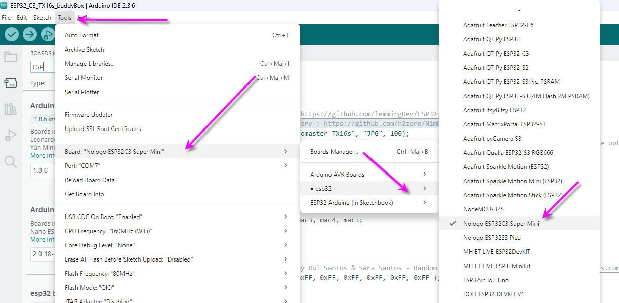
Basically, almost nothing but an ESP32-C3 Super mini
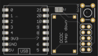
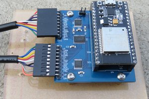
PCB
PCB is also simple and must be small enough to be hidden into the "external module" compartment of the radio
The PCB was kindly sponsored by PCBWay and is as usual of excellent quality.

You can order it here : PCBWay shared project. It's cheap, delivered very fast and so professional looking!
and if you are new to PCBWay please use this affiliated link : https://pcbway.com/g/o35z4O
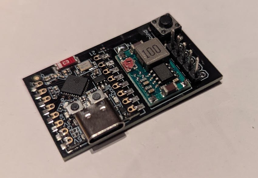
soldering the board is very simple.
When finished it can be placed into t the external bay of the radio and connected with 5 "jumpers" glued together
Power
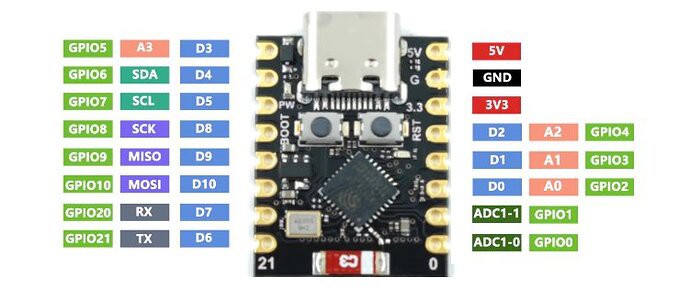
As said above, to power the ESP32-C3 "supermini" MCU we need either 5V or 3.3V.
- Powering with the 5V pin will turn on the red led of the ESP32-C3 while switching also on a linear 3.3V voltage regulator into the board
- Powering with the 3.3V will NOT turn on the red led of the ESP32-C3 and will bypass the internal linear 3.3V voltage regulator
- V1.0 of my board uses the first option. You will thus need a 5V DCDC step down
- V1.1 of my board uses the second option. You will thus need a 3.3V DCDC step down
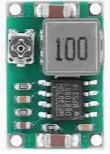
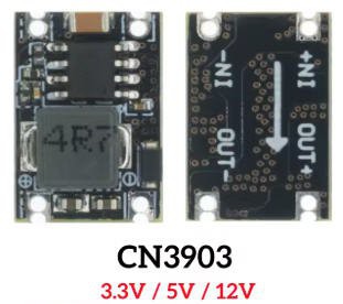
If you use an adjustable DCDC converter as below:
You will have first to tune the trim pot value in order to get 3.3V or 5V output (do not power anything else before...) when this is achieved, you can paint the trim pot with a drop of nail varnish to fix the potentiometer then (and only then) solder the SJ solder pad on the top side of the PCB. The 3.3V or 5V will now flow to the ESP32
if you use a fixed output DCDC stepdown converter as below:
You will have to order the right one (either 5V for V1.0 board or 3.3V for newer V1.1 board)
I strongly advice that you measure output voltage before soldering the SJ solder pad on the board !
Finally which solution is the best V1.0 or V1.1 ?
The V1.1 version is slightly better as the internal linear voltage regulator which drops down 5V to 3.3V, into the ESP32 Super mini, will be bypassed; leading to less power consumption into the battery of your radio.
Indeed DCDC step down converters have a much better efficiency than linear regulators.
Although the gain could be considered as "marginal", the V1.1 board is now the default solution if you order the PCB on PCBway site.
I must say that It's not worth buying the new V1.1 for those (like myself !) who already have a V1.0 board
How does it work ?
To understand how my module works we must first have a look at the JR connector into the external module bay on the back side of the radio.
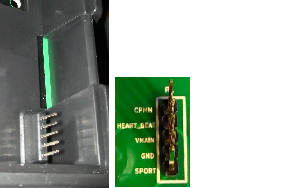
two pins are very interresting :
- CPMM
- SPORT
while two more seems to be self explainatory (but...
Read more »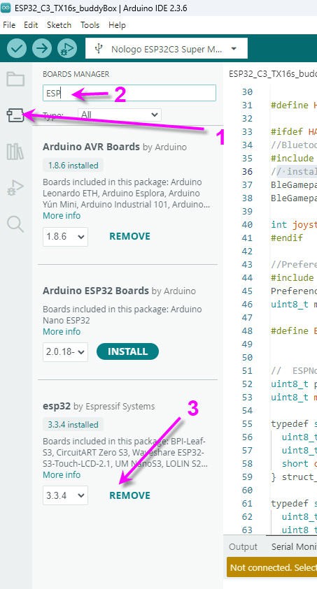

 Adrelien
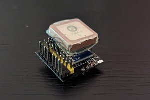
 mulcmu