 Omer Inbar
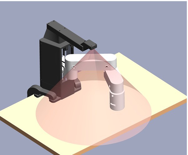
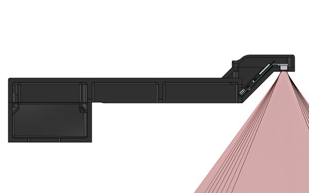
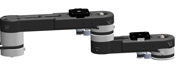
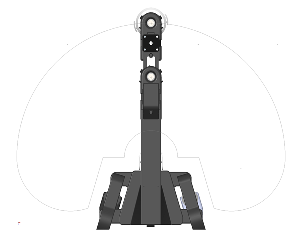
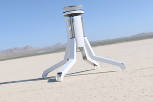
I decided to go with a PRRR SCARA configuration. Since my goal is maximizing value for cost, I very quickly decided on SCARA which I think can be made very useful while eliminating several elements of complexity relative to articulated arm. Its motion in the XY plane is separated from the Z translation which really simplifies the kinematics, and its rotational joints don't resist the load and so can stay very light.
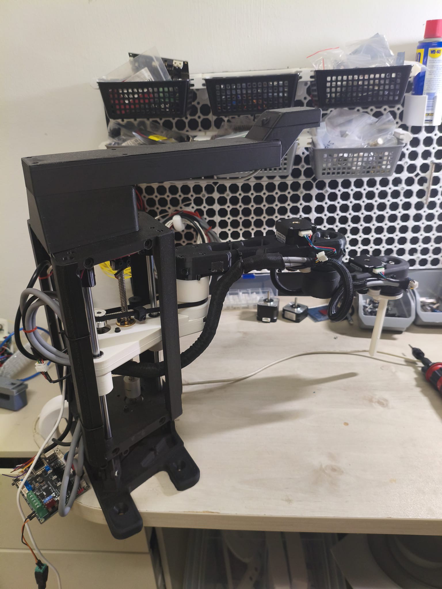
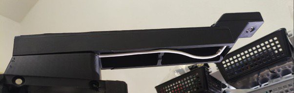
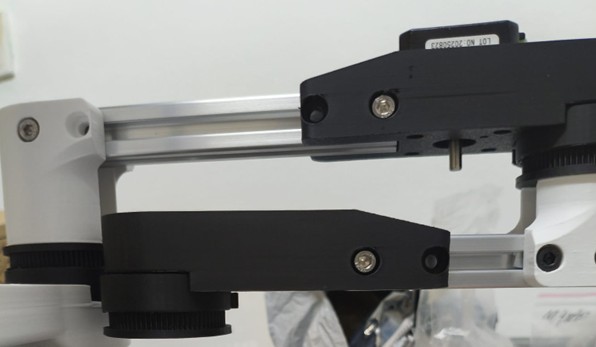
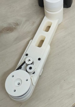
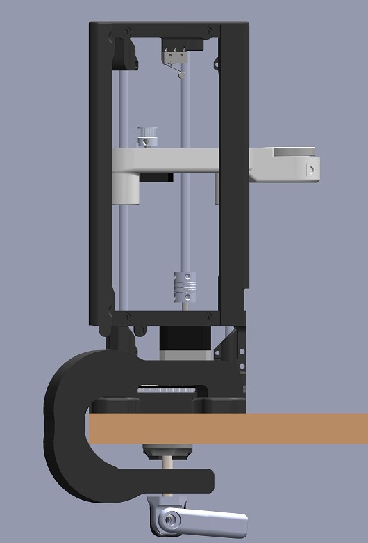
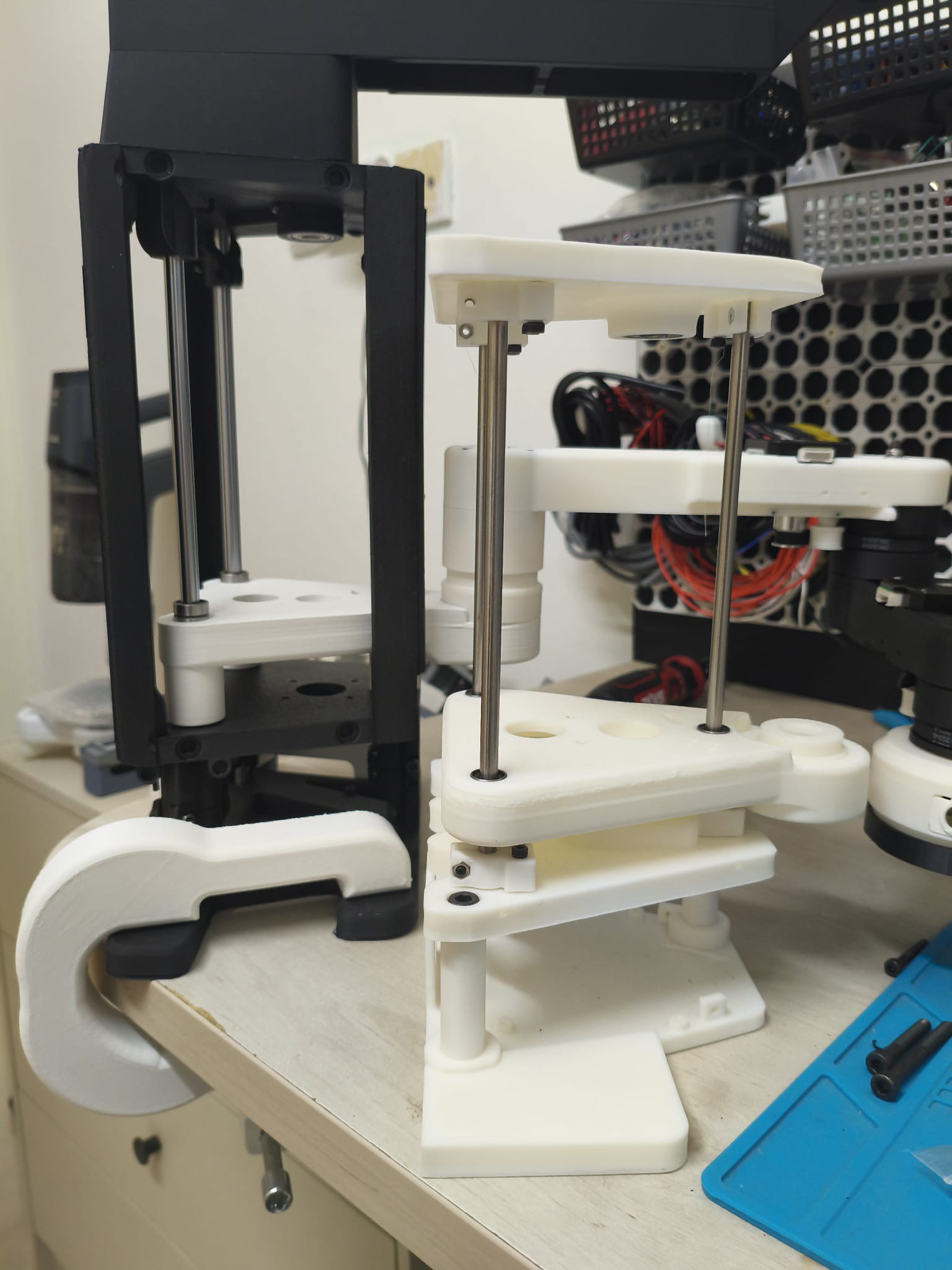
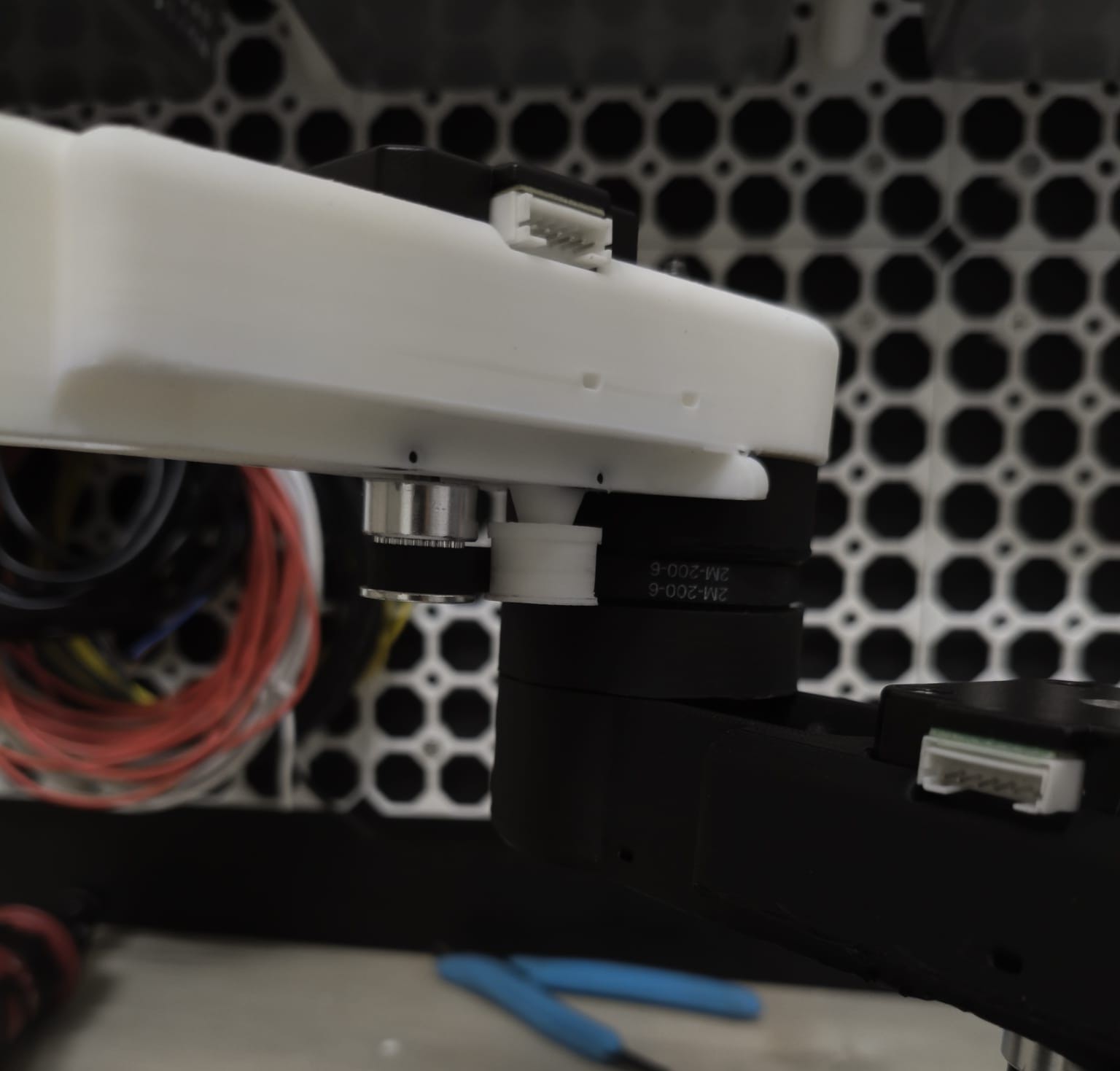
The arm will be actuated by 4 nema17 stepper motors, a nice beefy one directly coupled to a lead screw for the Z axis, and 3 slim ones that will rotate the 3 joints couplers via timing belts.
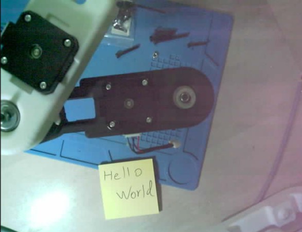
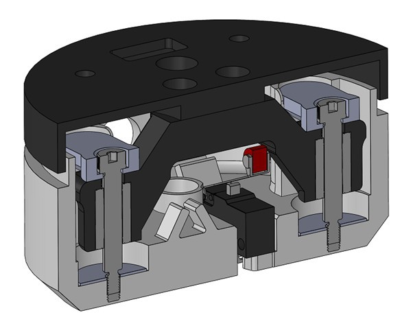
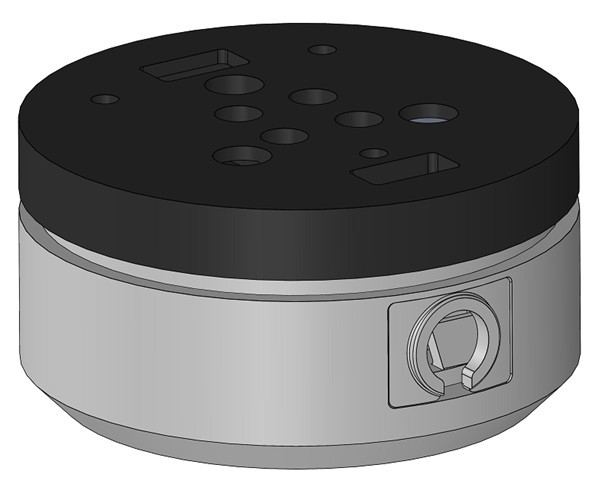
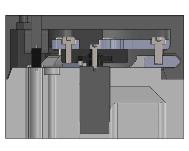
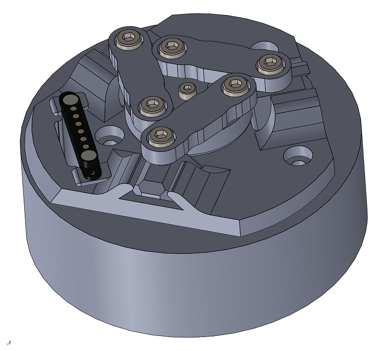
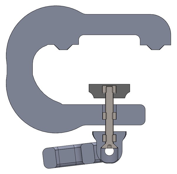
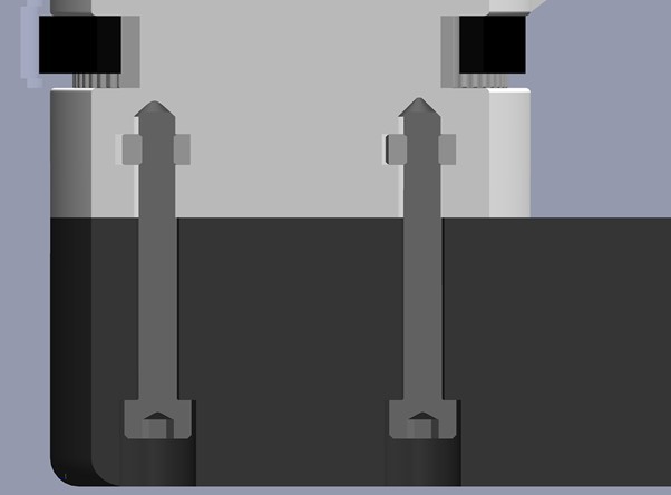
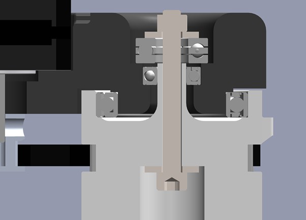
Below the wrist I have a Z compensation module that will help with tool changing, vision based picking and Z axis collision detection. Lastly there will be a servo controlled tool changing mechanism with a 6 pin magnetic pogo connector that will feed tools with power and up to 4 IO pins (one of the pins will be taken for connection verification).
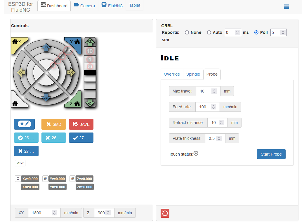
The controller I went for is the Fysetc E4. It is ESP32 based so i get built-in wireless and it has 4 integrated TMC2209 drivers which are smart, quite and should enable sensor-less homing. But most important, i get to use the awesome FluidNC firmware. It is an open-source ESP32 optimized CNC firmware that i found and it simply has everything i needed for this project.
I think I will go with a 0.3m reach and hopefully up to 0.5 kg payload capacity. The main mechanical challenges are fighting flex in the tower and first joint and ensuring smooth stable Z axis movement. Iterations in their design should enable increasing reach and payload.
My biggest inspiration for this design was Dejan's awesome 3d printed Scara project from How To Mechatronics. When I was looking for existing arms to make for myself I came really close to just making his, but I ended up deciding to go with this new design which I think solves some issues and vastly enriches the functionality.


 Paul Crouch
 Marc Schömann
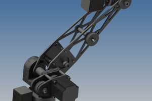
 Andrew Becker
 Maximiliano Palay
I am excited to see this project done !
I would like to use it with the hand I am making, also low cost like this.
What is the expected payload? I need at least 3kg to be safe with manipulations.