Close
0%
0%

RoboDog

Cheap 3D-printed robot dog: 14-DOF ESP32 quadruped with wobbly first steps, jittery servos and lots of room for hacks at around ~100€.

Similar projects worth following
This is my DIY robot dog built mostly to see how far I can push a cheap setup before everything falls apart. The goal was simple: a 3D-printed quadruped that actually walks, stays (roughly) in one piece and costs around 100€ in parts, without hiding any “oh and also a 300€ toolkit” in the fine

The dog has 14 degrees of freedom: 3 servos per leg (12 total for the legs) plus a 2-axis camera head. It’s driven by a Raspberry Pi Zero 2 W and a bunch of hobby servos, with a fully 3D-printed frame. I did all the design, wiring and code myself, so most of it is intentionally simple and hackable rather than polished.

The code is still messy and there’s a long list of possible upgrades: nicer gaits, better stability, maybe ArUco marker navigation and more vision-based stuff. I don’t plan to actively work on it in the near future, so consider it a working shareable experiment, rather than a fully finished prioduct

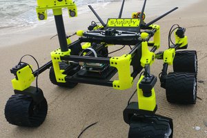
This is my DIY dog made only from parts you can simply buy, no custom PCB, nothing exotic or too over-engineered. The idea was to have a 3D printed quadruped that actually walks, does not immediately disintegrate, and stays around 100€ in parts. The brain is a Raspberry Pi Zero 2 W running Python. Power comes from two 18650 cells, each with its own step-up converter: one for the Pi, one for the PCA9685 and all the servos. Grounds are connected, but power is split so the Pi does not collapse into some catastrophic brownout every time the dog moves.

The dog has 14 DOF: 3 joints per leg and 2 for the camera head. Most joints use MG90S metal gear servos, with a few TS90MD mixed in, and small 9 g Miuzei servos for the camera. For vision there is a Freenove 120° 8 MP camera, so later I can play with ArUco markers and other slightly more sophisticated experiments.

All parts I modeled in FreeCAD and printed on an Anycubic Kobra 3. Right now the dog can walk in any direction, rotate in place, and the speed is adjustable. The code is still messy and a bit chaotic, but good enough to share and use as a small experimental platform. The code itself will be published a bit later, after I clean it up at least a little, remove redundant stuff and make sure there is no data I would prefer not to expose.

  • Leg day

    Stanislav Britanishskiian hour ago 0 comments

    So, let me make today a leg day.

    Designing and programming the legs was the main part of this whole project, everything else was a baby's play compared to it.

    So for the legs I would require 3 servos, one of them to move the leg sideways, one for the ankle and one for the shin. And for the code I would have a class with a few functions, the main one of them would take the desired position of the leg tip in XYZ and calculate the angles for each of the servos.

    There was a lot of tinkering around with the PCA9685, that is the servo controller, somehow the data that I was finding didn't match what was happening, the PWM cycle setting turned out to be a huge headache, after the PCA9685 finally gave up I ended up with some weird function for cycle and angle setting.

    My initial idea was to take 180 degree hobby servos and make a gear ratio of 1:2 to decrease the load on the servo but also decreasing the moving range, somehow I thought that the servos would be too weak to carry all the weight, considering that in the beginning I was planning on using 4 18650 batteries in series with a step-down converter.

    That was my first time designing gear with FreeCAD, and, god, did it take a lot of time to figure all the details, make it perfectly fit the servos without any screws, distances between the gears and overall work, many iterations of printing, reprinting, throwing the failed versions again and again. And finally I got this


    After the first leg version was physically complete I had to implement the calculations for the servos. I did a lot of googling, conversations with ChatGPT, they both were continuously telling me something about Inverse Kinematics, went in there, checked out a few tutorials on YouTube, turns out to be some magical transformations from linear algebra, and that was never my best understood subject. At the moment I was in another one of my idiotic relationships and I was constantly accused of wasting too much of my time with everything but her, so the project got frozen for about half a year that was taken by suffering a bit more, heavy drinking and stopping the heavy drinking.

    Finally half a year later I got back to the project and it turned out to be a very simple problem that can be solved with pen and paper in half an hour using only basic geometry.

    The leg design turned out to be very impractical, all these gear connections would constantly fall apart, the leg couldn't survive any side load, so I had to go back to FreeCAD and redesign it all once again, after tons of wasted plastic I ended up with this

    This one I still kinda like in terms of the looks, but it was a bit too long, so again it was pretty hard for the dog actually to have enough torque, also due to many parts it wasn't very stable or easy to assemble, and the leg pieces were connected to servo horns directly, so the parts could kinda easily slide over on the horn, which meant that the angle could very quickly offset itself.

    So here we go redesigning again. Now I wanted to use the original servo connector and somehow connect to it, that would give me a lot more stable construction, in a week or two I got to this design and it was already pretty good.


    This was already pretty nice, but it was somewhat too long and the dog kept falling, so after a bit of redesigning I got to this

    and here is one more video with a fall

    This is the final version, the body of the dog was still a bit changed later on, but legs are still the same

  • Fighting the printer

    Stanislav Britanishskii11/26/2025 at 19:55 0 comments

    For my first private printer I chose Kobra 3. There were a few reasons. I was used to Prusa printers at the moment, but they were a bit too expensive for me, and I thought that Anycubic Slicer would be easy for me to master as it is a fork of PrusaSlicer. The announced speed of the Kobra sounded amazing and the print quality wasn’t that super important for me at that moment. And the main reason was that the Kobra was on sale then.

    The very first problem I encountered was that the filament was sent in a different shipment and arrived a couple of weeks later than the printer. So in the beginning I only had the test piece several meters long, yet that was enough to print one of the provided samples. Speed was really amazing compared to Prusa Minis, which I was used to.

    The second problem was that I didn’t do enough research and didn’t even think that this could be a case. It turned out that Anycubic Slicer doesn’t run on Linux and I don’t have any Windows devices. The internet told me that no slicers at the moment supported my printer. So I had to iterate through several different slicers, and just as expected they didn’t have the profile for the Kobra. Finally I stopped with Orca Slicer and some custom profile I found online and have been using it ever since.

    It took me a bit of tinkering around to get everything to work properly, for example Prusas are way more precise. If I had to make two parts fit each other I didn’t have to add any margin, yet with Kobra it turned out I had to give at least 0.2 mm margin for rigid connectors and something about 0.5 mm, and that did take some trial and error to find out.

    After all of this was figured out the printer was running smoothly for 7 months or so without any repairs or major changes in settings. That is until I decided to change support type in the slicer from standard trees to manual tree, some kind of trees where you explicitly choose areas to be supported. That was a long print, one of the first versions of the dog body and a few parts of legs, for around 6 hours, so I just ran it overnight. In the morning I came to check on the print and saw something weird: after half a centimeter the layers seemed to be all moved a centimeter to the side and there was a big hole on the side as if the nozzle melted into it like an icebreaker.

    The body I threw in the trash and decided to print the leg pieces one by one, they worked out okayish, but the body with supports did exactly the same thing again, also all the prints were a bit offset from where I expected them to be on the print bed. After some investigation it turned out that the nozzle was severely bent, so much that I was surprised that it could print anything at all.

    I bought a new nozzle, printed some legs and other pieces, everything was all right, until I tried to reprint that body with supports, obviously it got bent again.

    After buying a new nozzle and printing the same piece with different supports I got a confirmation that the issue was in the generated G-code and was somehow connected to that support setting.

    Other than all the stuff listed at the top, there weren’t any major difficulties with the printer; it was working pretty well, it just turned out to be a bit better to run it on the floor, as all the tables I have are too shaky.

    This isn’t the end of my sufferings, but these are all the problems I got from the printer, about the rest of the stuff I will tell in the next logs.

  • Introduction to story logs

    Stanislav Britanishskii11/25/2025 at 21:03 0 comments

    I’m very excited to share my first solo robotics project and tell the story of how it was created.

    The project is more or less finished by the time I’m writing this, so the logs won’t be real updates, but rather the journey of the creation. I believe it will take me several log posts to tell it completely. Sometimes I probably won’t follow the exact timeline, as memory was never my strong suit. Hopefully reading all of this will be worth your while. English is not my first language, so I’ll be using chat to correct the mistakes I make, but I will try to avoid that AI-generated text you can see in the description of the project.

    First let me tell a tiny bit about myself. Originally I’m from Moscow, Russia. I moved to Germany a few years ago, because I was a bit afraid for myself in the context of the situation. Unfortunately that meant that I didn’t finish my studies in computer science, and later it turned out to be close to impossible to re-enroll in Germany. After a while I got hired in a small robotics company, mainly doing software, yet due to the extremely small size of the company I was running into all kinds of tasks. That’s how I learned how to use FreeCAD, solder, and handle hardware to some extent.

    Overall, I’ve had the idea of making some kind of robot since I was a kid, yet there were always some reasons to postpone it. That could be lack of knowledge in a topic, lack of time, lack of understanding of how to approach such a project, lack of materials, and so many other reasons. Thanks to the company I got an understanding of what I needed to buy and what I would need to use in terms of hardware. Nevertheless, later it proved to take tons of time figuring out all the details.

    About a year ago I finally made up my mind and bought myself a 3D printer, a cheap soldering iron, a Pi, the first pack of servos, a PCA controller, a few batteries, a charger for them, a step-down converter and probably something else that I don’t remember.

View all 3 project logs

Enjoy this project?

Share

Discussions

Similar Projects

Does this project spark your interest?

Become a member to follow this project and never miss any updates