-
1Step 1
Central axis:
Items needed:
1 - Cilindrical aluminium pipe // 20 mm diameter // lenght: 35 cm // Units: 7
2 - Cilindrical aluminium pipe // 10 mm diameter // lenght: 35 cm // Units: 6
3 - Printed parts // numbers : 1 and 2 (Central base gear and base hold)
Instructions:
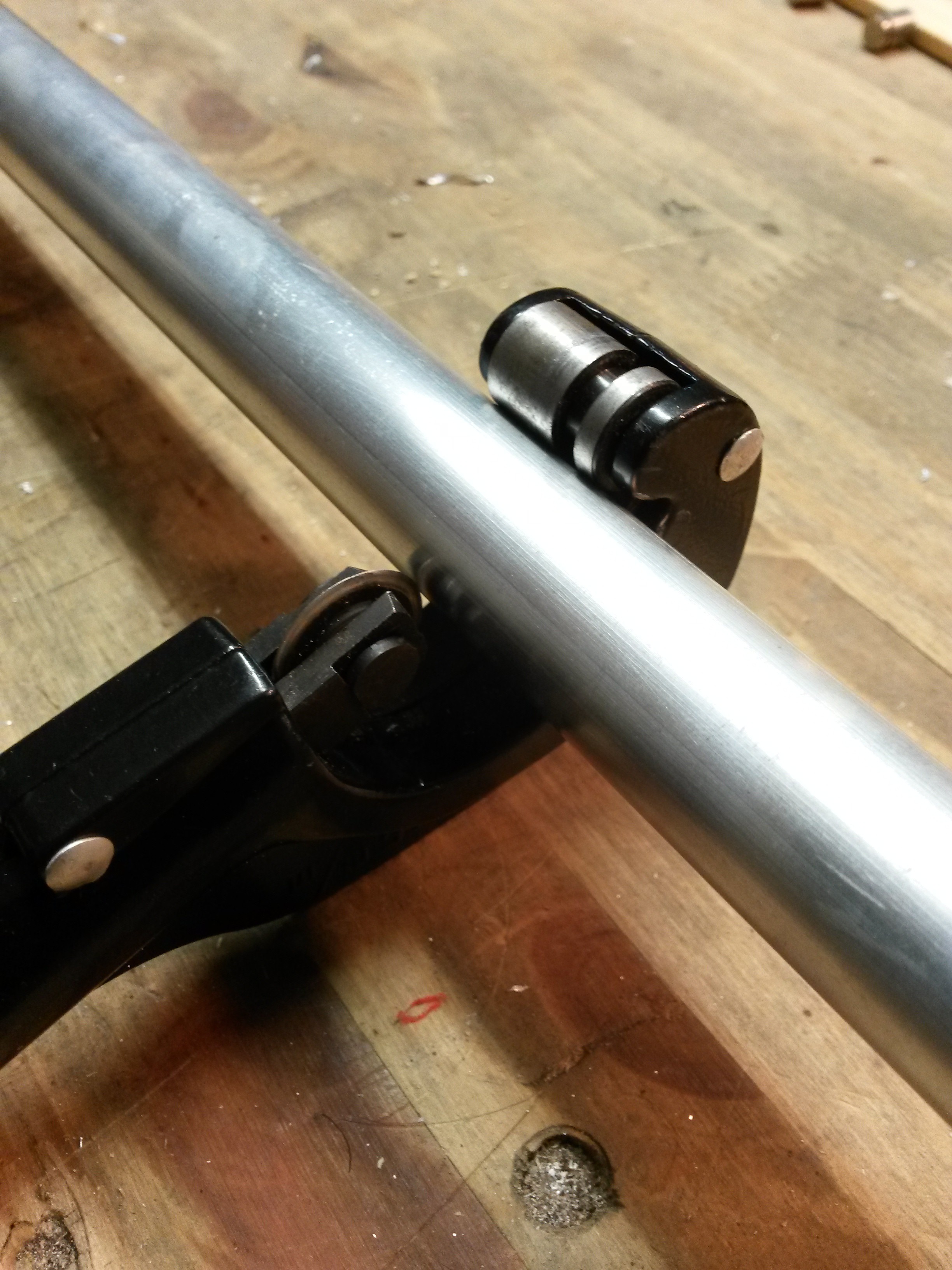
-First you have to cut the pipes to 40 cm, i used a pipecutter like this one:
![pipecutter]()
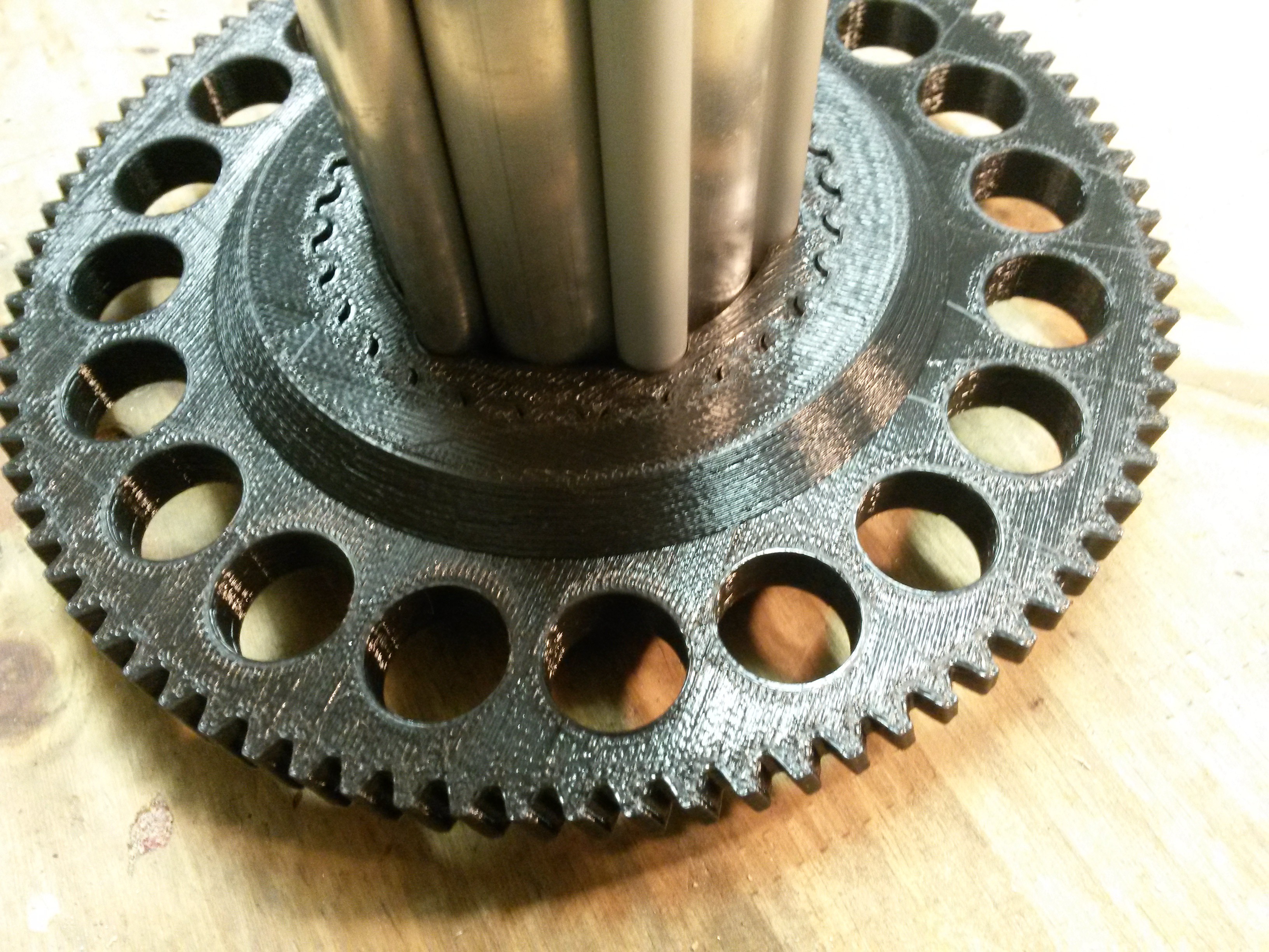
When you have all the pipes, put all together inside the 3D base hold, i put two screw with a few glue to make the joint stronger.
![]()
Joint the central base gear and the hold base just pushing
![]()
-
2Step 2
3D printed cover and holders of central axis
Items needed:
1 - Printed parts // numbers : 3,4,5,6 and 7 (covers and holders of central axis).
2 - Rubber Head Hammer.
Instructions: (important: must put the lazy susan bearings with covers into the axis before other 3D parts)
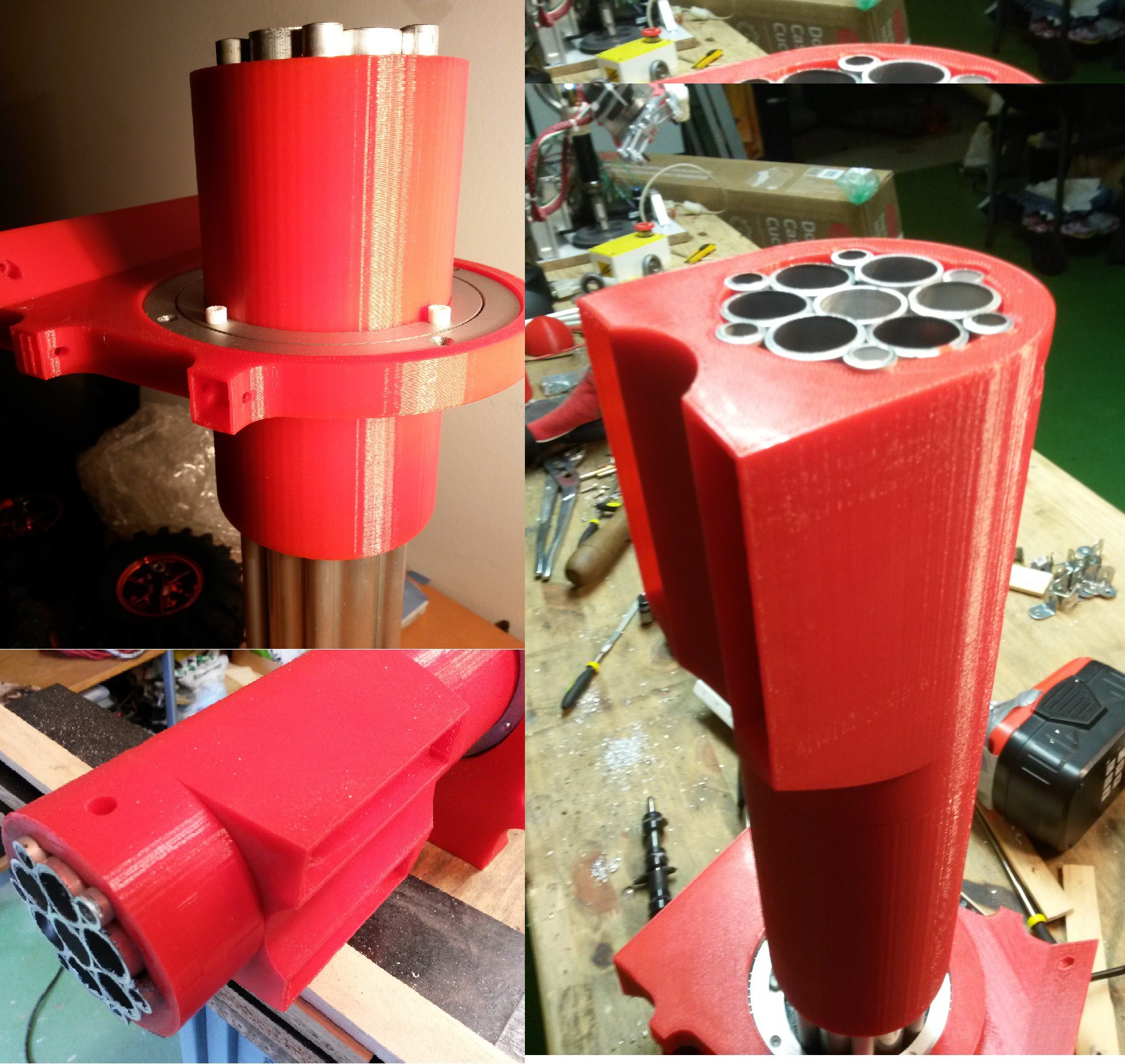
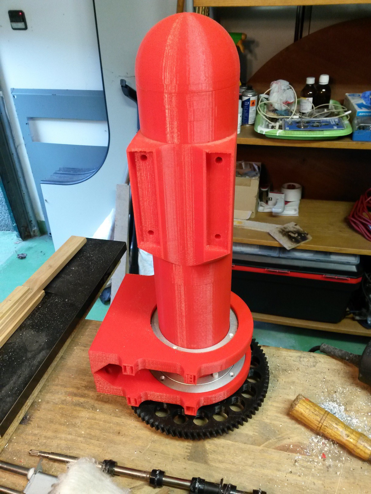
First put lazy susan bearings in their position ( on 3D nº7), then introduce the following 3D parts around the central axis in this order, nº3, lazy susan, nº5 and nº6 like the following images.
See that i put the lazy susan one opposite to the other, because i want one bearing in the highest possible position in the base box.
I used a rubber head hammer to put this 3D parts, you must have caution in order to not break any part, it's a bit dificult to insert the 3D parts, but i made this because it helps to distribute the forces supported by the axis.
So you must have this:![]()
![]()
-
3Step 3
Base
Items needed:
1 - Printed parts // numbers : 8, 9, 10, 11 and 12 (base bearing up and low, motor base holder, base gear, and base joints).
2 - m3 x 10mm and nuts, units: 4
3 - m4 x 30mm and nuts, units: 8
4- m5 x 12mm and nuts, units: 16
5- wood screws, units: 8
6- corner braces for wood screws, units: 4
7- corner braces for m5 screws, units: 4
8- vertical force bearing(on components)
9- 12x10 mm aluminum frame
10- m3 x 25 and nuts, units: 12
11- m4 x 115 mm threaded rod, units: 4
Instructions:
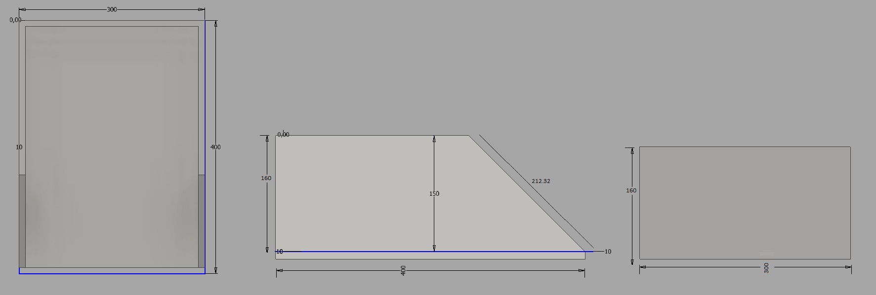
First you must cut the wood with the following dimensions:
I use mdf panel to build this 'box' i selected the 10mm width one, i think it can be hard enough to hold the robotic arm, because I'll go around it with aluminum, but this is the second part of the base.![]()
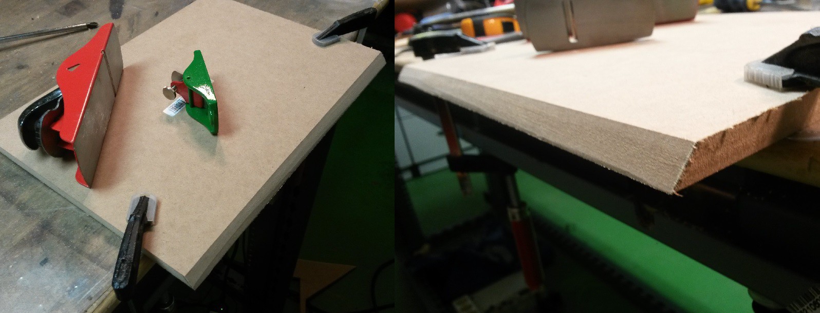
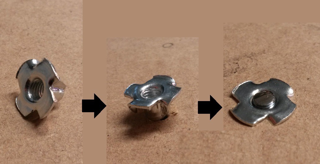
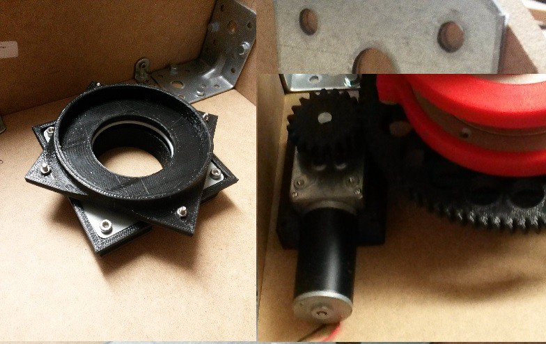
![]() I did the angle handmade, but with a cnc it will be more accuracy. I selected this kind of nuts for the lower part of the base, it is simple to use and seems to have very good result, i put the link where y bought them on components needed. You need 8xm5 and 8xm4.
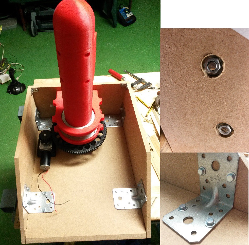
I did the angle handmade, but with a cnc it will be more accuracy. I selected this kind of nuts for the lower part of the base, it is simple to use and seems to have very good result, i put the link where y bought them on components needed. You need 8xm5 and 8xm4.![]() Finally I put the corner braces at the best position, it depends on wich corner you used, but think about of putting the dc source, arduino, motor drives and some extra space to future aplications and select corners with the idea of be hard enought to support all the forces of the robot arm.
Finally I put the corner braces at the best position, it depends on wich corner you used, but think about of putting the dc source, arduino, motor drives and some extra space to future aplications and select corners with the idea of be hard enought to support all the forces of the robot arm.
Now that the base is finished you can screw the motor and the bearing like the following pictures:![]()
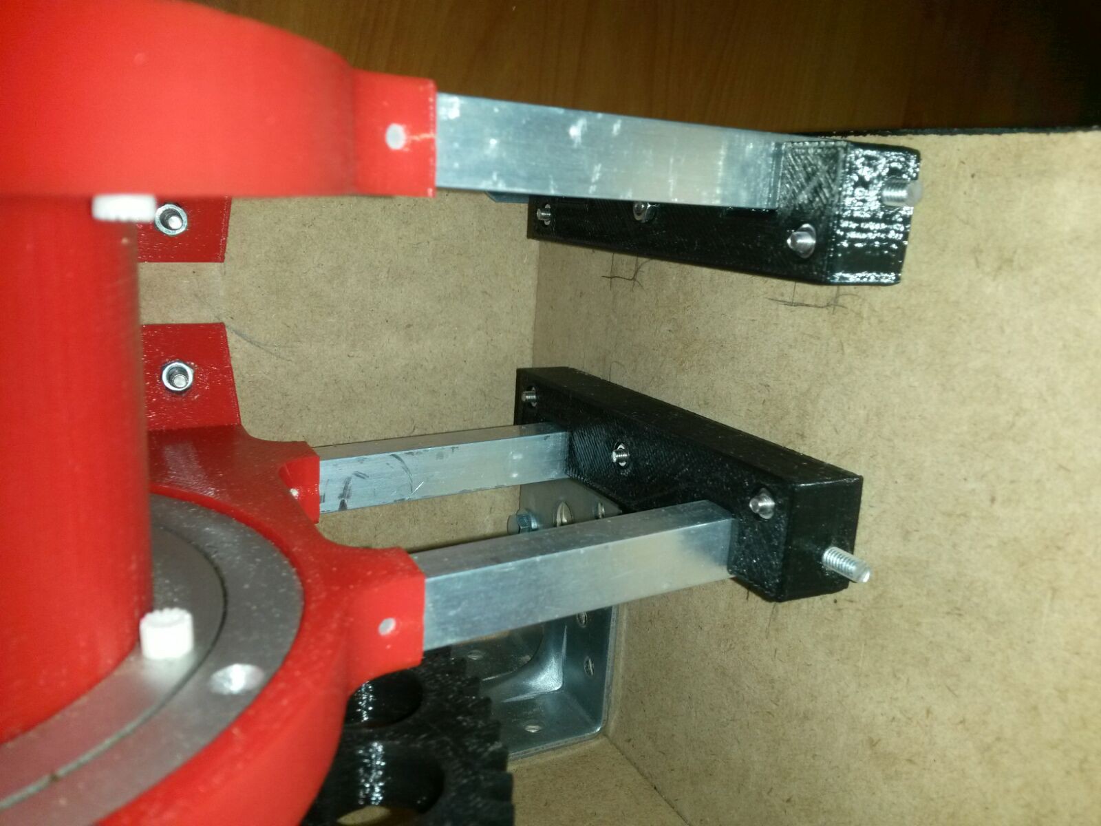
![]() Next you have to cut some 12x10 aluminum frames to hold the lazy susan bearing to the bases's walls, it must be around 85mm each one(8units) but it depends of the positions of the arm(i put it in the middle).
Next you have to cut some 12x10 aluminum frames to hold the lazy susan bearing to the bases's walls, it must be around 85mm each one(8units) but it depends of the positions of the arm(i put it in the middle).Then you must use the base joints(nº 12), put the joint into his positions and make the holes into the wood. I make the holes to be used with M3 screws and a M4 threaded rod.
![]() So you must have something like this:
So you must have something like this:![]()
Now to finish the base, we only need an aluminum platten to make the walls stronger, as fast as i can y upload the last part of the base.
See you soon!
DIMER MKII, Large open robotic arm
An open design robotic arm, made with dc motors, 5 degrees of freedom, can pick up 5 Kg at 1.50 m and with the lowest cost posible
 Antonio Regueira

 So you must have something like this:
Discussions
Become a Hackaday.io Member
Create an account to leave a comment. Already have an account? Log In.