-
Shoulder movement
03/21/2017 at 12:43 • 0 commentsI select dc motor beacuse are cheap and i can control it well with a closed loop control sistem, with optical encoders.
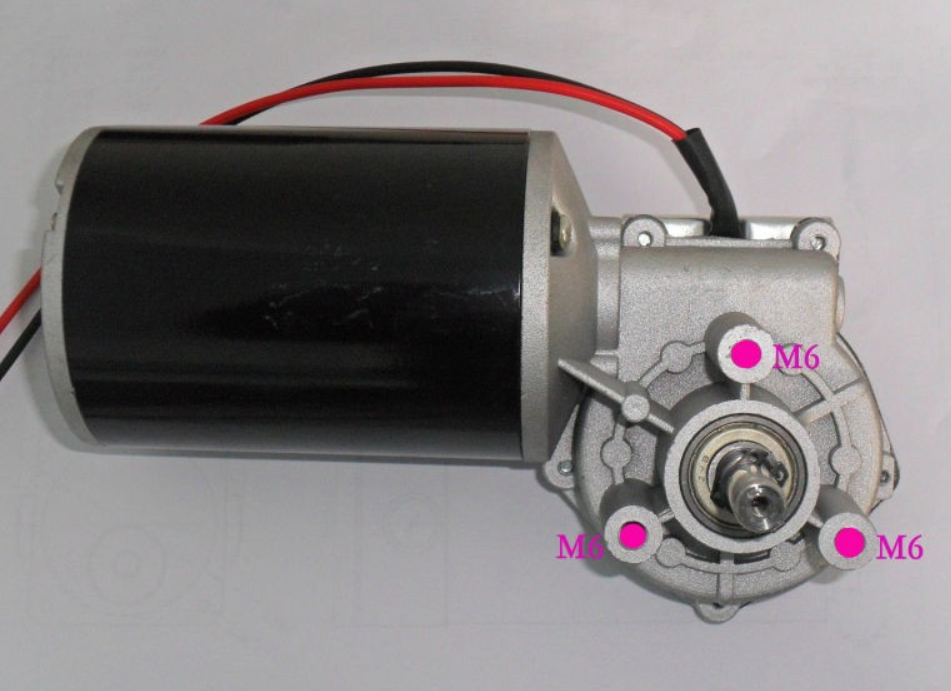
I look for a lot of motors and finally find this one:
This a 24 V DC motor 40 RPM and 120 W, with a nominal torque of 25 N*m, i built a gear reducer to 4 RPM, as i saw in mechanical engineering books the torque is proportional to velocity, so 40/4=10 and 10*25=250 N*m. 1 Kg*m is equal to 9.8N*m so 250/9.8=25.5Kg*m. This is a lot of torque!
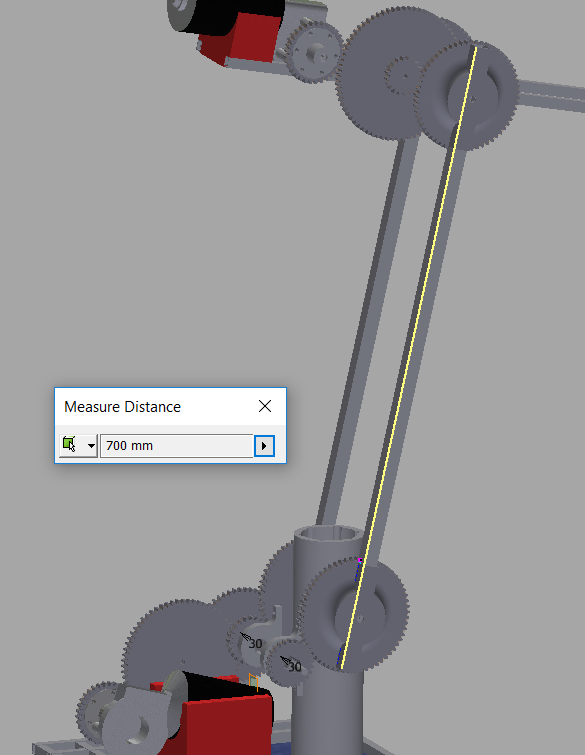
 The part form the shoulder to the elbow is 70 cm.
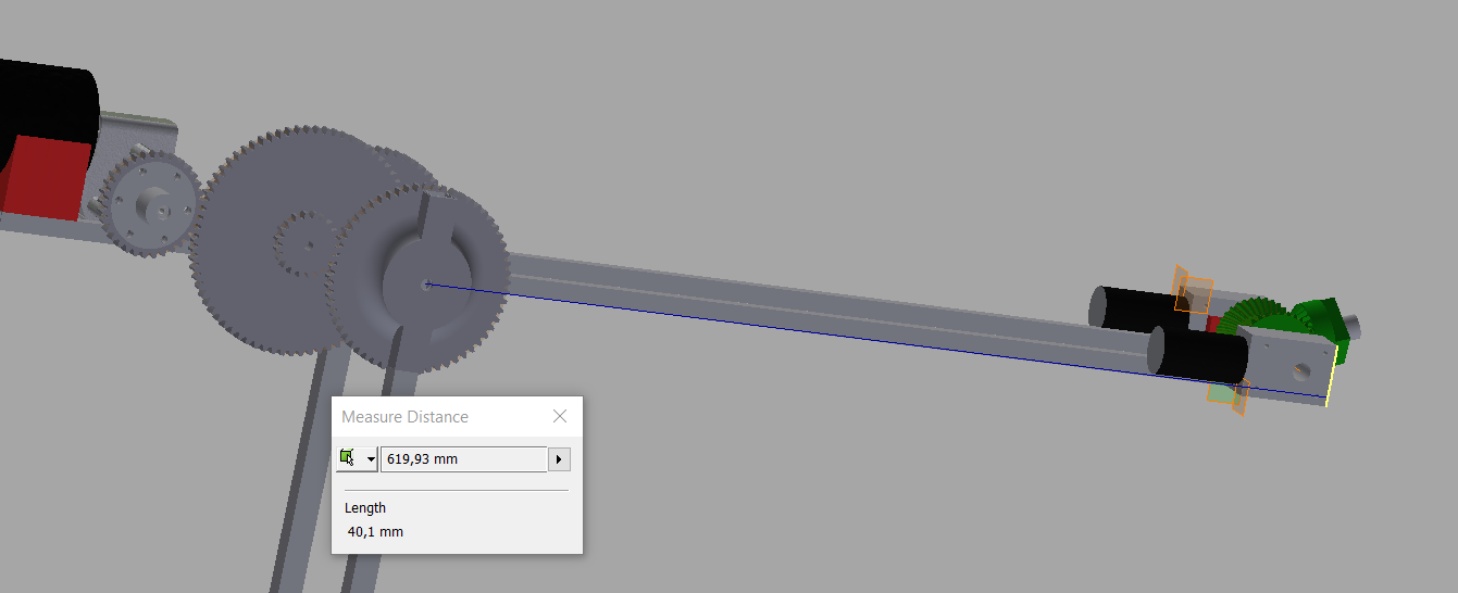
This other part is about 62 cm plus the gripper(i didn't design it yet but more or less it will have about 20 cm).
 So i have 70+62+20=152cm. This is the maximus action radio of my robot arm.
Then, if i have 25.5 Kg*m/1.5m=17Kg, i have to subtract the weight of the elbow motor and the wrist but i think i can pick up 5 Kg at the max lenght posible.
-
Horizontal movement
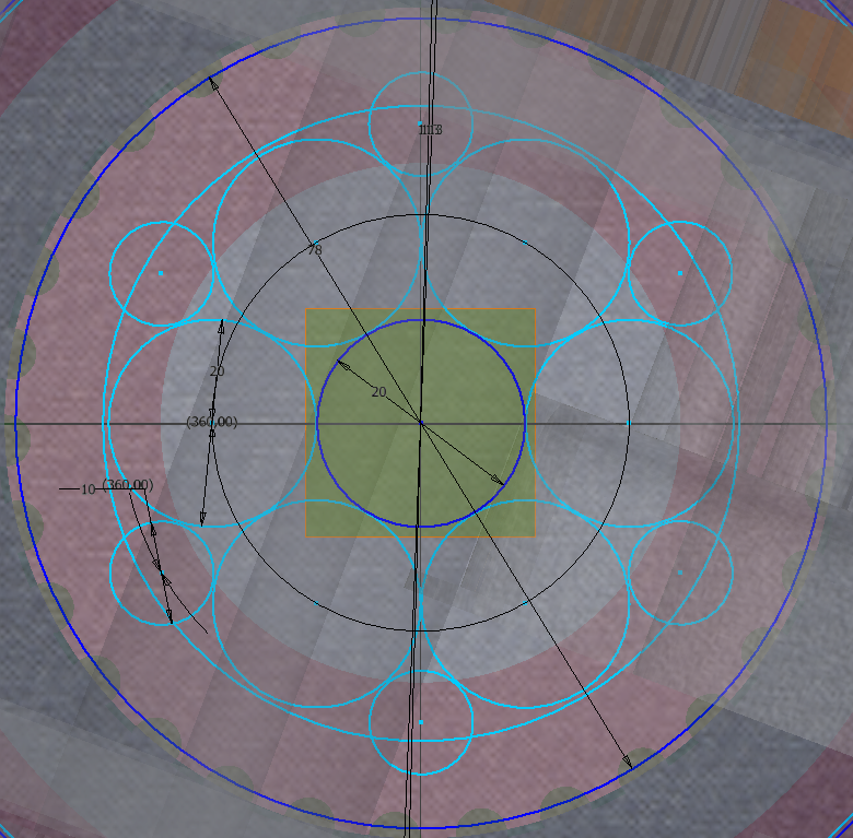
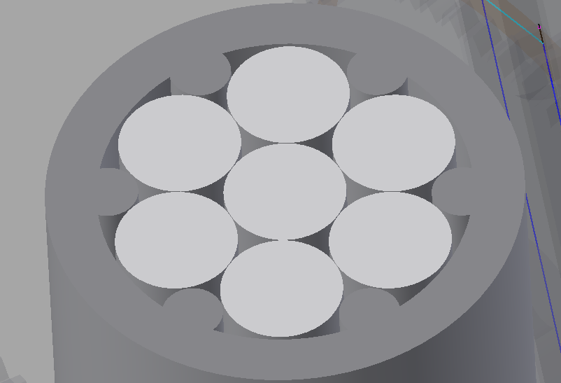
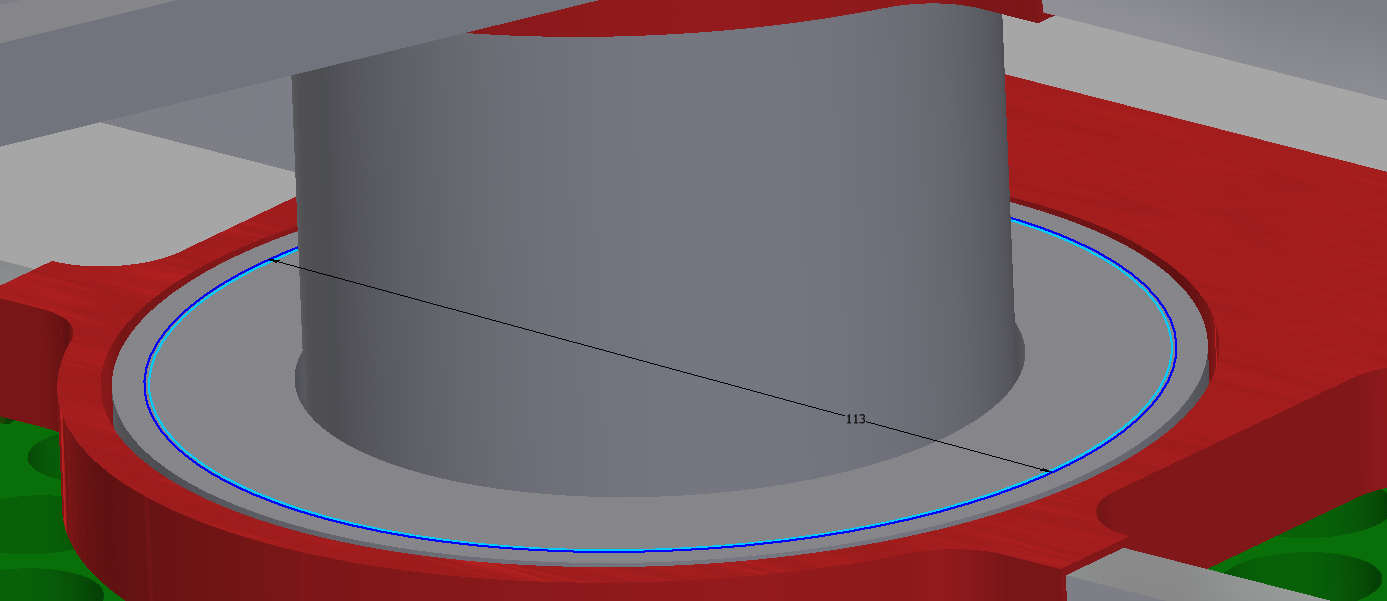
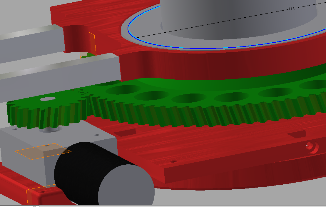
03/21/2017 at 12:08 • 0 commentsThe structure will be mostly in aluminium, with square profiles, i studied the capabilities of this kind of structure and it can work fine. i solve the problem with the horizontal movement with a set of cilindrical aluminium profiles, exactly with 7 of 20 mm of diameter and 6 of 10 mm, i choosed this solution because it is cheaper than a large cilindrical profile and has much more strenght, this set will be joined with 3d printed part and holded by 3 bearings, 2 lazy susan with an 80mm diameter and 1 to support the vertical force, in those 3 images you can see the system.
The first one, is a 2d sketch, the possition of the profiles. The blue circle marks the limit of the 3d cover.
The second one, you can see the cover, with 7 circular profiles of 20 mm and 6 of 10 mm, all the profiles will be empty so i will pass alt he cables to the rest of the arm by the central one.
In this image you can see the central column with a bearing, i choose a lazy susan with 80 mm of diameter, and it will be holded to the structure by a 3d piece(the red one) and some square profiles of 16 mm.
This is the motor of the horizontal movement, with 3d printed gears, under the central column there is an encoder so i can know the position.
DIMER MKII, Large open robotic arm
An open design robotic arm, made with dc motors, 5 degrees of freedom, can pick up 5 Kg at 1.50 m and with the lowest cost posible
 Antonio Regueira