 loudaslife
-
Image Processing
02/19/2026 at 01:05 • 0 commentsNow that Micro-Manager has provided me with several hundred individual frames, rather than the single composited image I would've liked, I have to process them myself. I'm not aware of any software that does both focus stacking and image stitching decently. (Actually, I never even found software that does either step as well as I would like.) That means we'll have to look at the two steps separately. I don't even remember half of the tools I tried, so we'll just look at the least terrible solutions I found for both.
The question is, which operation do we perform first?
Advantages of performing image stitching first:
- Focus stacking tends to produce blurring around the edges of the image. If we do image stitching first, this edge blurring would only be at the edges of the very final image, where it can easily be cropped out.
- Counterpoint: If you leave enough overlap between images, you can just crop this out of each intermediate image before stitching. And even if you don't bother to crop it, the interpolation between adjacent images during stitching largely ignores the very edges, so it usually doesn't matter.
Advantages of performing focus stacking first:
- The image stitching programs I've tried can struggle to match up edges even on perfectly sharp images. It's not even worth trying to stitch together an image where 80% of the frames are completely out of focus.
- Focus stacking is more likely to add blurry artifacts throughout the image as the number of frames in the stack increases. If you do focus stacking first, you have the opportunity to manually delete all the frames where no part of the image is in focus. This significantly reduces the severity of artifacts in flatter areas that only span a few frames in height.
![]()
![]()
(Click images to view full size)
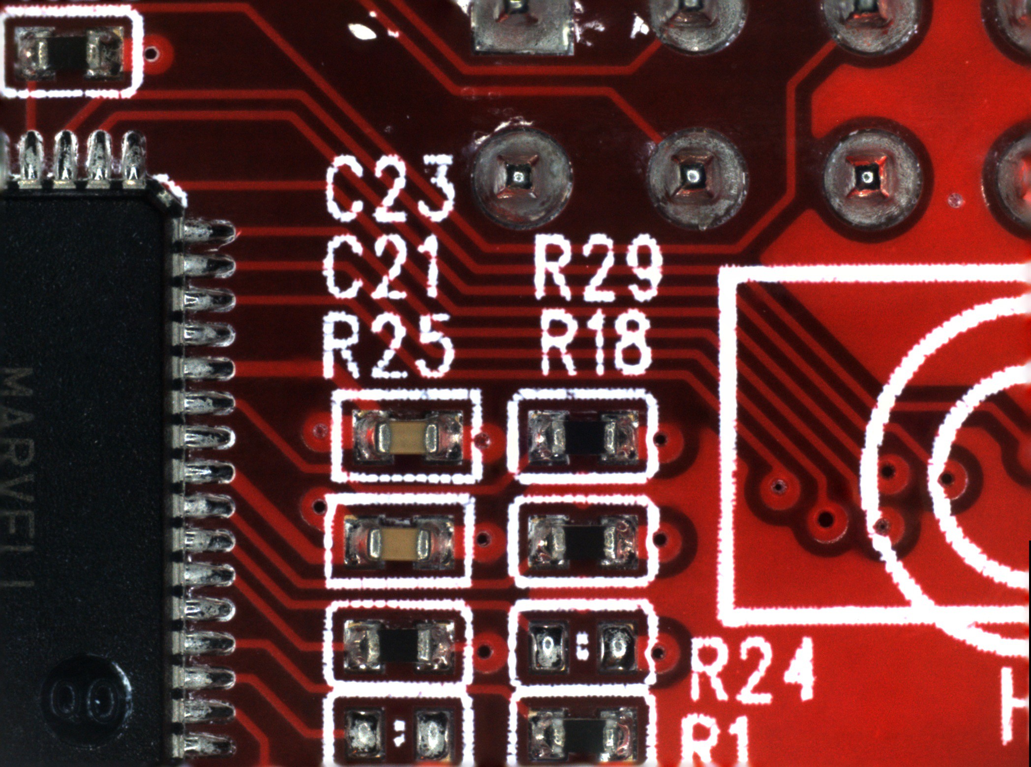
The first image (on the left) is focus stacked from all nine frames acquired in this area. There are strange blurry artifacts in a few of the traces adjacent to the high contrast of the silkscreen. You can also see the blurring around the edges of the image that I mentioned earlier. The second image (on the right) only uses the lowest three frames, which produces a cleaner image.
So, now that we've established that focus stacking is the first task:
Focus Stacking - Photoshop
Photoshop was the least terrible of the many tools I tried for this. My workflow ended up as follows:
- Go to "File > Scripts > Load Files into Stack..." then select all the images files to be stacked. This loads each file as its own layer.
- Go through the layers and delete the ones where nothing is in focus.
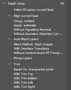
- Select all the layers and use the auto-align and auto-blend tools to do the actual focus stacking. Then merge the image back to one layer and trim the away the transparent edges that occasionally pop up. I made a macro to do all of this with one key press. It looks like this:
![]()
- Export the stacked image and move on to the next. Make sure the file names stay in sequential order so that the image stitching software can process them.
Image Stitching - Microsoft Image Composite Editor
Surprisingly, the least terrible tool I've found for this is a discontinued piece of freeware from Microsoft.
![]()
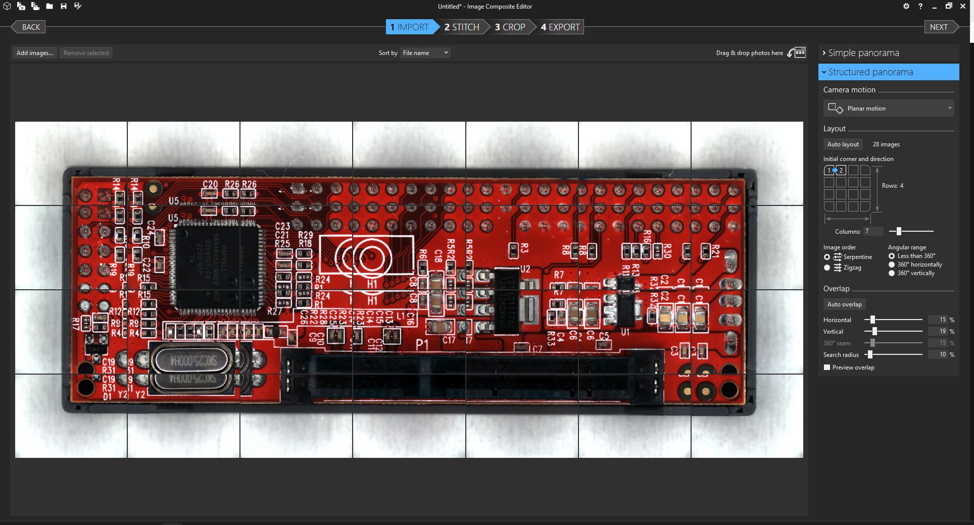
The process is quite straightforward. You'll want to select "Structured panorama" with the "Planar motion" option in order to give the software the fewest opportunities to screw things up. If the "auto layout" button doesn't come up with the correct tiling, you'll also have to also adjust the layout options until the images appear in the correct order.
I'm not sure if fine-tuning the overlap settings actually changes very much, but I usually do it anyway until the preview looks as good as I can get it.
Everything after that is self-explanatory. Just make sure you examine the final image carefully before relying on it for anything. I've had weird distortions pop up for no reason. I still don't trust the output of this whole process well enough to use as anything but a reference.
![]()
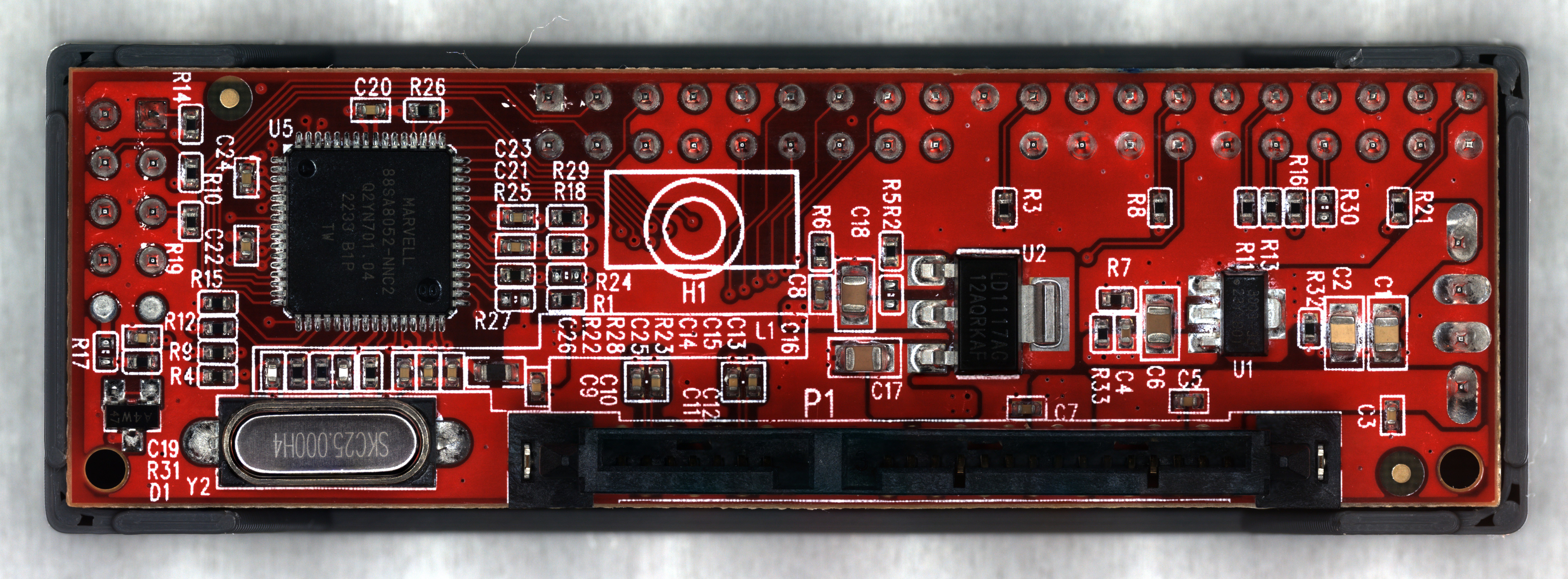
After all that, I'm reasonably happy with the final result. The full image is 48 megapixels, so the picture above is scaled way down. It's not phenomenal quality, but good enough for the reverse engineering work I plan to do.
- Focus stacking tends to produce blurring around the edges of the image. If we do image stitching first, this edge blurring would only be at the edges of the very final image, where it can easily be cropped out.
-
Firmware and Micro-Manager
02/18/2026 at 12:44 • 0 commentsMarlin
I chose Marlin for the
printermicroscope stage firmware, mostly because I had a little bit of experience configuring and compiling it in the past. The configuration process wasn't much different than setting it up for a regular printer. If you put "#define EXTRUDERS 0" and comment out anything related to heaters or the E axis, it'll happily run without a hotend or heated bed.Micro-Manager's RepRap support is not particularly customizable, so there are a few changes on the firmware side that make things easier. It always issues movement commands in absolute coordinates, and it will always start from coordinates X0 Y0 Z0. (There might be an option to override this, but I couldn't find it.) So the coordinate system origin should ideally be in both a convenient and safe position, namely the center of the bed at the top of the Z travel. The "BED_CENTER_AT_0_0" option is essential for this. I would also recommend "NO_MOTION_BEFORE_HOMING" to further ensure you don't accidentally crush any samples into the bed.
I'll upload my config.h file to the project page, just in case somebody finds it useful as a reference.
There are a few Marlin bugs I never figured out, like the fact that default movement speeds and sensorless homing thresholds would change themselves to unknown values (not the ones in the config) after power cycling. Disabling EEPROM didn't help. So I have to send an M502 after every power on to load the correct values, which is fine because I already had to manually home the thing after every power on anyway. I never found any option to send a home command from within Micro-Manager, so the startup process involves opening Pronterface and sending M502, G28, and optionally G34 commands before ever launching Micro-Manager.
Micro-Manager
I felt pretty good about how this entire project was going, right up until I had to dive into Micro-Manager. Oh boy do I hate interacting with this software. All of my hardware and firmware work so far was done under the assumption that Micro-Manager would be, you know, usable. Because to my knowledge, there are no free alternatives that do even half the things I require.
The first problem is that no matter what I do, I can never get it to save all of my configuration info. MOST of it will save to a .cfg file and load up at the next launch perfectly fine. But for whatever reason, it insists that my camera should always start in black and white mode with automatic gain, and the Y axis stage movement is always inverted until I manually open the settings and fix it. So that's another set of configuration steps every time I want to use this thing, on top of manually homing the stage beforehand.
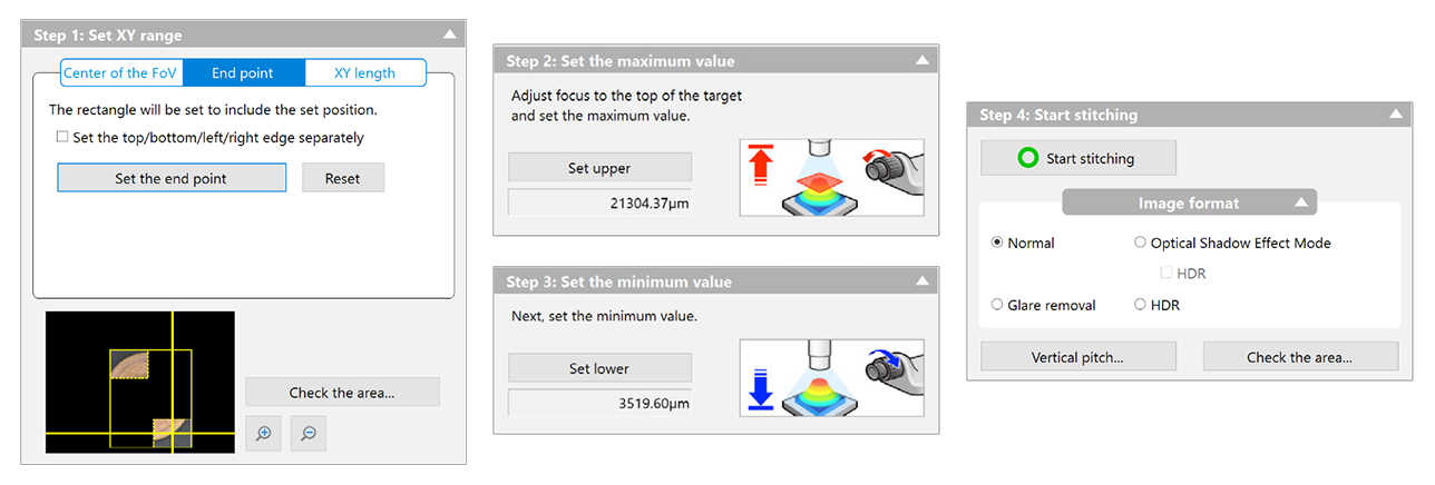
Now, finally, everything is configured, more or less. The microscope is ready to use. I'd like to do what Keyence would call "3D Image Stitching". In this mode, the user specifies an area to image, and the software automatically controls the stage to scan over the area and capture images at a variety of heights. It then composites all of them together into a single high resolution image of the entire area, with surfaces of differing elevations all appearing perfectly in focus. Let's look at what setting this up would be like in Keyence's proprietary software.
![]()
It's a fairly simple 4-step dialogue box, where the user specifies the area to be imaged, the elevations, and a few optional but intuitive settings to tweak. There's nothing to say here other than "it just works." After clicking start and waiting for the microscope to do its thing, the user is presented with an image and the option to save it to disk.
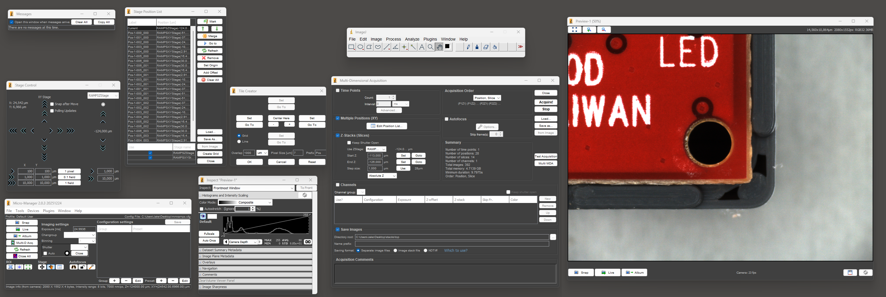
Now let's attempt to do the same thing in Micro-Manager.
![]()
The first step is to open and arrange the nine required windows so that you can see everything. Once you've recovered from the visual horror of this UI and done the whole process a number of times, setting up a "multi-dimensional acquisition" isn't THAT bad. It's nowhere near as pleasant as Keyence's software, but it probably takes 2-3x longer at worst, which is actually somewhat tolerable.
There's a plugin called Micro-Magellan that seems like it might make the process easier, but I could never get it to function in any sense. It would completely lock up without giving any errors or log messages as soon as I tried to capture more than a single frame at a time.
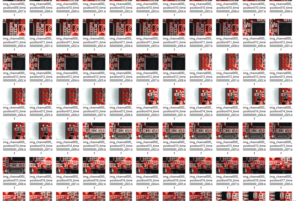
Anyway, once you've actually set up the acquisition and the microscope has finished taking all the images, that's where any illusion of this being an easy process ends. Where Keyence offers you a single JPG or TIF file to save, this is what Micro-Manager gives you:
![]()
As far as I can tell, there's no actual focus stacking or image stitching in Micro-Manager. Once the individual frames are acquired, everything else is up to the user. Great.
-
Hardware
02/18/2026 at 08:02 • 0 commentsMechanical
To start with, I didn't actually have a spare 3D printer lying around that would be suitable. I did, however, have the frame leftover from a Prusa MK4S to CORE One conversion, along with most of the components salvaged from an old Anet A8 and an MP Mini Delta. The final product is mostly based on Prusa MK3S+ design files (since I didn't have the 10mm rods on hand for a MK4 design), with the rest of the printed parts being modified or designed from scratch to fit the components I had on hand. None of the controller boards I had were modern enough to support sensorless homing, and I didn't want to mess with limit switches, so I bought a BTT SKR Mini E3 V2 on sale for cheap.
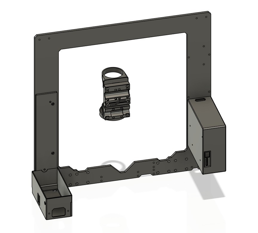
The entire X carriage assembly was redesigned from scratch to hold the optical components. I also had to make new housings for the PSU and controller board, since neither of those were ever meant to go on a Prusa frame. A few miscellaneous extra bits were required, like spacers to limit the X-axis travel so that the ring light wouldn't collide with the frame.
![]()
I don't think any of the printed parts I designed for this will be useful to anyone, but I'll upload them to the project page just in case. Everything was printed from colorFabb XT-CF20, mostly because it was lying around, but I also really love the smooth satin finish it gives.
Optics
I spent a lot of time agonizing over this, with questions like how much to spend on the lens vs the camera. I probably didn't make the ideal choice in the end, but it works well enough for my purposes right now.
![]() I picked the lens first, and after a lot of searching I settled on a cheap unbranded version of a ToupTek TZM0756. At least, I'm assuming what I purchased came from the same factory as the ToupTek ones. It came with zero branding, but seems absolutely identical, and I don't think the budget microscope lens industry is cutthroat enough for someone to be making perfect counterfeits of a brand like ToupTek. Anyway, this was about the cheapest option I found (within the magnification range I wanted) that actually had detailed documentation and specifications available.
I picked the lens first, and after a lot of searching I settled on a cheap unbranded version of a ToupTek TZM0756. At least, I'm assuming what I purchased came from the same factory as the ToupTek ones. It came with zero branding, but seems absolutely identical, and I don't think the budget microscope lens industry is cutthroat enough for someone to be making perfect counterfeits of a brand like ToupTek. Anyway, this was about the cheapest option I found (within the magnification range I wanted) that actually had detailed documentation and specifications available.
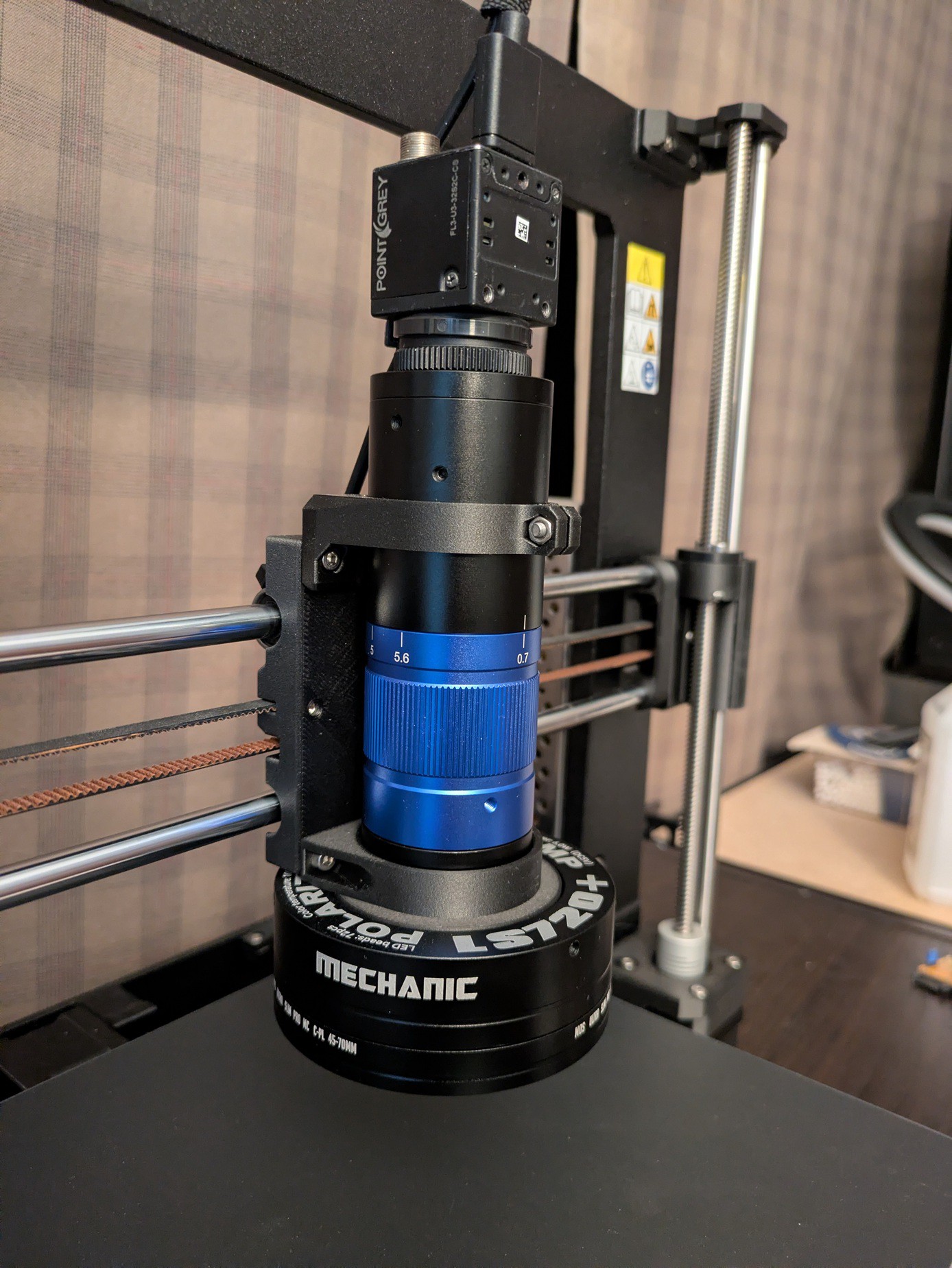
The camera came next, and I ended up buying a used Flea 3 (FL3-U3-32S2C-CS) from Teledyne (formerly FLIR, and formerly formerly Point Grey Research). They still offer firmware updates and support on their website despite this product being two corporate acquisitions old, which is nice. Beyond picking something with a sensor size and mounting thread compatible with the lens, my main criteria for the camera was software support and USB 3. There's already direct software support for this family of cameras in Micro-Manager, which makes things relatively simple.
USB 3 was important to me because you can't stream uncompressed high-res video over USB 2 with a frame rate acceptable for live viewing. Sure, it might theoretically be possible for the software to preview at a lower resolution (or with compression) and then automatically switch to the full uncompressed resolution for image acquisition. But I knew the software side of this was going to be a bigger headache than the hardware, and dynamically changing camera modes introduces too many potential problems. That's also why the "bottom" of the camera is facing the front of the microscope. It would look nicer and the cable management would be slightly neater if I rotated it 180°, but rotating the image back in software is more of a pain than you would think.
The actual resolution of the camera sensor wasn't a huge factor in my selection, because the resolution for most cameras I looked at was well beyond the diffraction limit for the lens itself (assuming my math was correct, which is a big assumption.) For anyone interested, there are various guides and calculators online for doing the math and figuring out what sensor resolution you need to get the most out of a given lens.
The last component was the light source. I would've liked to have both coaxial and ring light modes, just like the microscopes I'm familiar with, but that gets complicated and expensive fast. I settled on a cheap polarized ring light designed for low magnification stereo microscopes. There are lots of these, but I chose a Mechanic LS720+ after reading this excellent review from Pedro J. Aphalo. To be clear, the review didn't suggest that this model of light was particularly exceptional, but it answered almost every question I had about it, and I figured I could put up with the limitations described. The relatively low frequency PWM dimming makes it pointless to use at anything below maximum brightness in my setup, which is neither surprising nor problematic. I've rarely had a reason to turn the illumination below max on any digital microscope I've used. It's far better to reduce the gain on the camera to get an image with the least noise possible.
Motorized Microscope from a 3D Printer
A low cost RepRap-based computer-controlled microscope

 I picked the lens first, and after a lot of searching I settled on a cheap unbranded version of a