Arnov Sharma
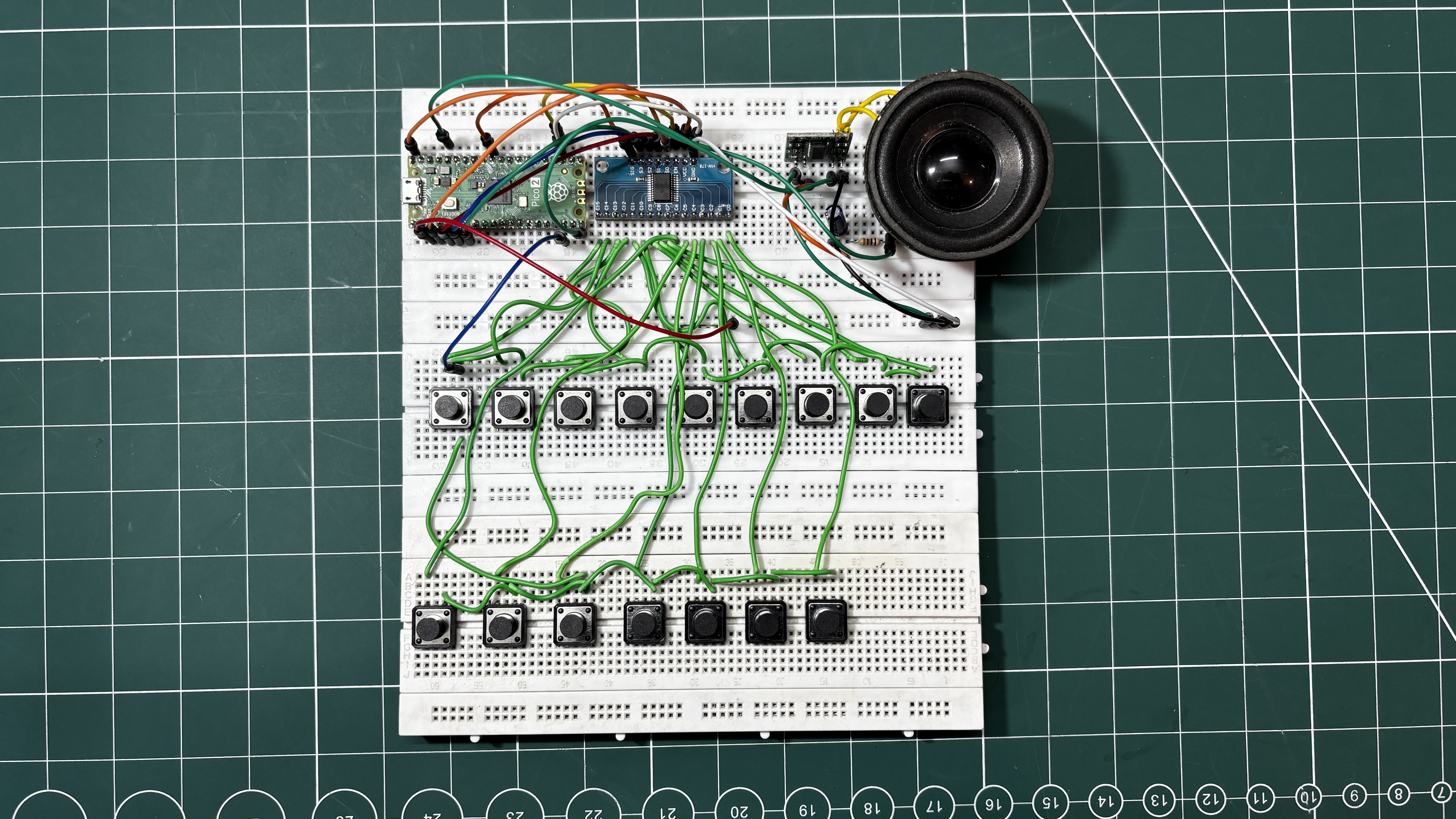
The project was developed in two phases. The first phase was a temporary breadboard setup, where the entire synth circuit was assembled using three interconnected breadboards. This allowed the core functionality of the synthesizer to be prototyped and tested quickly.
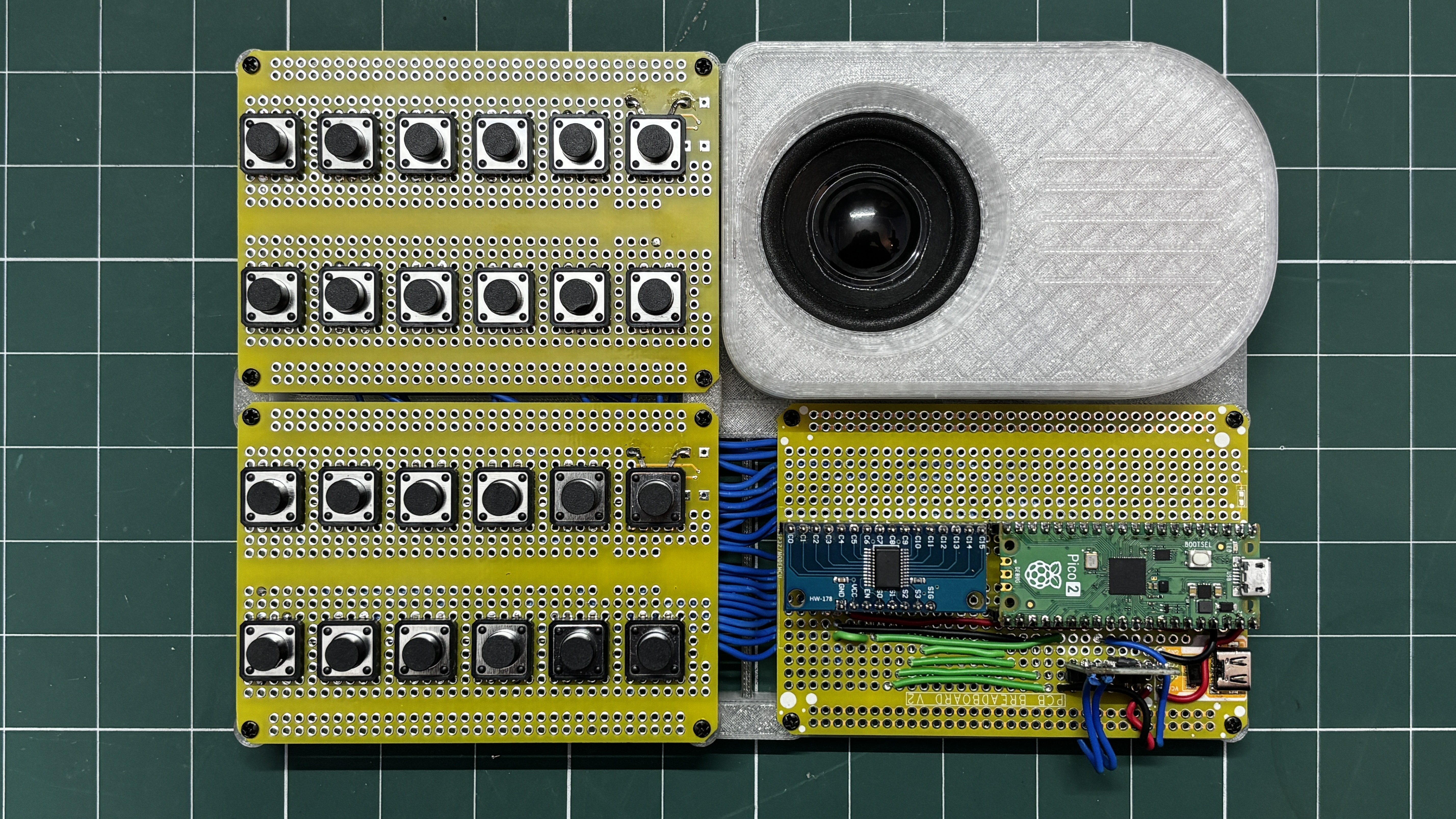
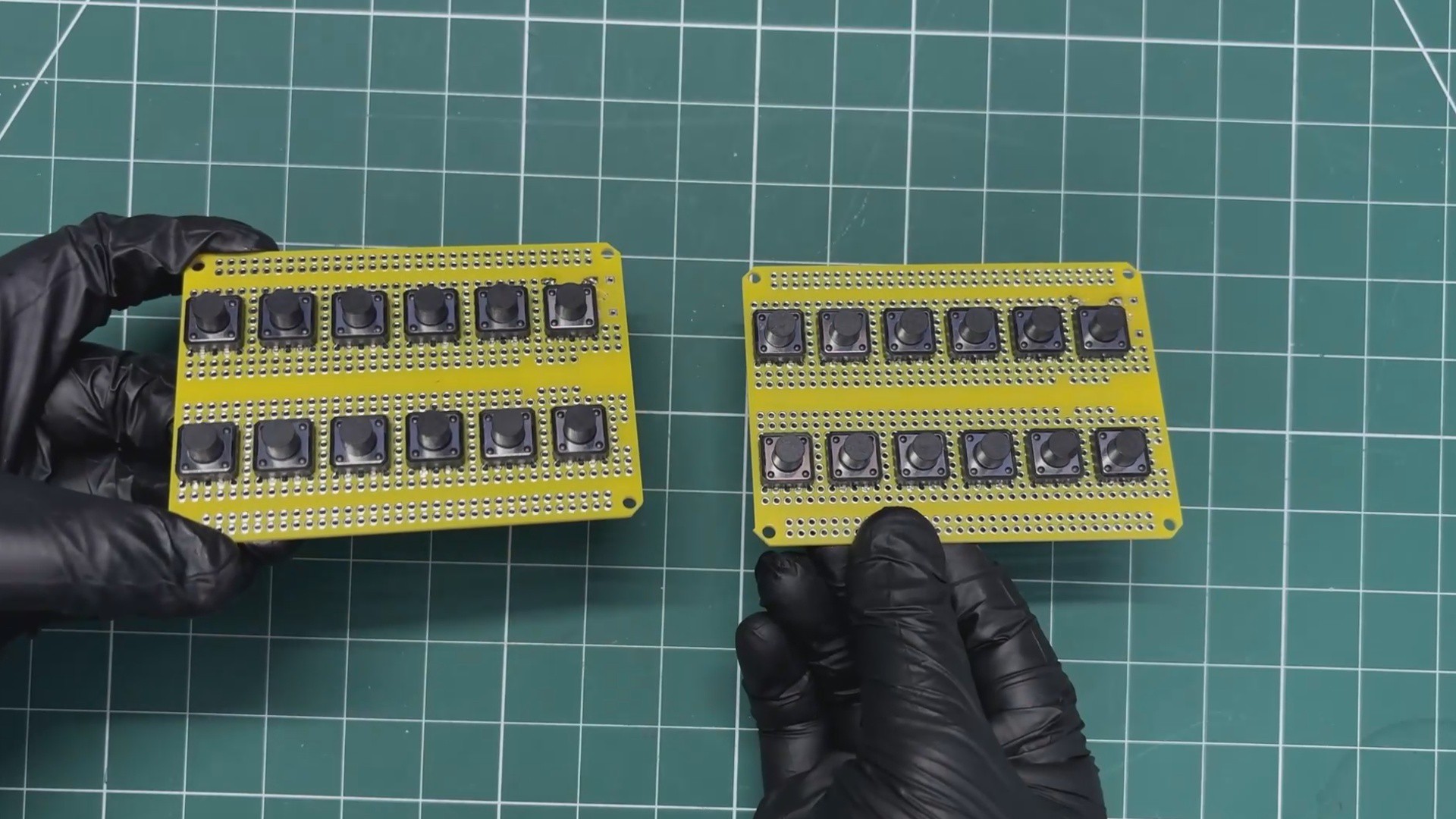
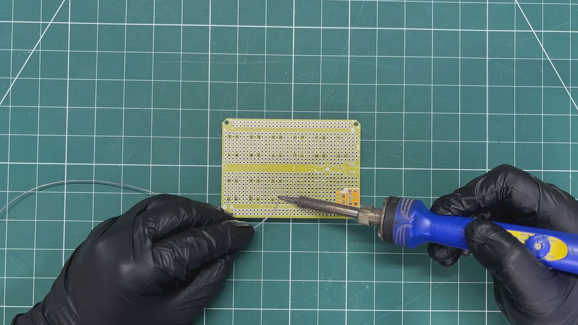
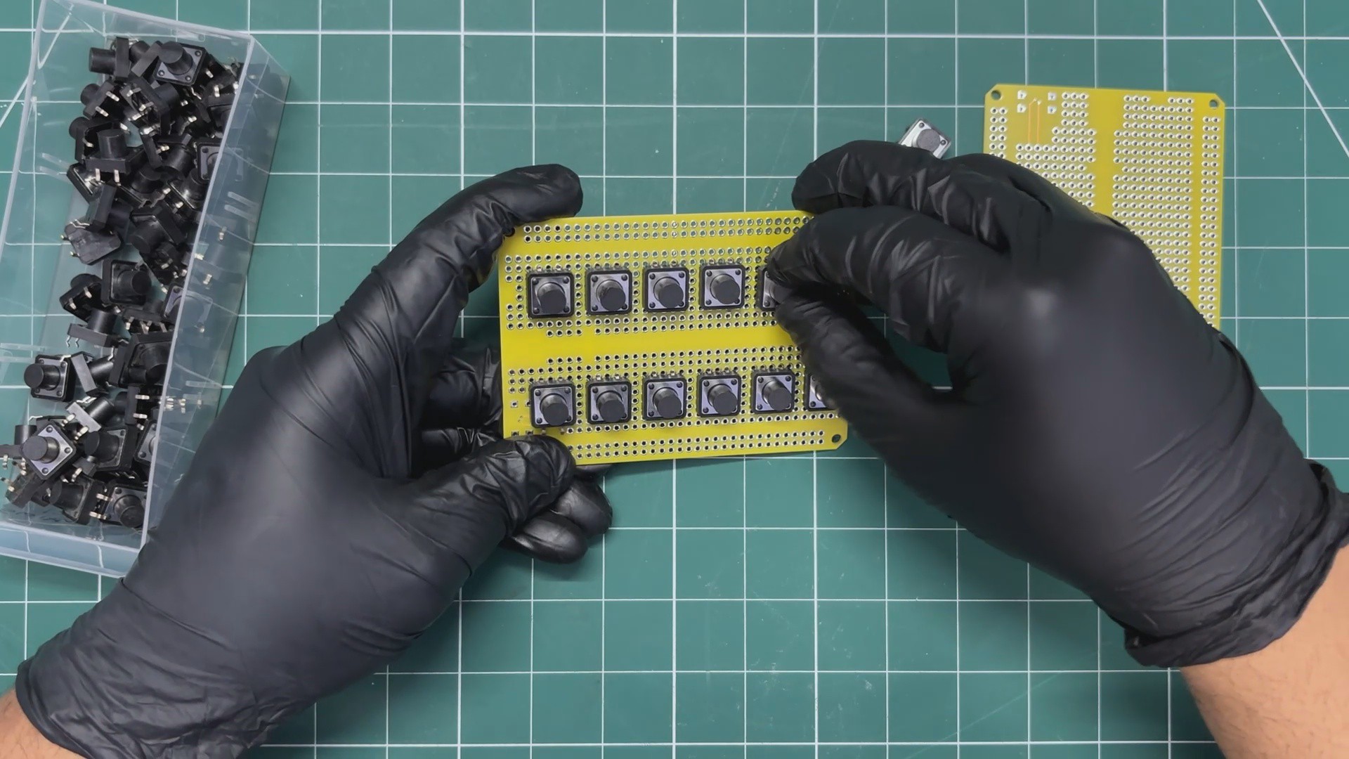
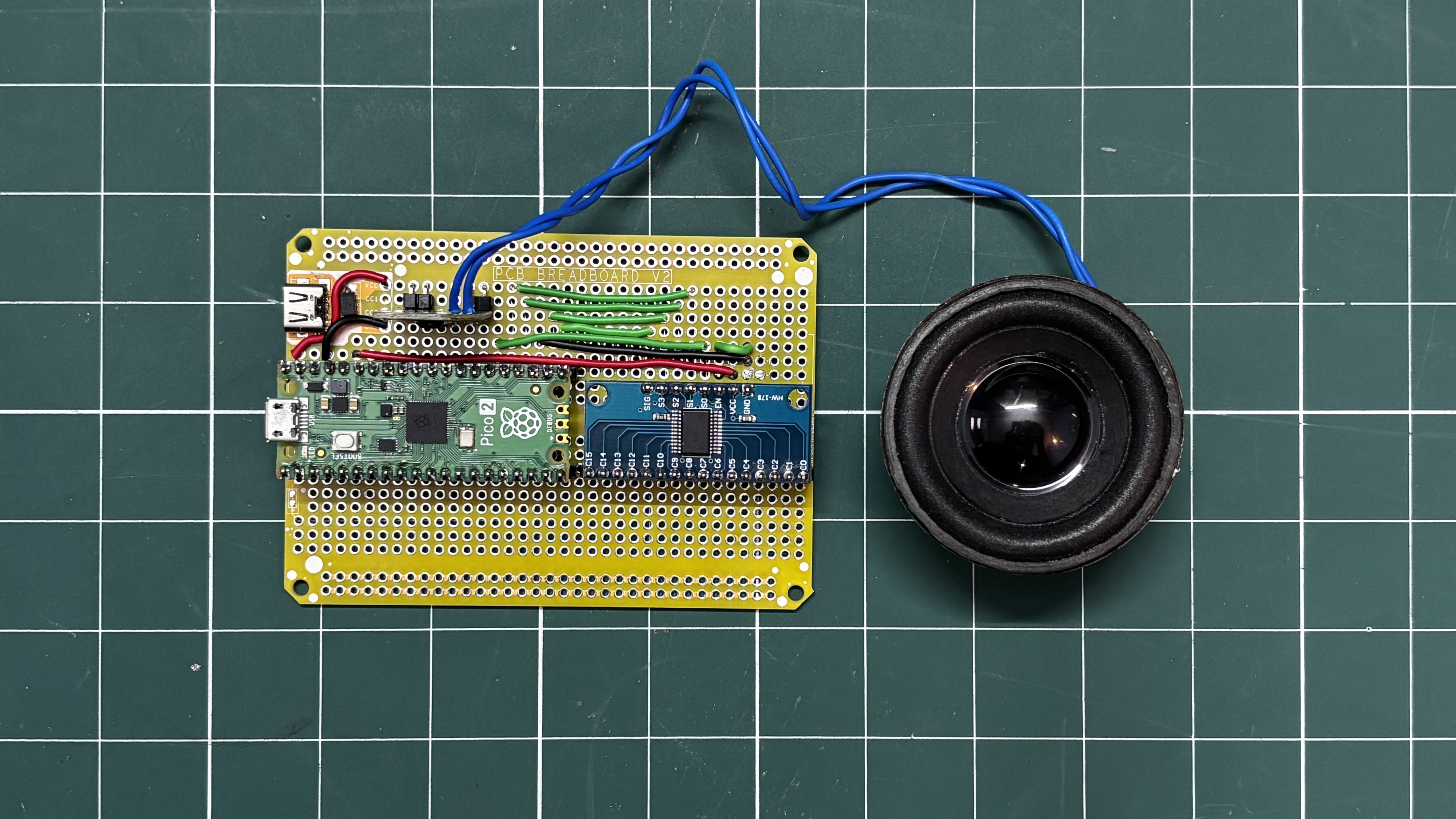
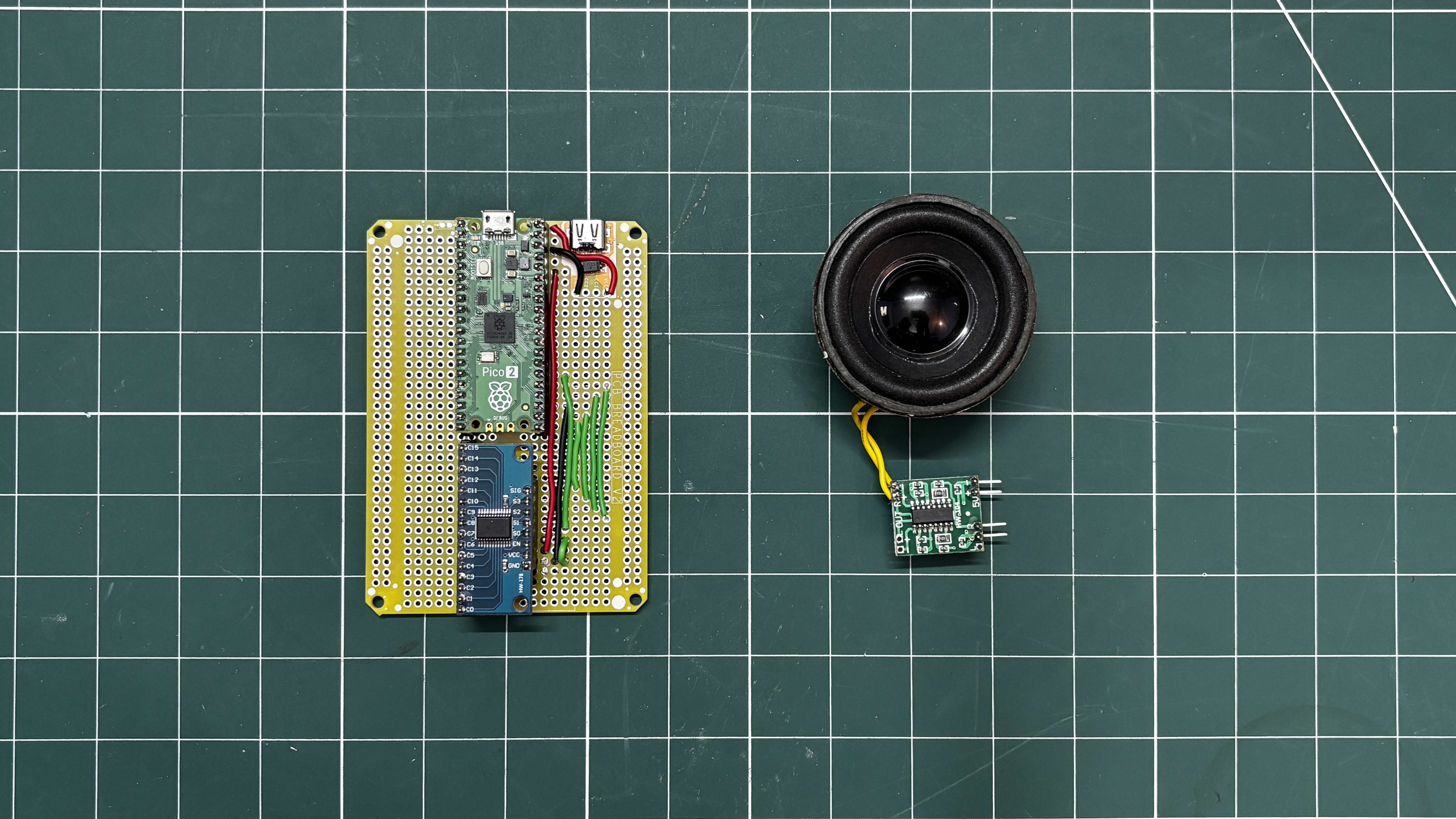
The second phase was a more permanent PCB-based version. For this stage, a previously designed PCB breadboard was used, and the entire circuit was rebuilt on it to create a cleaner and more durable setup compared to the temporary breadboard prototype.
This project mainly serves as a demonstration platform for an upcoming, more advanced synthesizer project. The future version will include dedicated buttons, potentiometers, and a display. Silent mechanical switches will also be used so the instrument operates quietly, since the push buttons used in the current PCB version produce audible clicks when pressed.
Overall, the current Pi Synth setup functions as a demo board that will primarily be used for experimenting with and refining the code for the upcoming synthesizer. This Article covers the complete build process, including both the breadboard prototype and the more permanent PCB breadboard version.
CD74HC4067 MULTIPLEXER
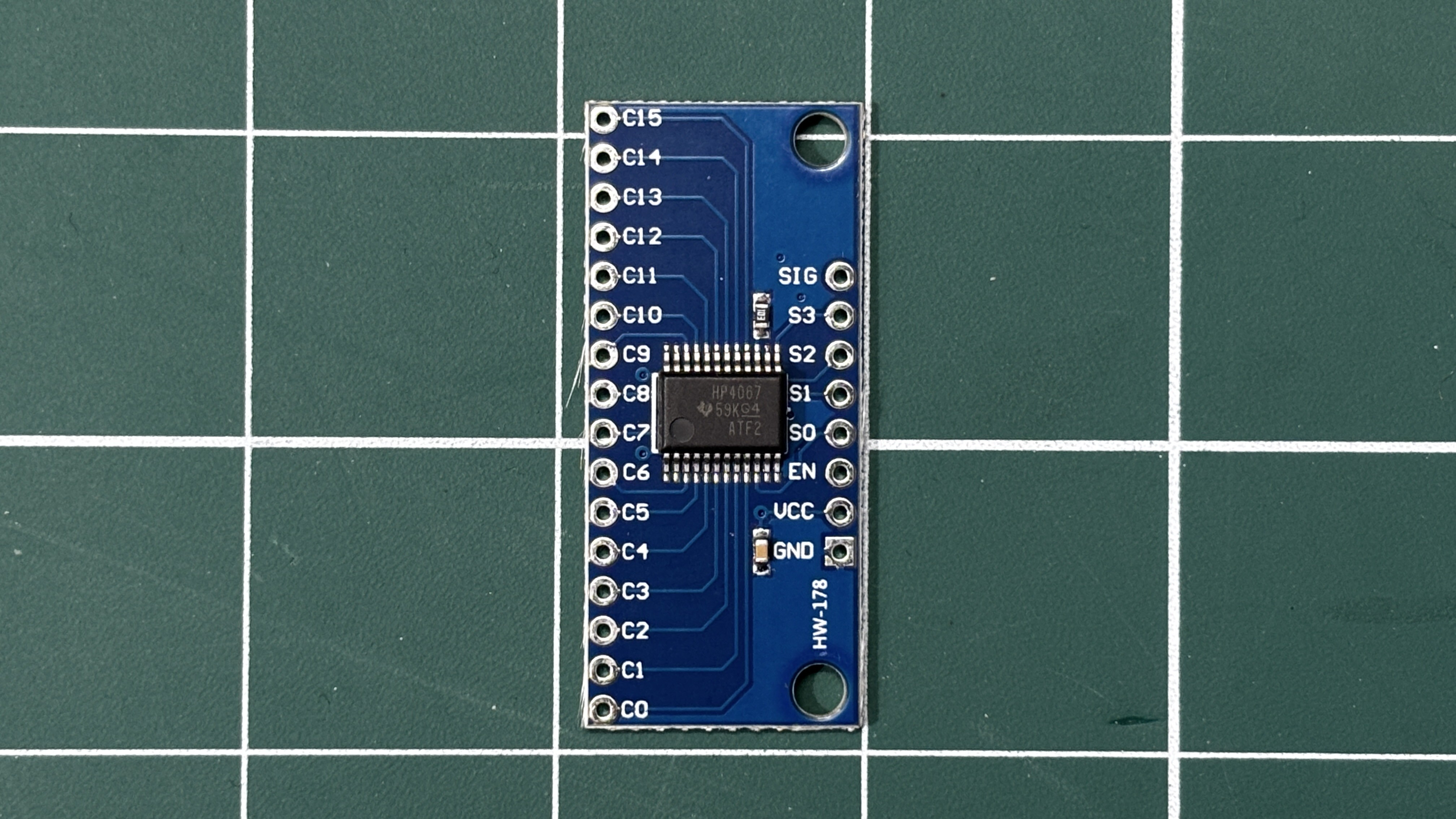
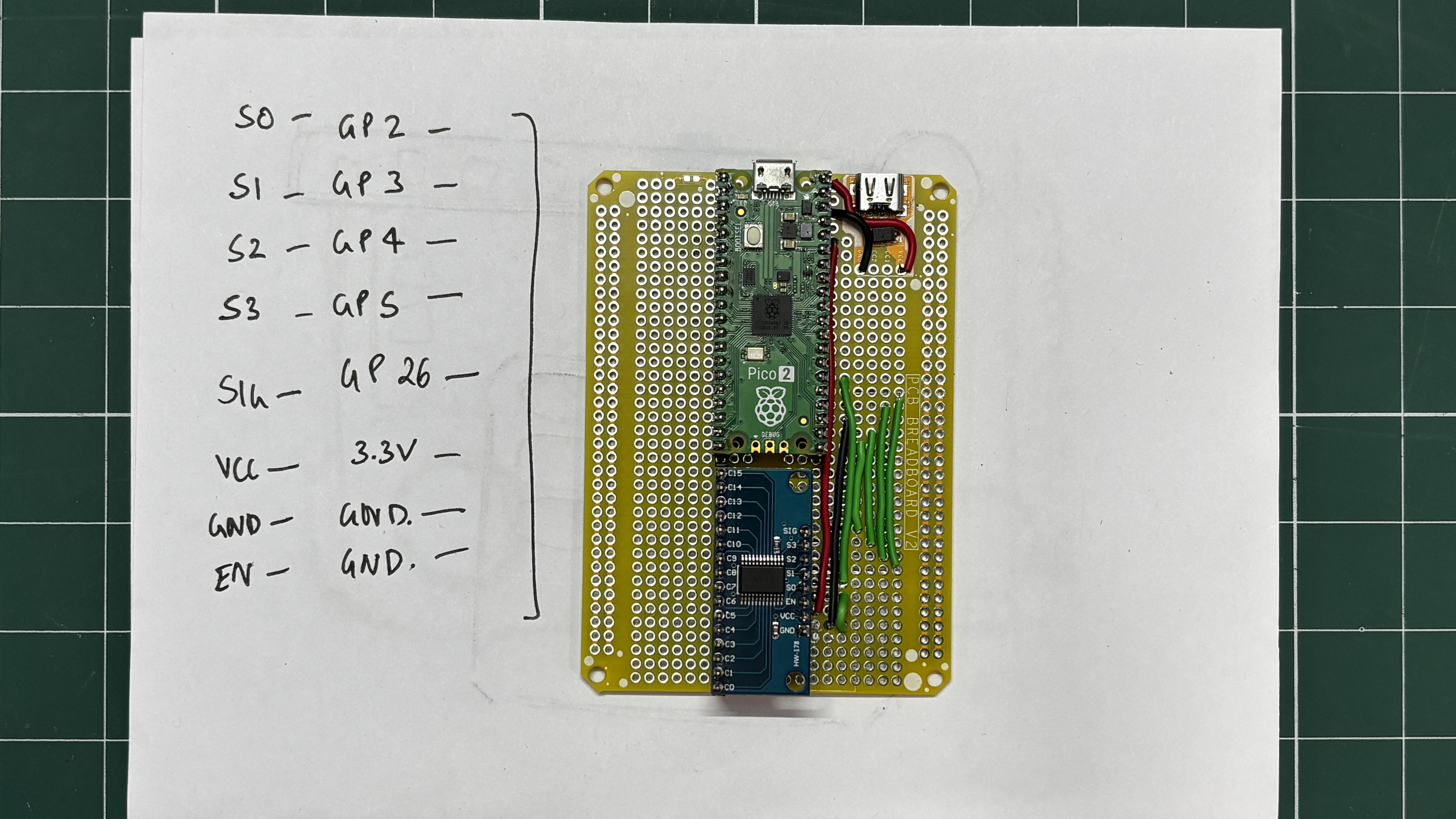
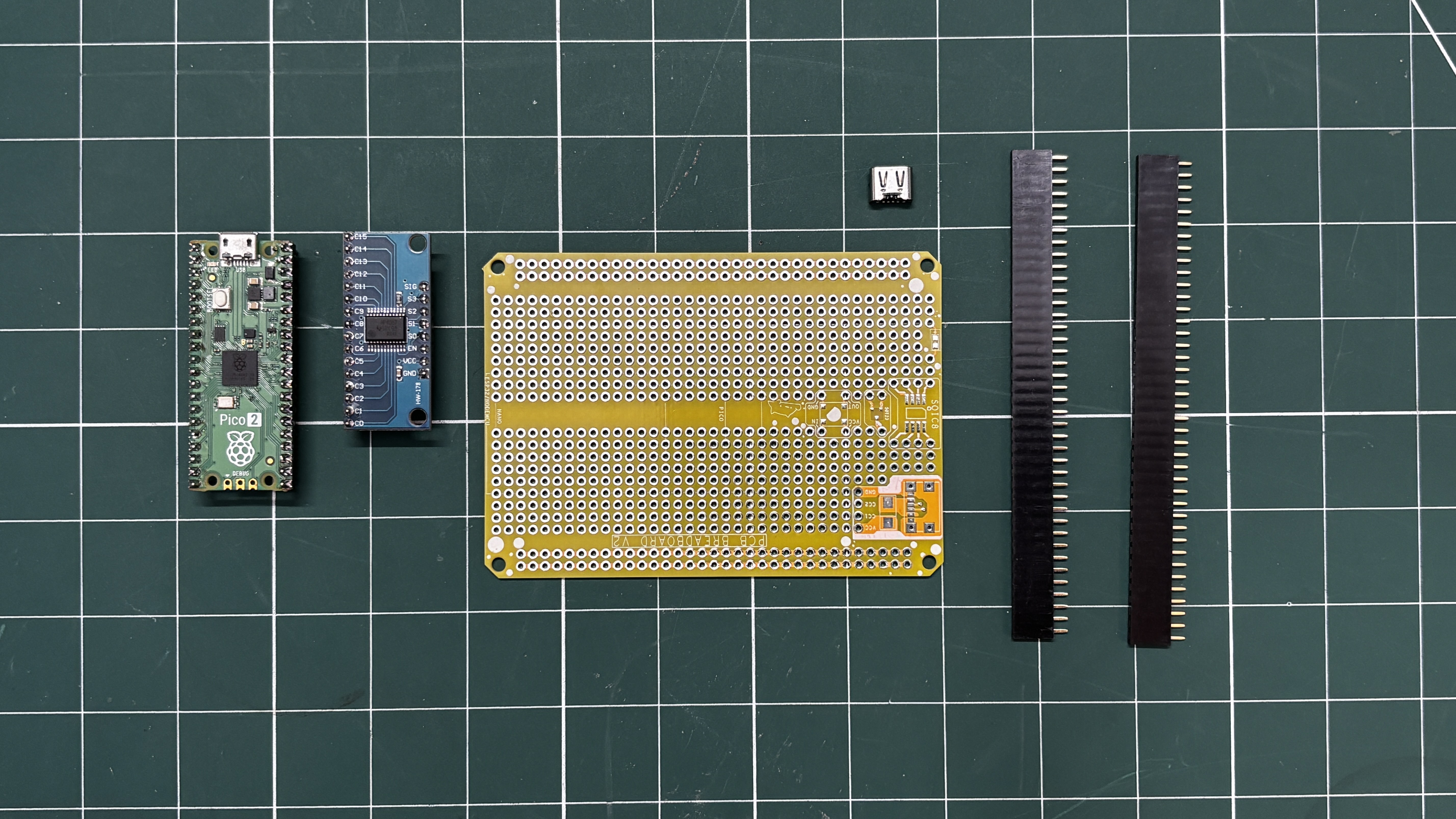
In our project we used the CD74HC4067 Multiplexer IC, which allows many input signals to be read using only a few microcontroller pins. This IC acts like an electronic rotary switch: it connects one of sixteen input channels to a single output pin at a time, depending on the control signals provided.
The CD74HC4067 has 16 signal channels (C0–C15) and one common pin (SIG). Four select pins (S0–S3) determine which channel is currently connected to the common pin. By sending a binary value to these four select lines, the microcontroller can quickly choose which input channel to read. For example, when the select lines represent binary 0000, channel C0 is connected; when they represent 0001, channel C1 is connected, and so on up to C15.
In our Synth project, the multiplexer is used to expand the number of buttons that the microcontroller can read. Instead of dedicating a separate GPIO pin for each key, all buttons are connected to the multiplexer channels. The microcontroller cycles through the channels rapidly by changing the select pins and reading the shared SIG pin. This scanning happens fast enough that it appears as if all buttons are being read simultaneously.
Using the CD74HC4067 greatly reduces the number of required GPIO pins, making it possible to implement a 16-button keyboard and control inputs while using only five microcontroller pins (four select pins and one signal pin). This makes the circuit simpler, more scalable, and ideal for compact projects like this DIY synthesizer.
BREADBOARD SETUP

Using the provided wiring diagram, we prepared a basic breadboard setup consisting of a Pico connected to a CD74HC4067 module. We paired the S0 pin of the multiplexer with GPIO20, S1 with GPIO19, S2 with GPIO18, S3 with GPIO17, and the SIGNAL pin with GPIO16.
Sixteen buttons were connected to the sixteen channels of the multiplexer IC, and they are all connected to GND. When a button is pressed, the corresponding channel is pulled down, which is registered as a button press. The remaining buttons were paired with the remaining GPIO pins of the Pico.
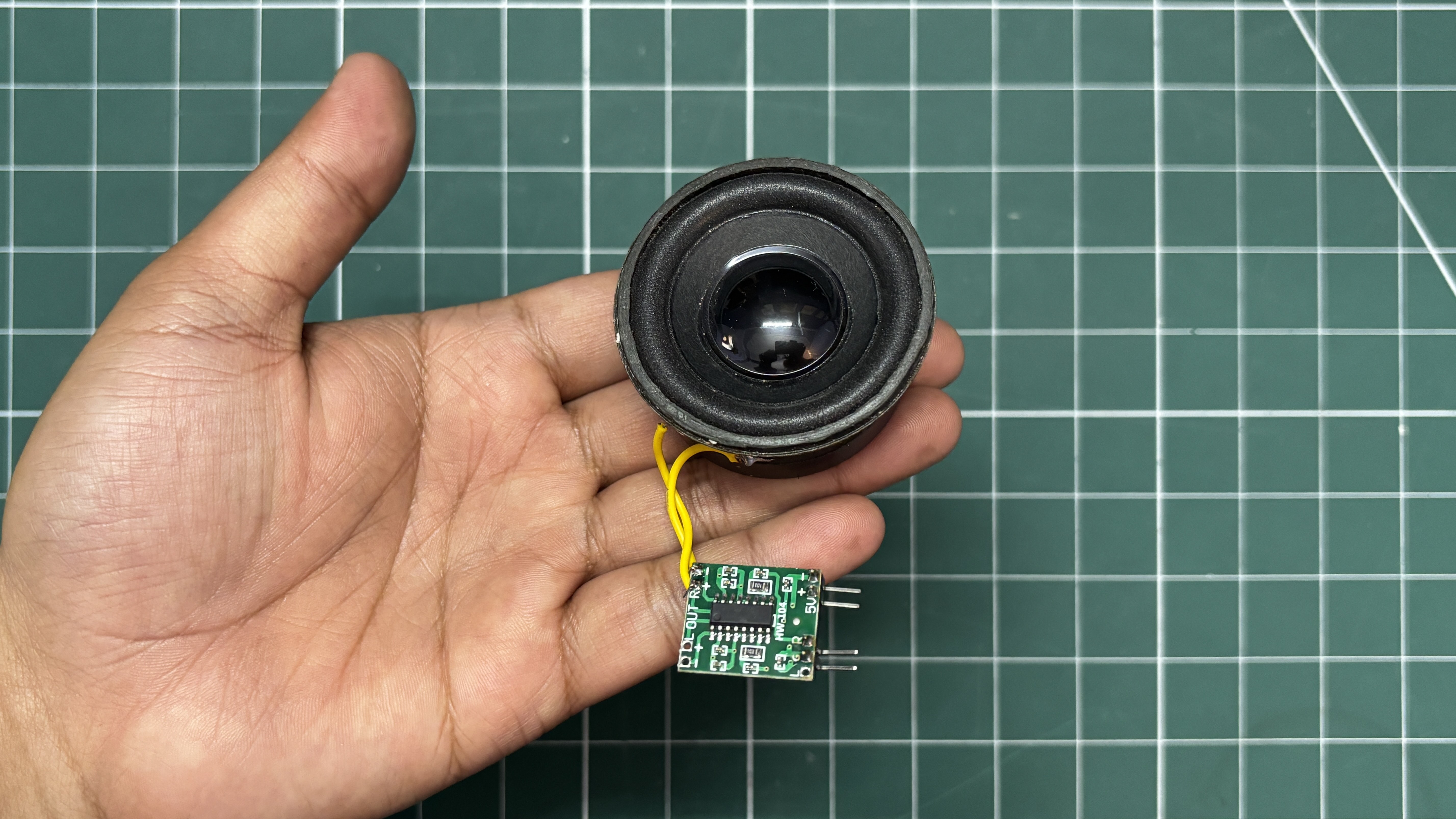
For audio output, we are using a PAM8403 audio amplifier module connected to a 5W 8Ω speaker. The amplifier input is connected to GPIO21 of the Pico.
We used a total of three breadboards stacked together to create a larger breadboard surface. On this setup, we placed all the buttons, the audio module, the multiplexer, and the main microcontroller and wired everything together using single-core copper wire.
CODE
This was the main code we used in our project and it's a simple one.
#include <math.h>
// ================= MUX =================
#define S0 20
#define S1 19
#define S2 18
#define S3 17
#define SIG 16
// ================= AUDIO =================
#define AUDIO_PIN...
Read more »

 hesam.moshiri
 Mrinnovative