Close
0%
0%

Omni-corder

Fully functional scanner, inspired by Star Trek's Tricorder

Similar projects worth following
0 followers
This is very much not a replica prop or trying to be an actual Tricorder because that would get me sued but it is very much an inspired by TNG Tricorder, fully functional, field ready, multi-sensor device.

This is the Omni-corder.

Truth be told I was inspired by an ad I saw on tiktok for the Radiacode radiation detector/spectrometer which was leaning heavily into the Trek vibe and I thought to myself, I wonder if I could somehow incorporate a Radiacode into a tricorder 3d print... after spending the night iterating and going down a rabbit hole of my own thoughts I eventually came up with the Omni-corder.

The intention is to have a single hand-held device, battery powered, which can 'scan' in various modes.

I started out with the idea of using the traditional MET, BIO, GEO modes and trying to figure out what sensors to put on there but eventually I decided to work backwards from what sensors I want and then figure out the UI after that.

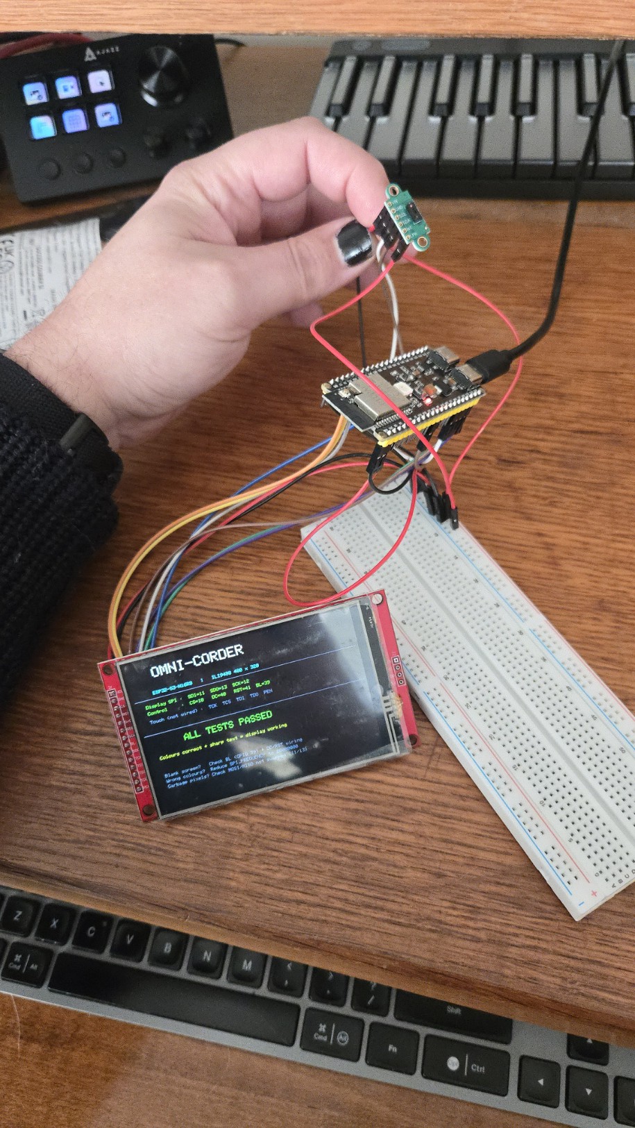
The OMNI-CORDER is a handheld, self-contained scientific field instrument built around three ESP32-S3 processors, a 3.5" TFT touchscreen display, and a sensor suite that covers radiation spectrometry, real-time 3D depth mapping, thermal imaging, environmental monitoring, GPS, and dual 5MP cameras.

It's inspired by the tricorders of Star Trek: The Next Generation — but every sensor on this device is real and functional. Note for Paramount - This is not a prop, not a cosplay replica, and not LCARS.

This is a fully functional field device that hopefully will look like it came out of the Trek-verse.

The star of the show, what made me want to do this project and doing a lot of the heavy lifting in terms of raw science and sci-fi vibes, is the Radiacode 110. Doing all the isotope spectrum detection and analysis, acting as a radiation detector for beta and gamma rays and helping to identify what sources are and what the background readings are. Just by having this I feel 1000x cooler than before and I've learnt a load of stuff about radiation and spectrometry just by working out how to use it.

To compliment that I want to make sure the Omni-corder has a decent suite of scan tools. The overview is: Radiation detection, type of radiation, background spectrometry, 3D scanner for pointclouds and textured models, thermal imaging, environmental sensors (temp, pressure, humidity etc),  I'm working in VSC for the coding, using Claude Code to iterate and debug. I'm also using Claude to help organise my brain dumps into actually useful project documents.

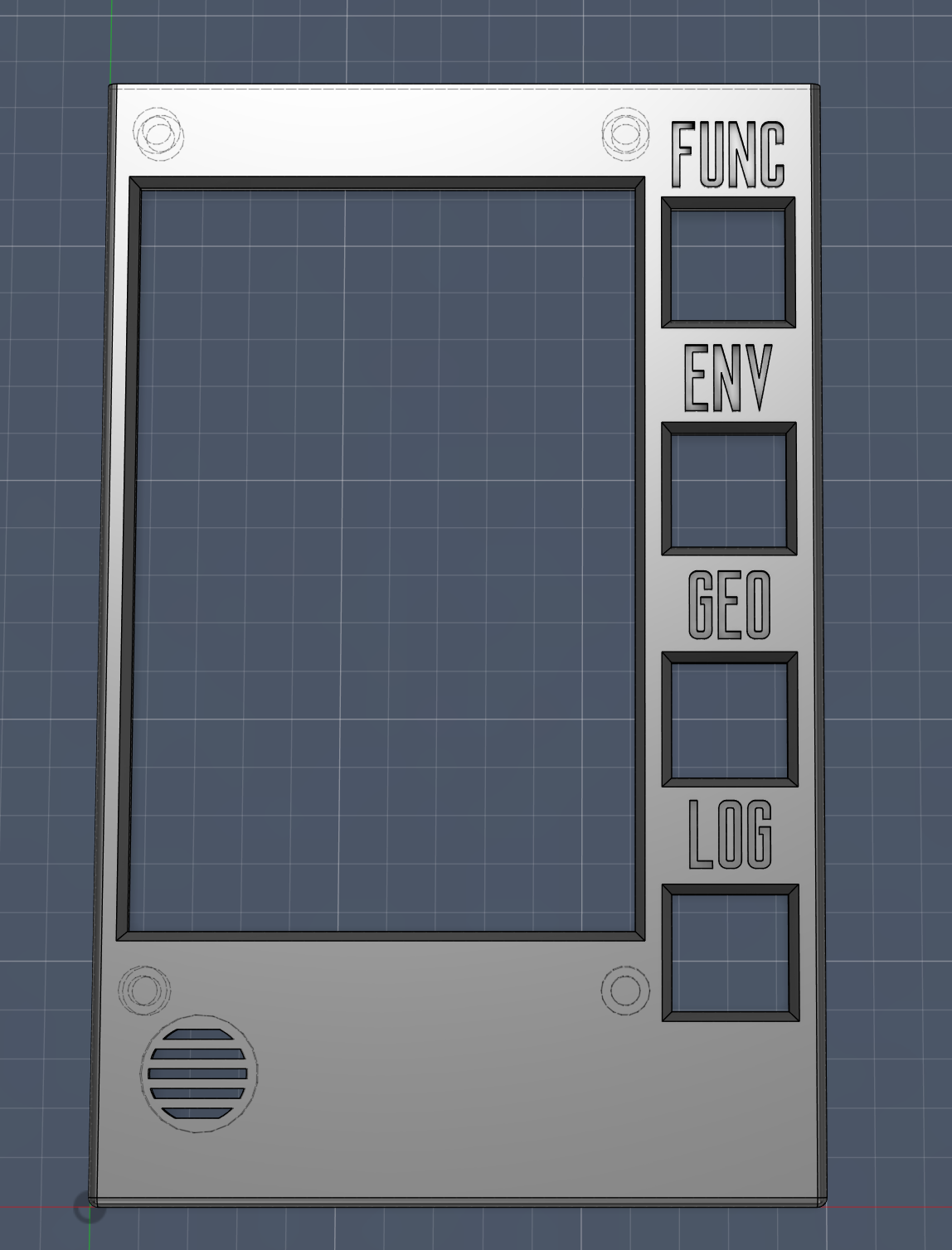
The device is going to have three modes: ENV (enviromental), GEO (geological), LOG (for logging data). Each mode will have several 'pages' within the UI to give the user data around specific use cases or sensor suites. Here's how I plan for each of these modes to play out:

ENV Mode — Environmental Analysis

Atmosphere & Weather

  • Temperature, humidity, and barometric pressure (BME688)
  • Dew point calculation
  • Pressure trend graphing
  • Air quality index and VOC gas detection (BME688 / BSEC2)
  • UV index (VEML6070)
  • Ambient light level in lux (BH1750)

Radiation & Electromagnetic

  • Background gamma dose rate (Radiacode 110)
  • EMF / magnetic field strength (Hall effect module)

Location & Navigation

  • Multi-constellation GPS fix (GPS, BDS, GLONASS, GALILEO, QZSS, SBAS)
  • Waypoint marking
  • GPS track logging
  • Compass heading (HMC5883L)

Logging

  • All sensor readings timestamped and GPS-tagged to microSD
  • Continuous background logging across all ENV pages

GEO Mode — Geological & Material Analysis

3D Spatial Capture

  • Live 8×8 depth map display (VL53L5CX ToF)
  • Static single-frame 3D point cloud with perspective projection
  • IMU-guided sweep — accumulate depth frames across multiple positions
  • Photorealistic textured 3D model — OV5640 camera imagery projected onto depth geometry
  • On-device model display; saved to SD card as PLY file with texture map

Thermal Imaging

  • 32×24 live thermal array (MLX90640)
  • Thermal overlay on camera feed with adjustable opacity
  • Thermal mapped onto 3D geometry
  • Temperature distribution across scanned object
  • Saved as raw thermal data, raw JPEG, and blended JPEG

Radiation / Spectrometry

  • Real-time gamma dose rate and CPS (Radiacode 110)
  • Full gamma spectrum display
  • Isotope identification

Material Inference

  • Multi-sensor correlation across spectrometry, thermal, and visual data
  • Cross-reference against materials database
  • Confidence levels shown for all identifications
  • Analysis method always labelled (spectroscopic / thermal / visual / multi-sensor)

Illumination

  • 10W white rear LED for scan illumination (MOSFET-switched)
  • 3W UV (365–370 nm) rear LED for fluorescence scanning
  • One active at a time

Logging

  • All scan data, spectra, and 3D models timestamped and GPS-tagged to microSD

LOG Mode — Field Notes & Documentation

Photography

  • 5MP stills via front OV5640 autofocus camera
  • GPS coordinates and sensor data embedded in EXIF metadata
  • Photo...
Read more »

  • 1 × Radiacode 110 Portable radiation detector and spectrometer Csl (Tl) 8.4% ±0.3% FWHM 77 cps = 1 μSv/h for Cs-137
  • 3 × ESP32-S3-N16R8 16 MB flash, 8 MB PSRAM
  • 2 × OV5640 5MP autofocus camera
  • 1 × VL53L5CX 8×8 Time of Flight depth sensor
  • 1 × MLX90640 32×24 thermal array

View all 11 components

  • And now you're up to date

    Motley3 hours ago 0 comments

    So with a working TFT, ToF and a Radiacode, I started to think about the housing and overall design for the project. I had wanted to go with a flip design originally, like the TNG Tricorder, but that was clearly out of the question if I wanted to be able to have the Radiacode 110 in there, whilst a ridiculously small footprint for what it is and what it does, it's length means that if I were to add flip to the omni-corder, it would still have to be really long. So I scrapped that idea and have gone with just a chunky unit. First design was just a box with space for the screen and a slot for the Radiacode to slide into. A key consideration in this whole design is that I want to be able to take the Radiacode out easily so that I can use it standalone still.

    The second iteration of this came after I started to flesh out the UI concept a bit more. I decided that rather than having everything on the touchscreen as I had planned at the start, I'd add some physical buttons for the mode and page switching. I thought this would give the device a nice retro-futuristic vibe, be practical and free up UI screen space and be a direct call-back to the TNG tricorder design.

    So that's what's happening with that.

    First concept was to have everything slot in from the top, then have a 'cap', housing sensors, connect to the top to finish it off.

    Next itiration was to create a layerd approach to the unit, still with the cap idea.

    Now I'm working on a third iteration, where I'm scrapping the whole cap concept and leaning fully into the layers idea and since the entire project direction recently switched to using 3 ESP32 boards rather than one, a complete design overhaul is needed.

    I've ordered all but a couple of the components now. Haven't got the range finder, speaker or UV indexer yet.

    Everything else should arrive in a week or two.

    Next log should give some update about the new design and some new component testing. Hopefully all the camera woes will have been sorted and I'll be able to start testing those.

  • The story so far...

    Motley3 hours ago 0 comments

    I had intended to start at day one, logging everything as I go, but it took way longer to get a creator account set up than anticipated and I started building because... I have no patience.

    So this first log entry is just to get you up to speed.

    The first bunch of components I ordered were:

    - ESP32-S3-N16R8 DevKit (UICPAL brand)
    - ILI9488 3.5" TFT display, red PCB breakout
    - VL53L5CX ToF sensor, small green breakout board
    - OV2640 camera bare sensor, 24-pin gold FPC, M12 lens barrel
    - INMP441 MEMS microphone x1
    - TP4056 USB-C charge module

    Physical inspection notes:
    - ESP32-S3 board: UICPAL brand, N16R8 confirmed on module label. Two USB-C ports (OTG and TTL). Small U.FL antenna socket on module (external antenna optional — PCB trace antenna sufficient for testing).
    - Display: Red PCB, 14-pin header bottom edge. MicroSD slot on back (J2 header). Touch digitiser (XPT2046) shares header.
    - VL53L5CX: Small green board, no pull-up resistors visible on SDA/SCL. LPN pin present (must tie to 3.3 V).
    - OV2640: Bare sensor with M12 lens. Needs a host board with FPC socket (AI Thinker ESP32-CAM or equivalent breakout).
    - INMP441: Small breakout, labelled pins.

    It was here that I realised I needed a breakout board for the camera, this became a real pain in the arse to find, I didn't want one with a camera but it seemed really hard to find one without. Anyway, I ordered another one, with a cam, which I thought was also a 2MP 2046. It wasn't. It was a breakout board and it did have a cam with it but it was the 0.3MP 3040... and it didn't have any usb connections... so back to aliexpress, feeling really annoyed at myself for not looking closely enought at listings, that's when I saw the flash sale for the 2x ESP32S3's with integrated cam board (FPC socket) and 5MP OV5640 cameras. Perfect. As of writing this, these are on order and should arrive in the next week or two. On with the story...

    Installed PlatformIO IDE extension in VS Code.

    This next bit took so much longer than it should have:

    Phase 1: Display + ToF 

    Duration: ~3–4 hours (estimated)
    Activity: Hardware bring-up, debugging, combined display demo

    This was the main hardware bring-up session. Several issues encountered and resolved before everything worked. The main issue was that the TFT did not work as expected and there was basically no help or documentation online.

    Display (ILI9488) bring-up

    Wired ILI9488 to ESP32-S3 per pin assignments in TECH_STACK.md. Initial attempts failed silently or crashed.

    Issues encountered:
    1. Guru Meditation / StoreProhibited at boot — caused by using GPIO 35/36/37 for SPI. These are internally wired to the OPI PSRAM chip and cannot be used as general GPIO. Moved SPI to GPIO 10/11/12.
    2. Guru Meditation even with bare sketch — flash mode was DIO. The N16R8 requires QIO mode. Added `board_build.flash_mode = qio` and `board_build.arduino.memory_type = qio_opi` to platformio.ini.
    3. Serial Monitor completely silent — ESP32-S3 native USB requires `-DARDUINO_USB_CDC_ON_BOOT=1` build flag. Without it, the Serial class has no output.
    4. Crash inside tft.init() — TFT_eSPI defaulted to SPI3 (GPIO 35/36/37 area). GPIO 10–12 are on SPI2. Fixed with `-DUSE_HSPI_PORT` and `-DTFT_MISO=-1`.

    After resolving all four issues, the display worked correctly: full 480x320 colour, correct colours, no flickering.

    ToF Sensor (VL53L5CX) bring-up

    Wired VL53L5CX to I2C on GPIO 8/9. Added external 4.7 kOhm pull-ups on SDA and SCL.

    Issues encountered:
    5. VL53L5CX header not found — include path was wrong. Correct header is `SparkFun_VL53L5CX_Library.h` (not `_Arduino_Library.h`).
    6. I2C Error -1 / sensor not responding — AliExpress breakout has no onboard pull-up resistors. Added 4.7 kOhm from SDA to 3.3 V and SCL to 3.3 V externally.
    7. Sensor dots (retrying forever at startup) — LPN pin was floating. Wired LPN to 3.3 V. Sensor responds immediately after.

    After resolving issues, sensor confirmed working. Reads 8x8 depth array (64 values per frame)...

    Read more »

View all 2 project logs

Enjoy this project?

Share

Discussions

Does this project spark your interest?

Become a member to follow this project and never miss any updates