Motley
-
Design is not my friend
03/21/2026 at 09:22 • 0 commentsI'm thinking I could loose the bottom part of the length by moving the ESP that was going there, to the next layer... means longer wire running, across multiple layers but a shorter design... Anyone got thoughts?
-
Housing update
03/20/2026 at 18:46 • 0 commentsThe housing/case, whatever you want to call it has evolved quite a bit since the last update.
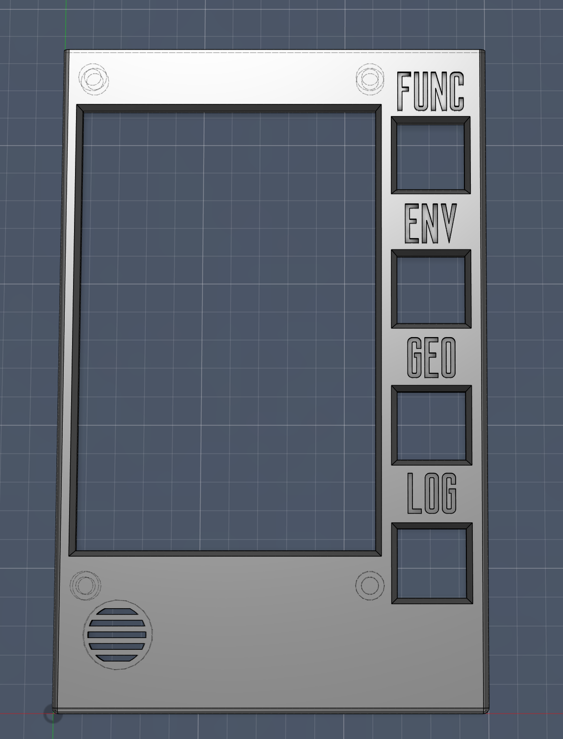
I've iterated and come up with something that whilst quite brutalist and monolithic, still feels 'hand held' and depending on the size of said hands, should be comfortable in one hand. Have been through about a spool of PLA getting things like hole and standoff placement just right, even with calipers and a keen eye, it takes a little tweaking each time.I'm still working on the idea of creating layers.
This first 'base' layer will be housing the Radiacode 110, powerboard with double 5000mah 3.7v battery cell things, 1x ESP32-S3 board, which will be the main sensor board, the rear facing 5MP OV5640 camera along with IR thermal sensor, the 10w LED flashlight, UV light and omnidirectional microphone.
We'll see how things fit but the next layer is planned to hold the 2x ESP32-S3 boards for the cameras, the 9-way sensor (IMU, mag, comp) and the GPS module. probably need to fit the push button pcb on this layer too.
The top layer will have the front facing cam and mic, same as the bottom layer. It will also have the screen with it's ESP32-S3 and the gas/temp/humidity sensor.
I think that's all the things?
Still awaiting delivery of the screen and thermal module. Then it's just working out how to wire it all up and write the code! I'm sure there will be no problems at all 🤣
![]()
-
Display update
03/16/2026 at 10:38 • 0 commentsQuick update. Have decided to swap out the TFT display for an RGB with it's own ESP32 S3. Bringing the total processor count to 4. Which is the limit since the power board has 4 5v outputs.
The main reasoning behind this being that we're upgrading from 20fps to 60fps and much nicer, smoother animatins for the UI and rendering of video/images. It will also free up the main S3 board for sensor input and talking to the Radiacode 110. The new S3 on the display unit will handle display and SD card duties only.
-
And now you're up to date
03/15/2026 at 20:08 • 0 commentsSo with a working TFT, ToF and a Radiacode, I started to think about the housing and overall design for the project. I had wanted to go with a flip design originally, like the TNG Tricorder, but that was clearly out of the question if I wanted to be able to have the Radiacode 110 in there, whilst a ridiculously small footprint for what it is and what it does, it's length means that if I were to add flip to the omni-corder, it would still have to be really long. So I scrapped that idea and have gone with just a chunky unit. First design was just a box with space for the screen and a slot for the Radiacode to slide into. A key consideration in this whole design is that I want to be able to take the Radiacode out easily so that I can use it standalone still.
The second iteration of this came after I started to flesh out the UI concept a bit more. I decided that rather than having everything on the touchscreen as I had planned at the start, I'd add some physical buttons for the mode and page switching. I thought this would give the device a nice retro-futuristic vibe, be practical and free up UI screen space and be a direct call-back to the TNG tricorder design.
So that's what's happening with that.
First concept was to have everything slot in from the top, then have a 'cap', housing sensors, connect to the top to finish it off.
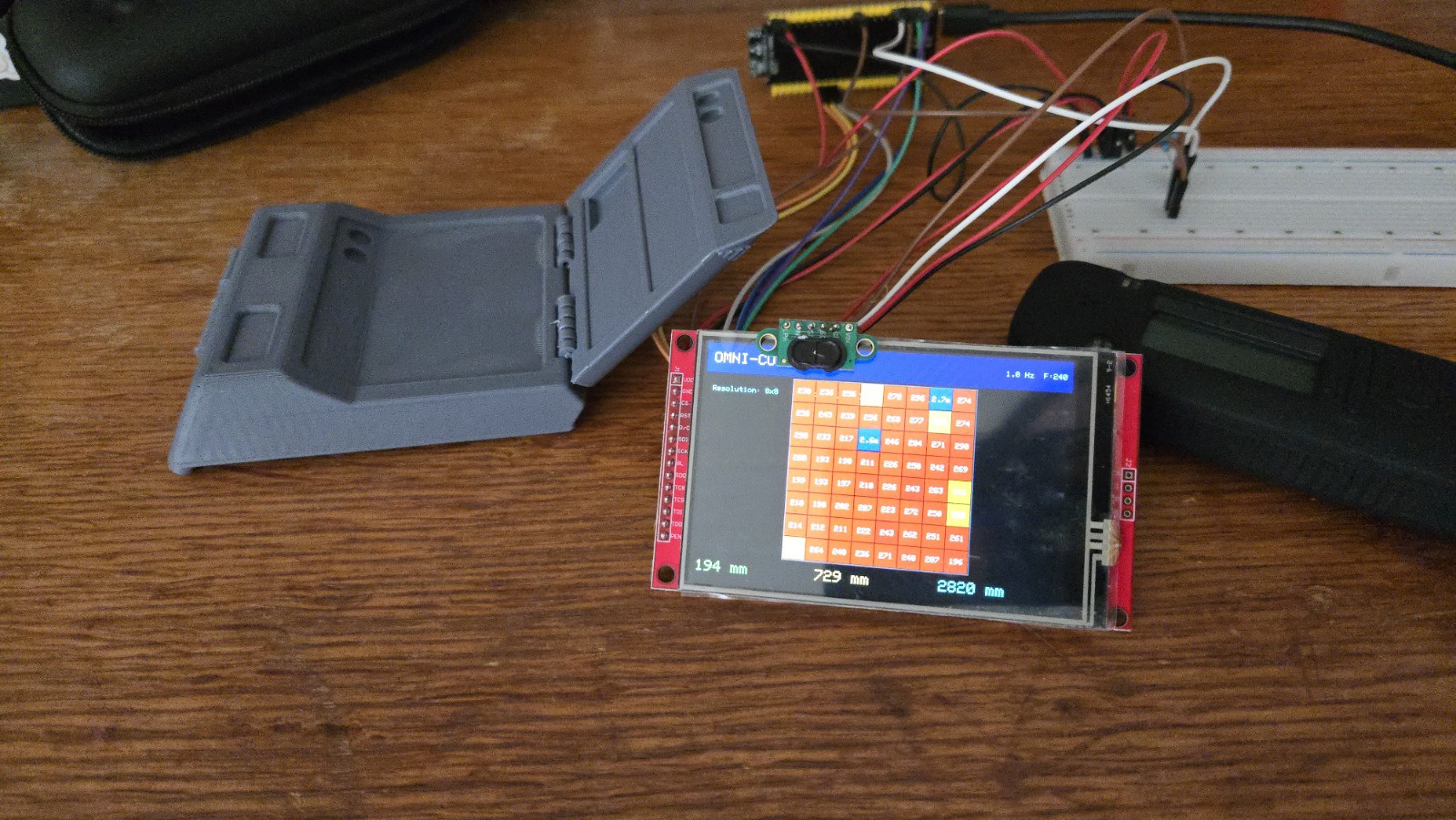
Next itiration was to create a layerd approach to the unit, still with the cap idea.
![]()
Now I'm working on a third iteration, where I'm scrapping the whole cap concept and leaning fully into the layers idea and since the entire project direction recently switched to using 3 ESP32 boards rather than one, a complete design overhaul is needed.
I've ordered all but a couple of the components now. Haven't got the range finder, speaker or UV indexer yet.
Everything else should arrive in a week or two.
Next log should give some update about the new design and some new component testing. Hopefully all the camera woes will have been sorted and I'll be able to start testing those.
-
The story so far...
03/15/2026 at 19:42 • 0 commentsI had intended to start at day one, logging everything as I go, but it took way longer to get a creator account set up than anticipated and I started building because... I have no patience.
So this first log entry is just to get you up to speed.
The first bunch of components I ordered were:
- ESP32-S3-N16R8 DevKit (UICPAL brand)
- ILI9488 3.5" TFT display, red PCB breakout
- VL53L5CX ToF sensor, small green breakout board
- OV2640 camera bare sensor, 24-pin gold FPC, M12 lens barrel
- INMP441 MEMS microphone x1
- TP4056 USB-C charge modulePhysical inspection notes:
- ESP32-S3 board: UICPAL brand, N16R8 confirmed on module label. Two USB-C ports (OTG and TTL). Small U.FL antenna socket on module (external antenna optional — PCB trace antenna sufficient for testing).
- Display: Red PCB, 14-pin header bottom edge. MicroSD slot on back (J2 header). Touch digitiser (XPT2046) shares header.
- VL53L5CX: Small green board, no pull-up resistors visible on SDA/SCL. LPN pin present (must tie to 3.3 V).
- OV2640: Bare sensor with M12 lens. Needs a host board with FPC socket (AI Thinker ESP32-CAM or equivalent breakout).
- INMP441: Small breakout, labelled pins.It was here that I realised I needed a breakout board for the camera, this became a real pain in the arse to find, I didn't want one with a camera but it seemed really hard to find one without. Anyway, I ordered another one, with a cam, which I thought was also a 2MP 2046. It wasn't. It was a breakout board and it did have a cam with it but it was the 0.3MP 3040... and it didn't have any usb connections... so back to aliexpress, feeling really annoyed at myself for not looking closely enought at listings, that's when I saw the flash sale for the 2x ESP32S3's with integrated cam board (FPC socket) and 5MP OV5640 cameras. Perfect. As of writing this, these are on order and should arrive in the next week or two. On with the story...
Installed PlatformIO IDE extension in VS Code.
This next bit took so much longer than it should have:
Phase 1: Display + ToF
Duration: ~3–4 hours (estimated)
Activity: Hardware bring-up, debugging, combined display demoThis was the main hardware bring-up session. Several issues encountered and resolved before everything worked. The main issue was that the TFT did not work as expected and there was basically no help or documentation online.
Display (ILI9488) bring-up
Wired ILI9488 to ESP32-S3 per pin assignments in TECH_STACK.md. Initial attempts failed silently or crashed.
Issues encountered:
1. Guru Meditation / StoreProhibited at boot — caused by using GPIO 35/36/37 for SPI. These are internally wired to the OPI PSRAM chip and cannot be used as general GPIO. Moved SPI to GPIO 10/11/12.
2. Guru Meditation even with bare sketch — flash mode was DIO. The N16R8 requires QIO mode. Added `board_build.flash_mode = qio` and `board_build.arduino.memory_type = qio_opi` to platformio.ini.
3. Serial Monitor completely silent — ESP32-S3 native USB requires `-DARDUINO_USB_CDC_ON_BOOT=1` build flag. Without it, the Serial class has no output.
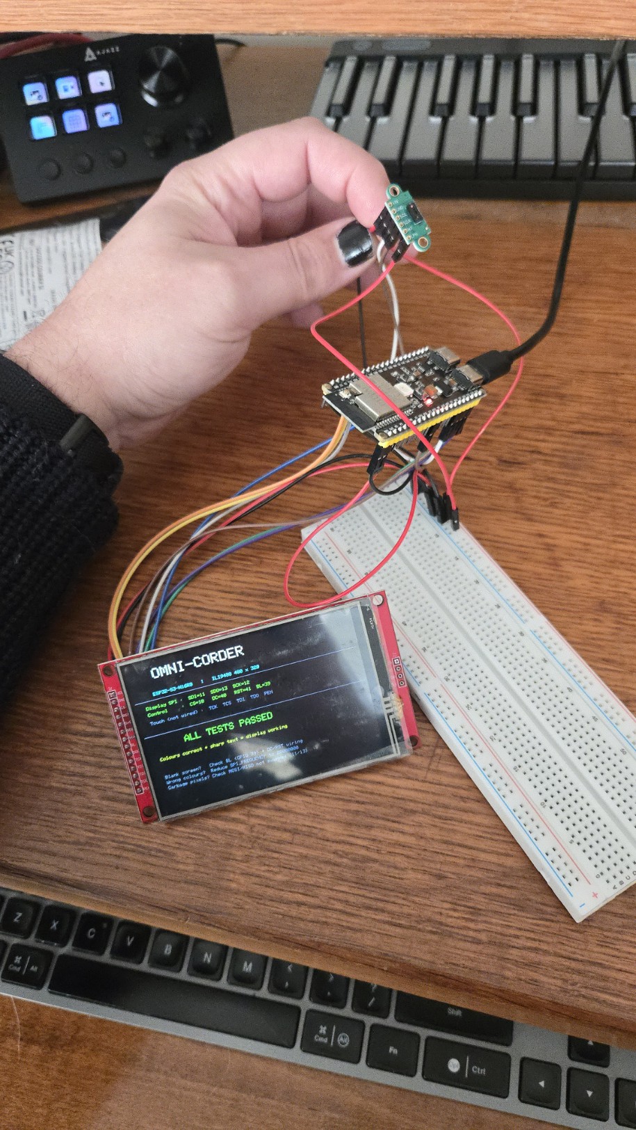
4. Crash inside tft.init() — TFT_eSPI defaulted to SPI3 (GPIO 35/36/37 area). GPIO 10–12 are on SPI2. Fixed with `-DUSE_HSPI_PORT` and `-DTFT_MISO=-1`.After resolving all four issues, the display worked correctly: full 480x320 colour, correct colours, no flickering.
![]()
ToF Sensor (VL53L5CX) bring-up
Wired VL53L5CX to I2C on GPIO 8/9. Added external 4.7 kOhm pull-ups on SDA and SCL.
Issues encountered:
5. VL53L5CX header not found — include path was wrong. Correct header is `SparkFun_VL53L5CX_Library.h` (not `_Arduino_Library.h`).
6. I2C Error -1 / sensor not responding — AliExpress breakout has no onboard pull-up resistors. Added 4.7 kOhm from SDA to 3.3 V and SCL to 3.3 V externally.
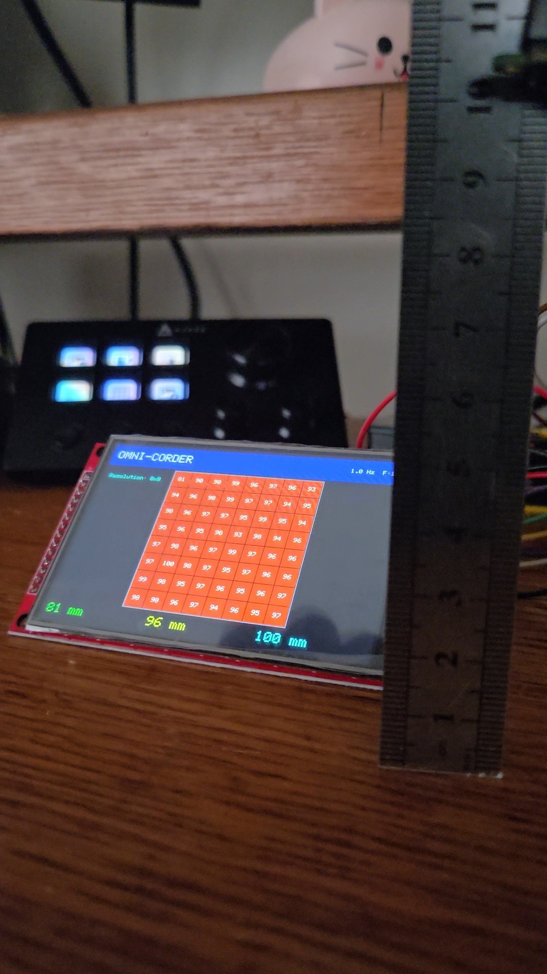
7. Sensor dots (retrying forever at startup) — LPN pin was floating. Wired LPN to 3.3 V. Sensor responds immediately after.After resolving issues, sensor confirmed working. Reads 8x8 depth array (64 values per frame) over I2C at address 0x29.
Accuracy test at 100 mm: sensor reads 96–100 mm (±4 mm).
![]()
![]()