Close
0%
0%

Accel-Lights for Inline

Reactive RGB LED lights for Inline Skates

mM
Similar projects worth following
Custom designed circuit board that attaches to aluminum inline skate frames to controll RGB LEDs for night time urban skating.

The LEDs are controlled by an Esp32 C3 with input from an 6 axis IMU to trigger changes to the light patterns as the user skates around.

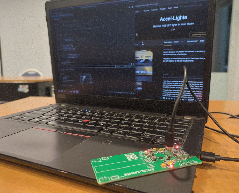
I was always somewhat disappointed with the commercial inline skate wheels, with built in LEDs that light up dimly as you roll around, due to the limits of the small built in dynamo. So I figured I could make something a bit more fun. Then it turned into a fun excuse to learn EasyEDA, then test JLCPCBs board assembly services for a prototype. 

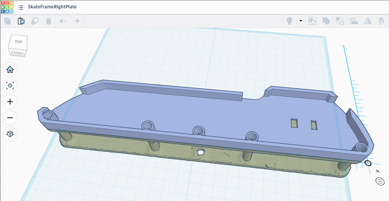
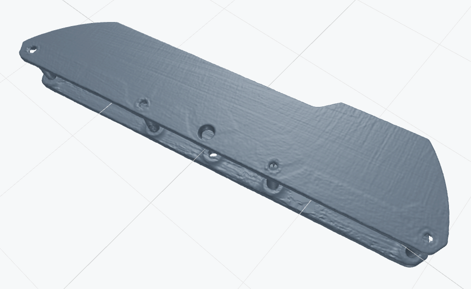
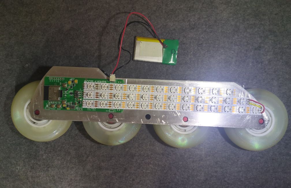
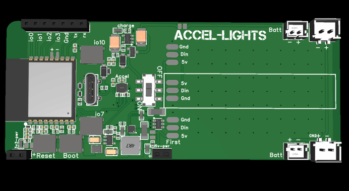
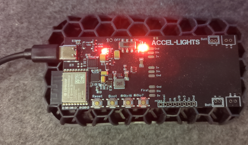
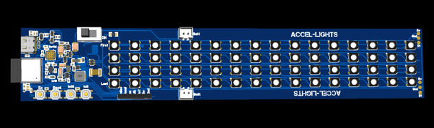
I thought about the project, then came away with a list of initial requirements I wanted to incorporate into the design. First, I wanted to integrate the lights to the skate frames and keep the profile low. I also wanted to add a built in rechargeable battery. I purchased some frames that had a flat profile so I could mount the the prototype board and LED strips. I then measured the width of the skate frames and put some thought into the layout to make the prototype mountable to either side with thermal adhesive tape. I also planned to add a 3D printed translucent outer shell to act as a light diffuser and environmental protection (dust, debris, water, etc.). I added an On/Off switch to save power. I added some push buttons so I could make changes to the patterns without needing to take out my phone.

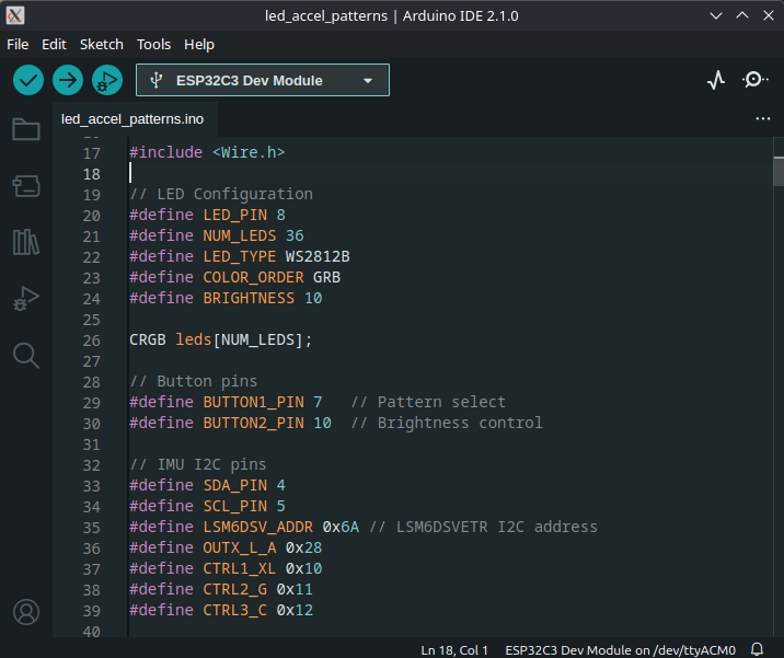
I later decided that the light patterns should react to my movements using an accelerometer. Each stride should trigger a pattern. I hope to trigger different patterns for skating styles (dancing, wizard, slalom). Using the various changes in directional acceleration as input will take some fine tuning.

  • 1 × Esp32 C3 Module Microcontroller
  • 1 × LSM6DSVETR IMU 6 Axis IMU
  • 40 × WS2812B LED RGB LEDs
  • 1 × SY8088IAAC Step Down
  • 1 × TPS61022RWUR PMIC 5v Step Up

View all 6 components

  • coding reactive LED patterns

    M3 hours ago 0 comments

    I'm at the point where I want to test what kind of patterns could look good on the skates. I have two basic patterns in mind that I've seen used in other projects, that just need to be adapted for a smaller LED array and to favor the Y axis to detect forward and reverse acceleration.

    I was initially going to hunt around for existing code in github repos to understand how they accomplished it, but decided to try to describe what I had in mind to a coding agent (OpenCode + GTP5.1 Codex). I first described the array and how the LEDs were numbered. I then described how to use thresholds of acceleration for the patterns. Then I did my best to described the patterns I had seen in the past. Surprisingly the agent was able to update my arduino test code which had all the pin assignments already defined. The output passed the build process. I loaded the code onto the first prototype with anticipation...

    It worked first try! I rolled the frame forward and backwards across my desk and the first pattern looked like what i expected. I then pressed one of the button to change to the second patter. Repeated the movement and while not exactly what wanted, it was pretty close.

    I know putting this code together would have taken me days, if not weeks with my meager embedded coding skills. Getting this project to a functional state just got a lot easier. I'm looking forward to exploring new possibilities with the help of an LLM.

  • Finding a battery for field testing

    M5 hours ago 0 comments

    For initial testing, I've been using an unlabeled battery from an conference badge I had lying around. It just happened to have the 2 pin JST PH 2mm female connector. I checked the polarity and voltage. Voltage was correct, but black was positive and red was negative. So I traced the wire to the battery protection circuit and it had the correct plus and minus symbols to back my findings. I charged it up and plugged it in... then it powered right up. Ran my test code without issue. I was a bit surprised, not sure why I was expecting something to fail.

    Since I don't want to rely on that old battery, I started to search for one online. I wanted something that would last a few hours, I decided to look for a 1500 mah, since I've seen plenty of lit up badges run off one for the day, so long as they aren't at max brightness. I started looking for a battery pack on Aliexpress. I have some size constraints for the little gap between the frame and boot. The frame is 34mm wide, the height of the gap is 10mm and length about 100mm. After looking for a reasonable priced 2 pack, I found a 3.7V 703450 Lithium Polymer Battery that had the appropriate JST PH connector. It had a protection circuit, so I decided to buy it and paid $13.73 with shipping. I should get the part in a little over a week.

  • Modeling a Faceplate

    M3 days ago 0 comments

    I took a shot at quickly modeling a faceplate using TinkerCAD using the 3D scan as a reference. I hadn't used it for some time, so I was pleasantly surprised to find that they incorporated a new sketch tool. This allowed me to roughly outline the side of the frame and extrude it. I added some holes and gaps to account for the switch and usb port. I now had a basic face plate to print.

    The library didn't have any slots, so I'll probably split this model in two parts so I can print it on my 3D printer. I'll post some pictures of the first face plate mounted to the frame. I just plan to use some double sided tape. Eventually I'll make someting that attaches more firmly with clips or something.

  • Frame Scan

    M4 days ago 0 comments

    I am planning to add an external face plate to the skate frames. It would attach to the outside of the frame and be removable. Its primary purpose is be a light diffuser for the RGB LEDs, but also protect the electronics from dirt and debris. My tolerances on the initial working prototype will be kind of loose, as I really just want to get out and skate with them to see how they'll hold up to some mild abuse.

    I was initially going to take some photos from above, adjust for lens skew, and outline the shape in Inkscape. So I could then extrude it in CAD and print a first iteration.

    Fortunately for me, I attended a local 3D print meetup and met someone who was showing off his 3D printed scanning table that he was using with his Creality RaptorX scanner. I hadn't considered 3D scanning, since my past experiences with scan quality were poor. I thought the reflective metal surface and anodization on the aluminum skate frames would be too much of challenge. But apparently these newer scanners are much better, as the scan quality was quite good and dimensionally accurate. It took a little effort to line up the point clouds from two separate scans and remove the noise, but the STL the software output was very good. 

    I decimated the model a bit further in MeshLab so I could import it into TinkerCAD that has a file size limit. 

    Since the dimensions of the frame are a bit larger than my 3D printers bed, I'm planning to go to my local library to print it. Most of the libraries in my area now have a Bambu Carbon X1 printers, so the print will fit on the large build plate diagonally, allowing me to print it as a single solid piece.

  • Right Frame Assembled for Testing

    M04/25/2026 at 05:25 0 comments

    Here is the board assembled and adhered to the skate frame.The battery pack lives in the gap between most boots mount points. I forgot to add thermal reliefs to the ground pads for the LED strips when I changed the layout of the board. I was also impatient and adhered the PCB to the frame with some thermal tape. So I had a hard time soldering the ground pads... hopefully there aren't any major cold solder joints that will break when I subject this to vibrations on the asphalt.

    Fortunately everything else is still working. It remains low profile. So now I just need to 3D print a translucent cover to act as a light diffuser and dust/debris protection. I'll eventually add a conformal coating, but I expect to need to make changes as I test this.

  • New board revision Working

    M04/23/2026 at 23:51 0 comments

    Got the new revision of the board in today. 

    I loaded up the Arduino IDE and attempted to connect to the esp32 via USB. After a quick check I verified the board appeared as a serial port. Since it was a new board without any code, it kept disconnecting and reconnecting. I held down the Boot button and then pressed the Reset button. This kept it in boot mode so I could load some code. I then downloaded the esp32 package through the boards manager and was able to select the ESP32C3 Dev Module as my board.

    I was able to use the Claude desktop client to generate some test code to verify the esp32 is working as expected. I checked the 2 button inputs. Then I tested that the RGB LEDs would light up. I was even able to scan for WiFi APs to verify wireless comms.

    Lastly I told it the model of IMU and it generated some code to find the I2C address, then figure out the I2C addresses I needed to plot and view the accelerometer and gyroscope data. I didn't have to open a data sheet for the IMU, which I hadn't used before this project.

    I'm going to move to the next step of partially assembling it to the frame and connecting the LED strips so I can test controlling the ws2812b LEDs.

  • New board revision

    M03/31/2026 at 01:39 0 comments

    I now have a new revision of the board on the way with several fixes and improvements. I adjusted the layout to make it more symmetrical, so it would work mounted on either edge.

    I moved the esp32 module to the center moved the antenna onto the board, then removed the copper from the top and bottom layer. I think this will better protect the board should an impact occur and the edge of the board is hit.

    I changed the IMU to one that is cheaper and more reliable. I haven't used an accelerometer in a project for many years. So I initially added the mpu6050 because I knew there was good arduino support. However, that increased the cost of my first prototype, then I later learned it was deprecated. So I switched to the LSM6DSV, since it was available in JLCPCB parts for economic assembly. I also read that this series of IMU was being used in other products, like the SlimeVR, so I made an assumption that I would not have any issues working with it.

    I changed and moved the USB port, so that it would be easier to access for charging/programming when mounted to the skate frames. The previous connector was difficult to access when I first mounted it to the frames.

    The On/Off switch was moved to the center so I could easily shut off the lights after a skate session.

    I removed the cp2102 usb bridge, since the esp32-C3 supports USB natively.

  • Recording data

    M03/30/2026 at 06:50 0 comments

    I want to record data from the 6 axis IMU (acceleromter + gyro) so I can profile different maneuvers while a person is skating around. I'm going to test using Edge Impulse to record data via WiFi using the ingestion api. I plan to use the motion recognition system ( https://docs.edgeimpulse.com/tutorials/end-to-end/motion-recognition ) by sampling the data over a few seconds to identify a maneuver, then trigger a specific pattern to highlight and compliment the move nicely.

    Would love to know if anyone has any suggestions on how best to accomplish this task once I finish assembling a working prototype. I'll start with testing the boards independently, but I'm sure the more interesting uses will involve input from both boards and them communicating.

  • First Prototype Failure

    M03/30/2026 at 06:19 0 comments

    Had some interesting twists and turns with this first prototype.

    First mistake was a result of my trying to save some money on tariffs. Wanting to take advantage of my proximity to a border with another country, I had the boards shipped to a friends address across the border. This resulted in some issues with the last mile shipping company having some issues locating the address and it going back and forth in their system, which resulted in me waiting about an additional month to receive the boards.

    My next problem was a result of me probably connecting something incorrectly to the usb bridge in the schematic, so the board would get power when connected to USB (type C), but would not appear in the system. It appears there cp2102 usb bridge was in a bad state, since the voltage on D+ was about 1.6v.

    I later found a more experienced board developer on Fiverr to review my schematic and layout, where he identified a few issues I needed to correct. 

  • RGB LED components

    M03/30/2026 at 05:57 0 comments

    I initially planned to have a longer board the length of the skate frame and add the RGB LEDs onto the board, but supplies for RGB LEDs that were available for Economic assembly ran out in December, as I imagine people were creating their own fun LED projects for the holidays. This forced me to rethink my plan. I then decided to add pads to the board so I could solder LED strips that I could then adhere to the frame and cut to length. I think this came out to be a better solution, since I can accommodate different frame lengths in the future. As a result I don't have to worry about getting the component packages baked during the production process to remove humidity, as I later learned these components absorb moisture and are sensitive to the heat changes, causing them to regularly fail. The smaller board size (less than 100mm x 100mm) resulted in a much cheaper board as well.

View all 10 project logs

Enjoy this project?

Share

Discussions

Phil Weasel wrote 04/02/2026 at 13:20 point

Oh my god, this is awesome. Im so looking forward to see this in action. Please please please  make a video 🙏

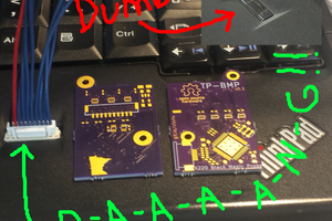
Also: i have some bad experience on using those connectors (if i see correctl from the footprint) in such a vibration-heavy environments. Maybe have a look to the JST-JWPF series. They are sealed and thus have a bit more protection when a wire breaks off the crimp. Last thing you want is a shorted battery attached to your leg.

  Are you sure? yes | no

M wrote 04/02/2026 at 17:47 point

Hi. Thanks for the comment. Will definitely record a video and add more pictures once I get it assembled and somewhat working with the next revision. 

I appreciate you sharing your experience with the jst connectors. I definitely added the footprint to the corners, so I would have the option, but will see once I get to "field testing". I've also had the connector fail with intermittent power loss in situations with vibrations, but not had it short. I previously solved it with some strategic dabs of hot glue. I still have the option to solder the wire leads directly to the board should it prove to be a problem. I'll make sure to wrap the battery in a few layers of insulation and kapton tape for a worst case scenario.

  Are you sure? yes | no

Similar Projects

Does this project spark your interest?

Become a member to follow this project and never miss any updates