 Marco Tabini
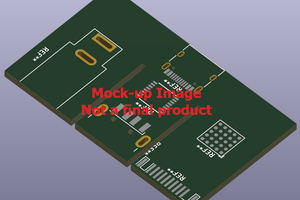
Dr. PD is an open-source USB-C Power Delivery analyzer and programmable sink. It can sit inline between a USB-PD source and sink to show you the communication between them, or connect directly to a source and emulate a sink so you can characterize chargers and power supplies.
The goal of the project is to make serious USB-PD analysis more accessible. The hardware, firmware, and host software are all open source. The control software runs locally in Chrome or Edge with no drivers or installation required, and the platform also provides Python, JavaScript, SCPI, and USBTMC interfaces for automation.
Want your own? Dr. PD will be crowdfunding soon. Follow the project page on Crowd Supply and sign up for updates!
What it does
-
Captures and decodes USB Power Delivery traffic in real time
Measures and plots VBUS voltage and current alongside protocol events
-
Correlates PD messages with live power behavior
-
Supports SPR, EPR, PPS, and AVS modes up to 48 V / 5 A / 240 W
-
Acts as a programmable sink for source characterization and fault injection
-
Provides triggering, search, annotation, and export tools for long captures
-
Works with a browser-based UI, terminal tools, and industry-standard automation libraries (USBTMC, SCPI, Python)
Why it exists
USB-C Power Delivery is powerful, but debugging it is often painful. The chips used to add USB-PD support to products usually expose very little about what is happening internally. Many power supplies also support capabilities beyond what common interface chips make easy to access, and characterizing source behavior, especially with battery-powered supplies, can be difficult.
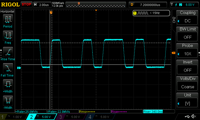
The usual alternatives are either sniffing traffic with an oscilloscope or logic analyzer, or using a dedicated USB-PD analyzer. The first approach is fiddly and makes it hard to correlate protocol activity with analog behavior like voltage and current. The second often means buying tools that cost hundreds or thousands of dollars.
Dr. PD is meant to fill that gap by providing professional-grade USB-PD analysis in a fully open-source instrument that is capable, transparent, repairable, and free from proprietary lock-in.
Highlights
-
Inline USB-C analysis with synchronized power measurements
-
Programmable sink mode for charger and source testing
-
Support for modern USB-PD revisions, including EPR
-
Browser-based control software with no installation required
-
Automation-friendly interfaces including SCPI, USBTMC, Python, and JavaScript
-
Open-source hardware, firmware, and software
Current status
Dr. PD is currently at the DVT stage. The hardware and software are working, and the system is now undergoing testing and verification. Follow the project for updates as the design progresses and we start sharing demos, and don't forget to sign up for our upcoming crowdfunding campaign!
 Torbjörn Lindholm
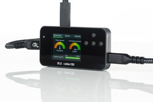
 Nick Sayer
 even_notodd