Charlie Theobald
-
22nd May 2026 - Comparing / verifying two master VCOs
05/17/2026 at 00:24 • 0 commentsI've watched Eurovision every year for the past 10 years or so - this is probably the first time in the contest's history that an analog synth designer has performed on stage. A little disappointed that crazy British synth man didn't do so well this year, but it's been nice to hear murmurs of synths and vintage electronics in the news and I hope it's inspired some people.
This week
This week has been less productive than I thought it'd be, as I've found most of my time being consumed by our university group project.
I've still been able to work for a couple of hours each evening at home, and have been focusing on breadboarding both the Korg Lambda and Roland RS-505 Paraphonic master clock generators, and building up the MIDI to CV converter which will become a significant point of focus over the next few weeks.
Many pictures this week and less theory :)
![]()
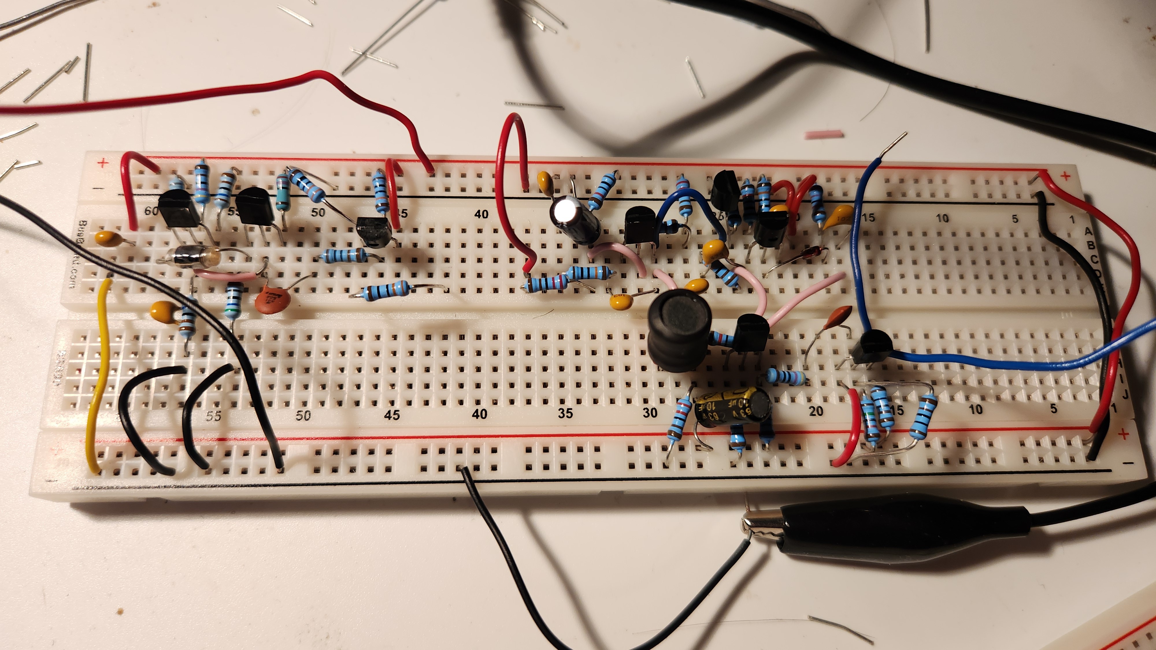
The Lambda master VCO is on the left, and the Paraphonic's is on the right. Notice how many more components are required for the Paraphonic. ![]()
I've found it helpful to store pdf versions of the schematics on my tablet, highlighting as I connect the components. Mistakes are less likely, and it's immediately obvious which parts still need connecting after a break. So...which VCO is better?
My main concern in last week's update was the compromise between the large rise-time caused by the Lambda's first-order feedback, and the possible increased parasitics of the Paraphonic's second-order feedback.
I had a suspicion that the Paraphonic's master VCO would be better performing, as the Lambda was designed as a budget synthesizer at the time of its release, but also questioned whether first-order feedback could be a better design choice. Over the past week, I've examined both circuits with the oscilloscope to get a real-world comparison, and the results are worth analysing.
![]()
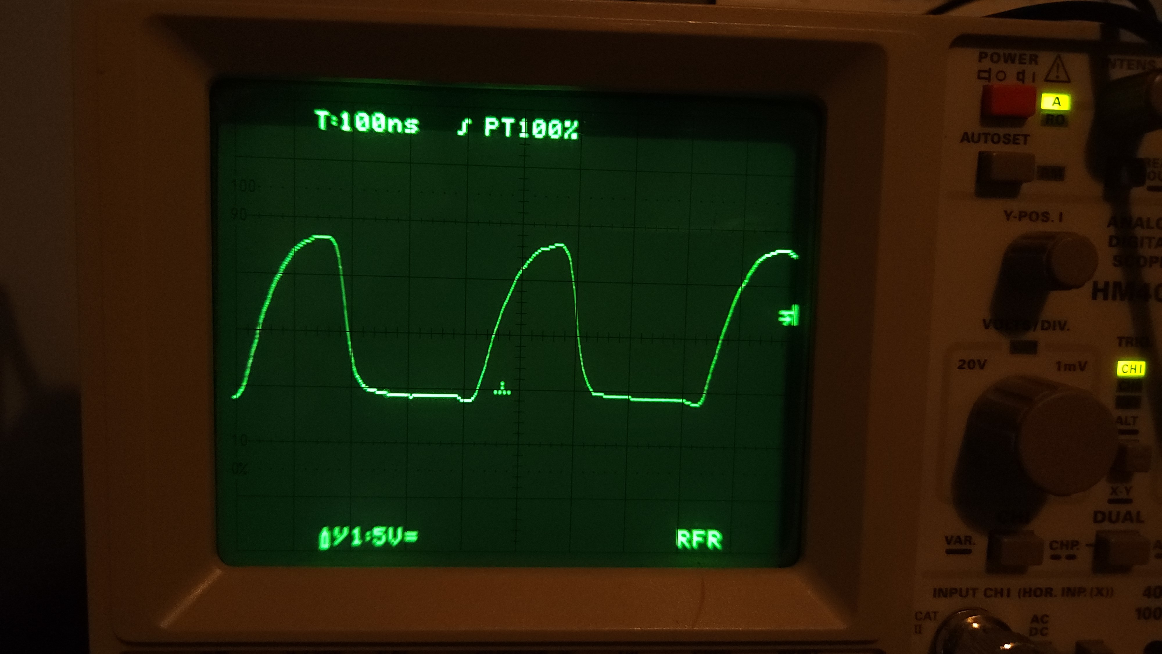
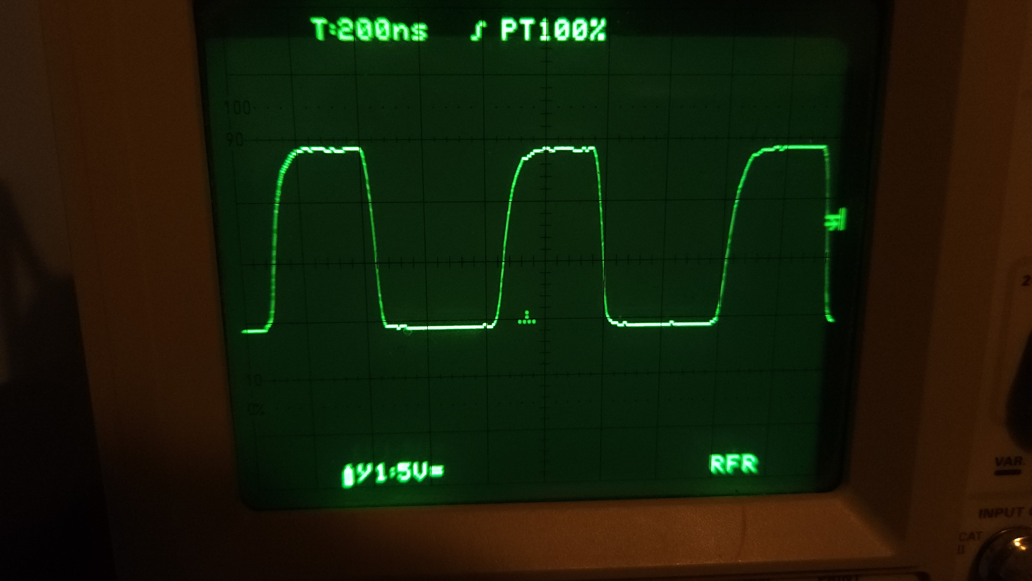
Output of the Korg Lambda master VCO This is the output of the Lambda's master VCO. The first-order charging and discharging of the 120pF capacitor is very obvious on the waveform, and the rise-time is close to our estimate, at around 120ns by inspection. Interestingly, I found that when the output resistors R9/R10 were left at 3.3kΩ, the output appeared more like a low-amplitude triangle wave. Therefore, I decreased R9/R10 by a factor of 10 to 330Ω, increasing the quiescent output voltage of Q1, and this seemed to do the job. I still need to play around with different values of R9/R10 that give the best results.
This VCO really impressed me with its fantastic frequency stability. Despite having a much less complicated negative feedback than the Paraphonic, the oscillation never varied by more than 8000Hz from its average frequency of 2.420MHz. That's a 0.3% maximum error, with standard deviation 0.2%! To put this into perspective, if the oscillator was tuned to A = 440Hz, then the oscillator's frequency would never go below 438.5Hz or above 441.5Hz. A perceptible difference, but much better than I was expecting, especially for a breadboard and my questionable wiring.
Undoubtedly a good design; the only thing letting it down is the clock rise time.
![]()
Output of the Roland Paraphonic master VCO ...and here is the Paraphonic's master VCO output. I've supplied it at Vcc = +15V and Vee = 0V for simplicity in this picture, different from the negative power supply rail used in the original design. Everything else is unchanged, except for the lack of a varactor diode used for precise frequency trimming which doesn't really affect the behaviour or stability.
The rise time is much less than the Lambda, at around 40ns, which makes it more attractive for feeding into the clock dividers of the top-octave generator to follow. If you look closely, the ringing caused by second-order effects is definitely there, but it's very well controlled and small compared to the oscillation amplitude. I made sure to use a film capacitor in the LC tank instead of a ceramic one to try and help with this.
The frequency stability is also equally excellent - I didn't have the opportunity to measure it directly using proper equipment in the lab at college, but it's very comparable if not slightly better than the Lambda.
The only disadvantage of this circuit is its complexity - it uses significantly more components than the Lambda's VCO, and analysis / troubleshooting is much more complicated.
In my master VCO design, I'd like to use the LC tank from the Paraphonic for its faster rise time, and the simpler negative feedback of the Lambda to reduce component count and complexity. Over the weekend I'll finalise my design and confirm it performs as expected.
How can we interface the master clock to the rest of the VCO?
As previously mentioned, the master VCO will feed into a top-octave generator, generating all 12 notes on the highest octave of the keyboard, followed by binary dividers to generate all notes in lower octaves.
Our top-octave generator, the M082B1, uses integer division of the master clock by precise factors to obtain all the notes of the highest notes on the keyboard.
Application information from the M082B1 top-octave generator datasheet For example, to obtain a C# from our master clock generator (the lowest note in the top octave), the top octave generator divides our clock frequency by 451. In order for the sounding pitch of this note to actually be C#, we must precisely tune the frequency of our oscillator to a multiple of 99680Hz. This is a weird frequency, but I think it's specifically been chosen so that the integer division very closely approximates the true ratios between pitches.
I avoided talking about this until now, but both the Lambda and Paraphonic both have a DC voltage bias input which can be used to finely vary the frequency of our master VCO. This voltage can be set precisely to DC creating a fixed oscillation frequency, or modulated to create vibrato effects.
This is another reason why these analog clock generators were used, instead of a crystal oscillator which cannot change its oscillation frequency at all. The existence of this DC bias may also allow us to implement a phase-locked loop architecture in the future if we're feeling very fancy.
I must admit, over the past week I haven't had much opportunity to experiment with tuning or integrating with the TOGs due to time, this is definitely a task for over the weekend, and I'll report back on the success of this in next week's update, where if we're lucky we might be able to get some sound.
The VCO deadline is fast approaching
My current deadline for completing the VCO is on the 31st May, just over a week from now. I'm confident we can get a working prototype for the full VCO before this date, though I'm not sure a PCB will be ready in time.
A lot of work with the VCO will also link nicely into my next deadline (14th June), where I integrate the VCO with keyboard control through our MIDI to CV converter (currently under construction)!
-
15th May 2026 - Let's Make Stuff! Choosing a VCO architecture
05/14/2026 at 00:26 • 0 commentsMy last few exams went considerably better than the three exams I had before the last update. I might actually pass the year.
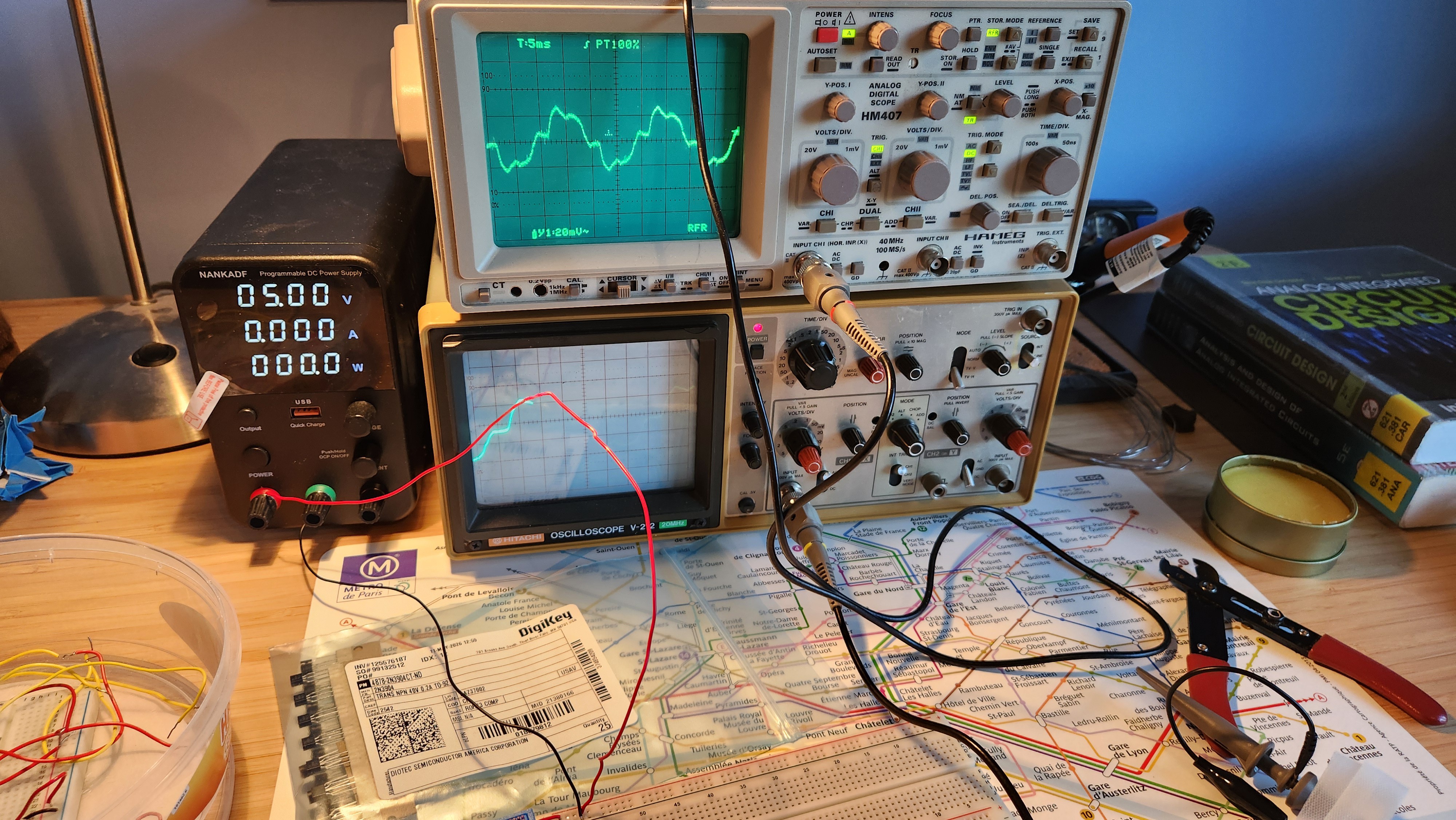
As of Tuesday all my exams are finished, which means I have much more time on my hands, and have been able to start building my home electronics lab.
![]()
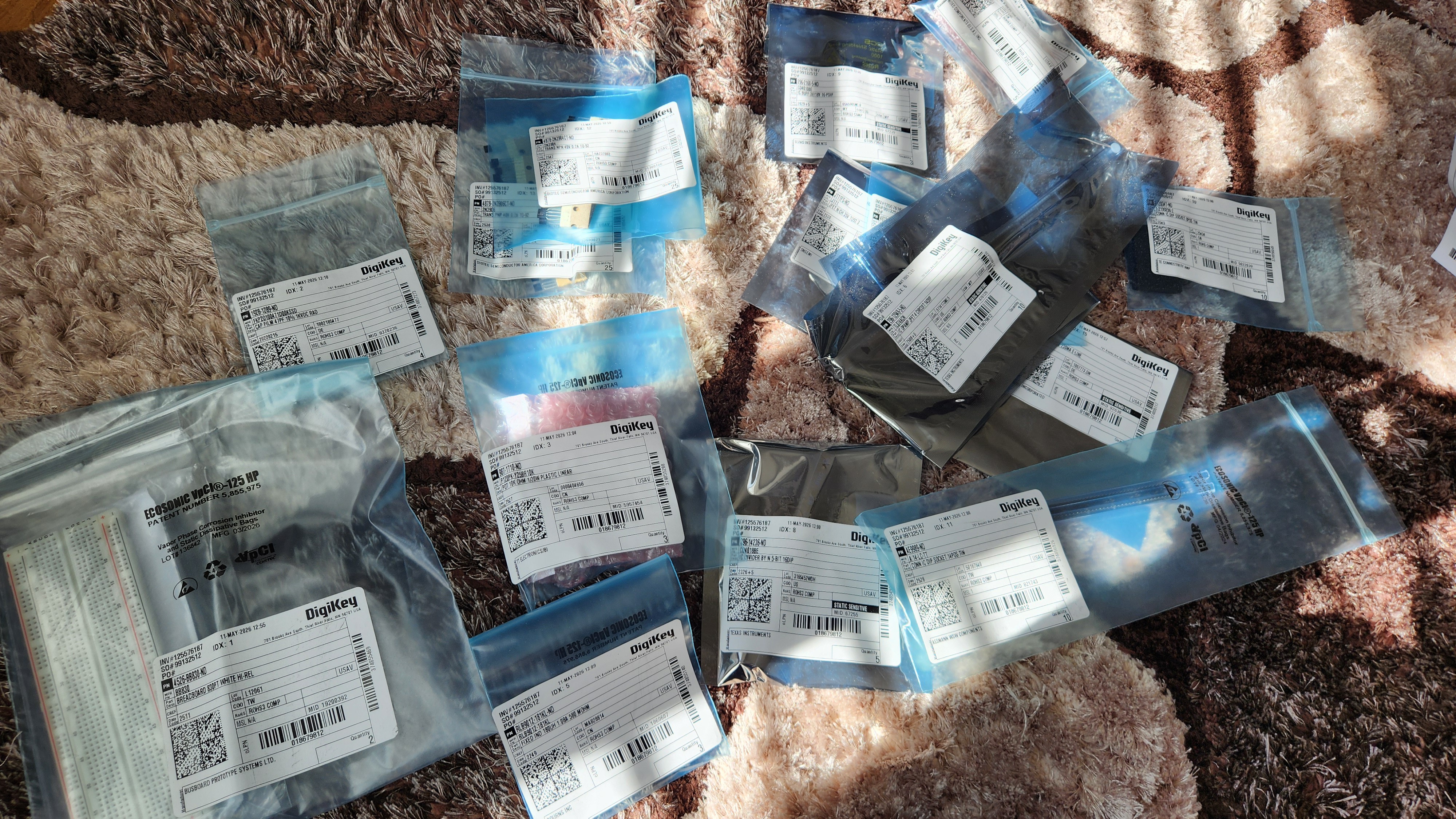
It couldn't be any better timing; a large order from DigiKey arrived on Wednesday and another from Retroamplis on Thursday. Before we start talking about oscillator architectures, I'll list everything that came through the post this week for recordkeeping sake.
In the post
BB830 solderless breadboard x2 £13.26 47pF film capacitor x4 £1.88 10K rotary pot x3 £3.15 100K trim pot x4 £3.45 180uH inductor x3 £1.38 TL074 quad JFET op-amp 14DIP x10 £5.99 J111 n-channel JFET x5 £1.70 CD4018BE 5-bit divider by N 16DIP x5 £4.70 CD4010BE buffer 16DIP x3 £1.92 8DIP IC sockets x10 £1.50 14DIP IC sockets x10 £1.42 2N3904 NPN transistor x25 £1.63 2N3906 complementary PNP transistor x25 £1.63 2N7000 n-channel MOSFET x10 £1.33 BS250P p-channel MOSFET x5 £5.65 M082AB1 13-note Top Octave Generator 16DIP x4 £35.81 This is a total expenditure of £86.40, bringing the total spend so far up to £129.25. This is a very significant order, and will probably be one of the largest of the whole project.
![]()
Choosing a VCO architecture
There are many different VCO architectures used in synths from the valve era right through to the present day. For musical use, they must all be of excellent accuracy to reproduce pitches well, no matter the temperature, environmental noise or any other initial conditions.
Phase-shift oscillator
An oscillator, in its simplest form, is an amplifier with gain greater than 1, and a feedback network providing an overall phase shift of 360 degrees (such that the feedback signal superposes with itself). This is a necessary, but not sufficient, condition for oscillation known as the Barkhausen stability criterion.
![]()
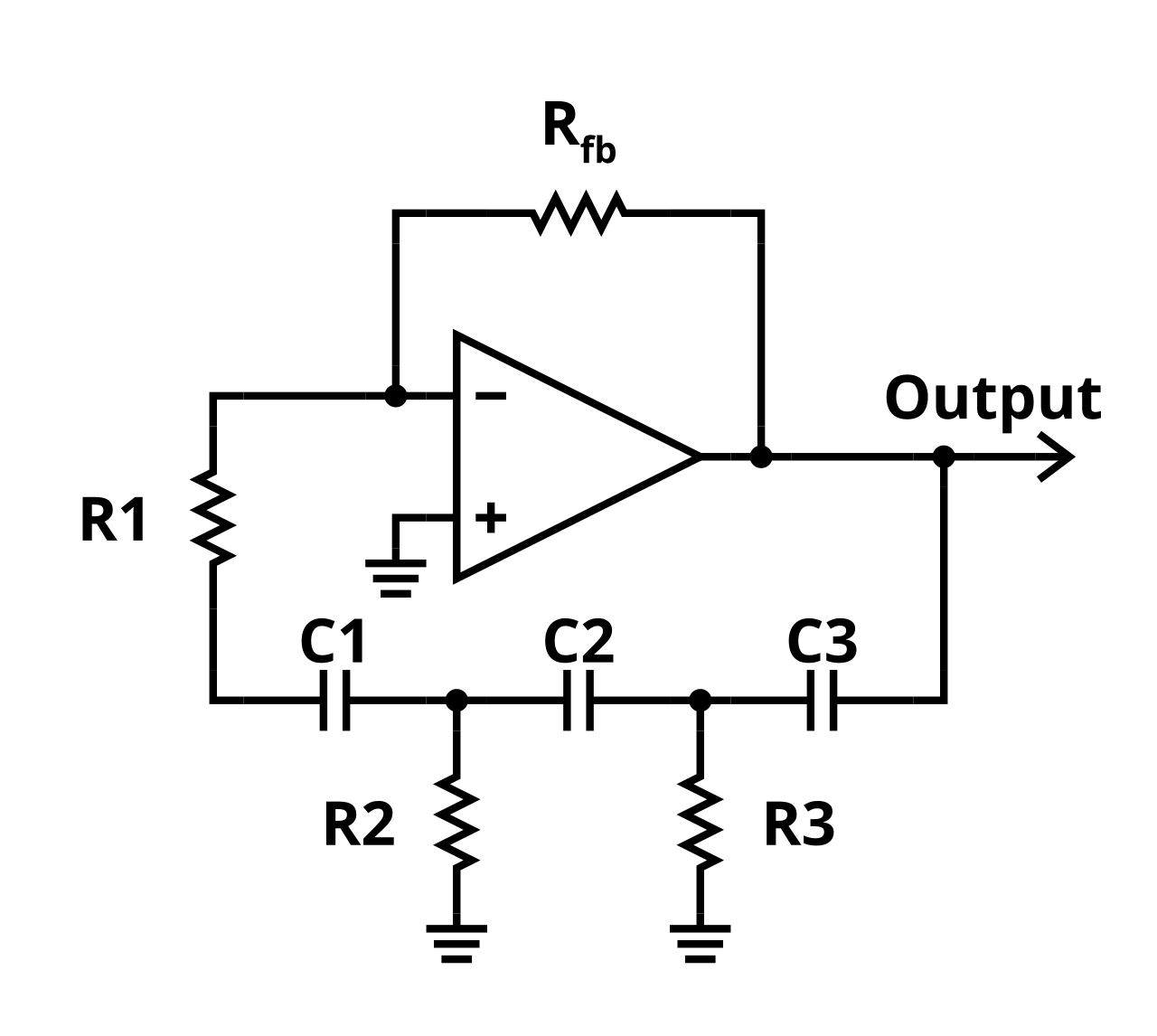
By Ea91b3dd - Ozhiker, CC BY-SA 3.0, https://commons.wikimedia.org/w/index.php?curid=17055611 Above is a schematic of a simple phase-shift oscillator. In the example above, the three RC stages provide a combined 180 degrees of phase shift, and the op-amp adds another 180 degrees of phase shift at the output as the signal is fed into the inverting input.
The circuit produces a sinusoidal output voltage, with frequency of oscillation is given by
There are a couple of problems with this circuit that make it unsuitable for use in our synthesizer.
- The op-amp output will either grow or shrink exponentially unless the feedback resistor R_fb is set to an exact value. As our op-amp supply rails are limited, significant distortion may occur if the signal grows and clips at the rails, or worse the output voltage collapses as the closed-loop gain becomes less than 1.
- The output is a pure sine wave. Analog synthesizers use the principle of subtractive synthesis. This means that they start with a harmonically rich sound like a sawtooth, square or triangle wave, and shape the sound using VCFs and tone filters. A pure sine wave has no harmonics, so we cannot tailor the sound to our liking.
- Voltage control of the oscillator is challenging, as we need to simultaneously modify the feedback network whilst ensuring the open-loop gain remains 1. This means it's not suitable for varying frequency.
(N.B a technique called additive synthesis also exists, where sounds are synthesized by summing sinusoidal waveforms together. As many fundamental waveforms require infinite sums of sinusoidal waveforms, additive synthesis uses a lot of hardware very quickly.)
A circuit like this may be useful for low-frequency modulation at a fixed frequency such as tremolo / vibrato, but we need to continue our search to find something better.
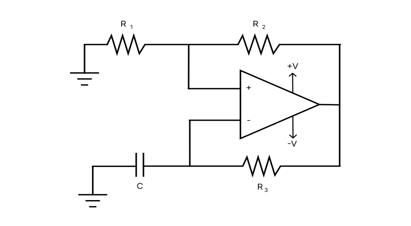
Relaxation oscillator![Relaxation Oscillator Calculator - Stompbox Electronics]() The relaxation oscillator is one of the most commonly used oscillators for producing square and triangle waves. It takes the form of an op-amp configured as a Schmitt trigger, which is a type of comparator with two voltage thresholds determined by the output voltage, R1 and R2, plus an RC discharge network (R3 and C) which creates a periodic oscillation. The relaxation oscillator is the working principle behind the legendary NE555 timer chip.
The relaxation oscillator is one of the most commonly used oscillators for producing square and triangle waves. It takes the form of an op-amp configured as a Schmitt trigger, which is a type of comparator with two voltage thresholds determined by the output voltage, R1 and R2, plus an RC discharge network (R3 and C) which creates a periodic oscillation. The relaxation oscillator is the working principle behind the legendary NE555 timer chip.The output of this circuit will be a square wave as the Schmitt trigger flips between its two output states, with the voltage across the capacitor being a passable approximation of a triangle wave. Voltage control of the frequency is now much more easily implemented, as we can vary the frequency simply by changing R3 (or indeed C, though variable resistance is much more common).
This circuit is simple and solves some of the issues with the phase-shift oscillator, but is still not fantastic.
- The oscillator is quite unstable in frequency as it lacks any real negative feedback to preserve the resonant frequency.
- In an op-amp implementation, the maximum frequency of the oscillator is limited by its slew rate and bandwidth
- The oscillation is created by an RC network, which creates significant "rounding" as the capacitor takes time to charge, especially for low frequencies.
The relaxation oscillator is commonly used in things like alarms or extremely cheap audio equipment, that sort of just needs to make a sound or oscillate; where frequency stability or bandwidth isn't really that important. They are rarely used in synthesizers or applications where stability is important.
If we're staying true to the 1970s/80s, fast and precise op-amps were not nearly as widespread as they are now. Discrete transistors were more frequently used as they have much faster switching speeds. After turning to schematics from synth service manuals of the period for some inspiration, there's one particular type of oscillator that caught my interest.
The clock-divider VCO (or DCO)
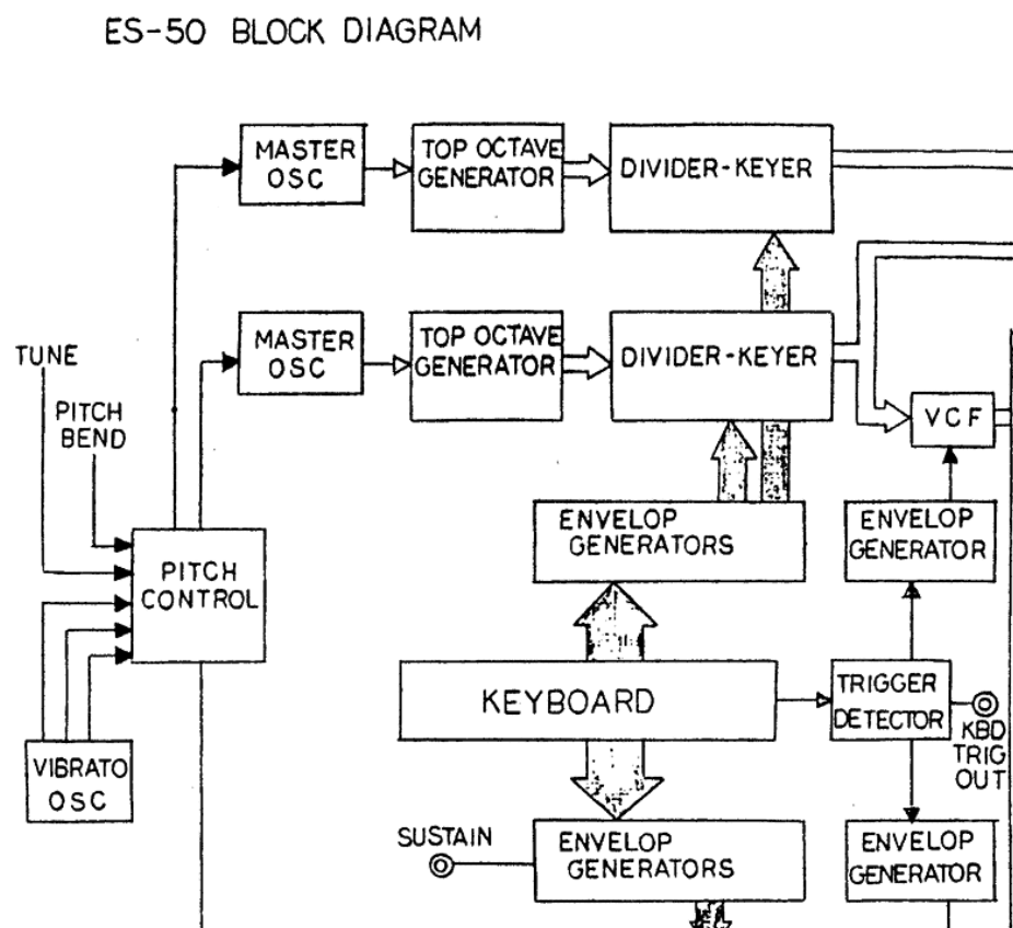
The clock-divider oscillator uses an extremely stable master oscillator that generates a clock signal, typically in the MHz range. This is fed into a specialised chip known as a top octave generator (TOG) that divides this clock signal by an integer to obtain the "top octave" of the keyboard. This signal is then fed through a divider-keyer, which is effectively a set of divide-by-2 flipflops, to generate all octaves on the piano keyboard.
This is exactly how many late 70s/early 80s polyphonic synths generated their waveforms.
![]()
This architecture is significantly more complex, and blurs the boundary between analog and digital, but it is significantly more robust and frequency stable than free-running oscillators (like the phase-shift and relaxation oscillator). Some synth enthusiasts would argue that clock-divider VCOs are so precise they feel almost clinical, as they lack the "analog imperfections" of slight phase and frequency variations between notes. But my engineering brain tells me that it's always better to create something stable first then introduce controlled instability later, rather than settling for something suboptimal due to previous design choices.
One advantage of the clock-divider architecture is that because all notes on the keyboard are derived from the same clock, even if the master clock drifts slightly, the notes in a chord should always sound in tune relative to one another. Polyphony is also very easy to implement, as a single top-octave generator and divider-keyer can, and does, supply the frequency to every note on the keyboard. The only limitation to polyphony is the frequency of MIDI note events.
The most challenging part of the VCO design will be the master clock generator design. How can we design an accurate clock generator that meets our frequency stability requirement of 0.1%? Let's turn to two example designs for inspiration, one which I believe might be better than the other.
Evaluating clock generator designs
![]()
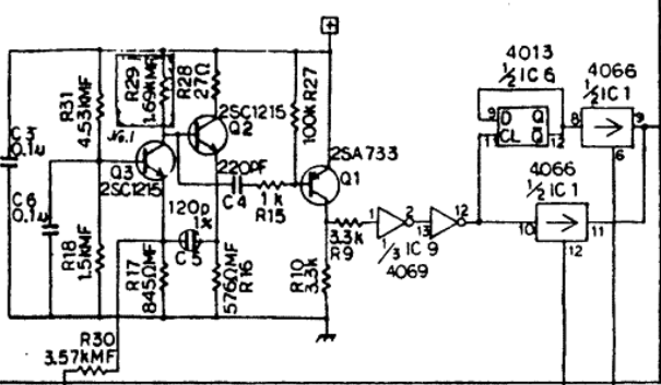
This is the master clock generator / oscillator from the Korg Lambda ES-50, released in 1979. The Lambda was considered a budget synth at the time of its release, so the electronics might be skimping a bit compared to Korg's cream of the crop (don't get me wrong, it's not a bad synth by any stretch of the imagination!)
While it looks a little complicated, analysis based on the Barkhausen criterion mentioned earlier simplifies the analysis a lot.
- This oscillator is centred on transistors Q3 and Q2, which are both configured as common-emitter amplifiers. As collector voltage of a CE amplifier is 180 degrees out of phase with the base voltage, the total phase shift in the loop is 360 degrees with a resonant frequency determined by C5 and R16. This satisfies the Barkhausen criterion.
- Transistor Q1 is a PNP transistor configured as an analog buffer, creating additional stability.
- C3 and C6 I believe are decoupling capacitors. Whilst they do slightly influence the resonant frequency of the oscillator, I don't think they're meant to.
The result is a near square wave at the collector of Q1. As the oscillator runs at quite a high frequency, despite C5 being tiny its rise time is likely to be significant. A quick check using the rise time approximation of a first order system gives t_r = 2.2RC = 150ns, which for the oscillation frequency of 2.3MHz makes up around 70% of the square wave on-time.
Is this acceptable? I'm not sure, and I suppose this is the purpose of the 4069 buffer after R9 to sharpen up the clock edges, but from my simulation the 4069 doesn't appear to have much effect, at least from a signal integrity perspective. Long rise times are generally bad for flip-flops as it increases the chance of them entering a metastable state during state changes.
On the other hand, as the oscillation is first-order, there will be no overshoot, undershoot or ringing of the clock, which is good. This could be a design compromise to prevent this from happening.
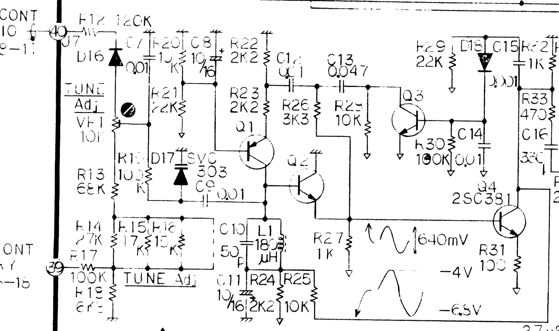
![]()
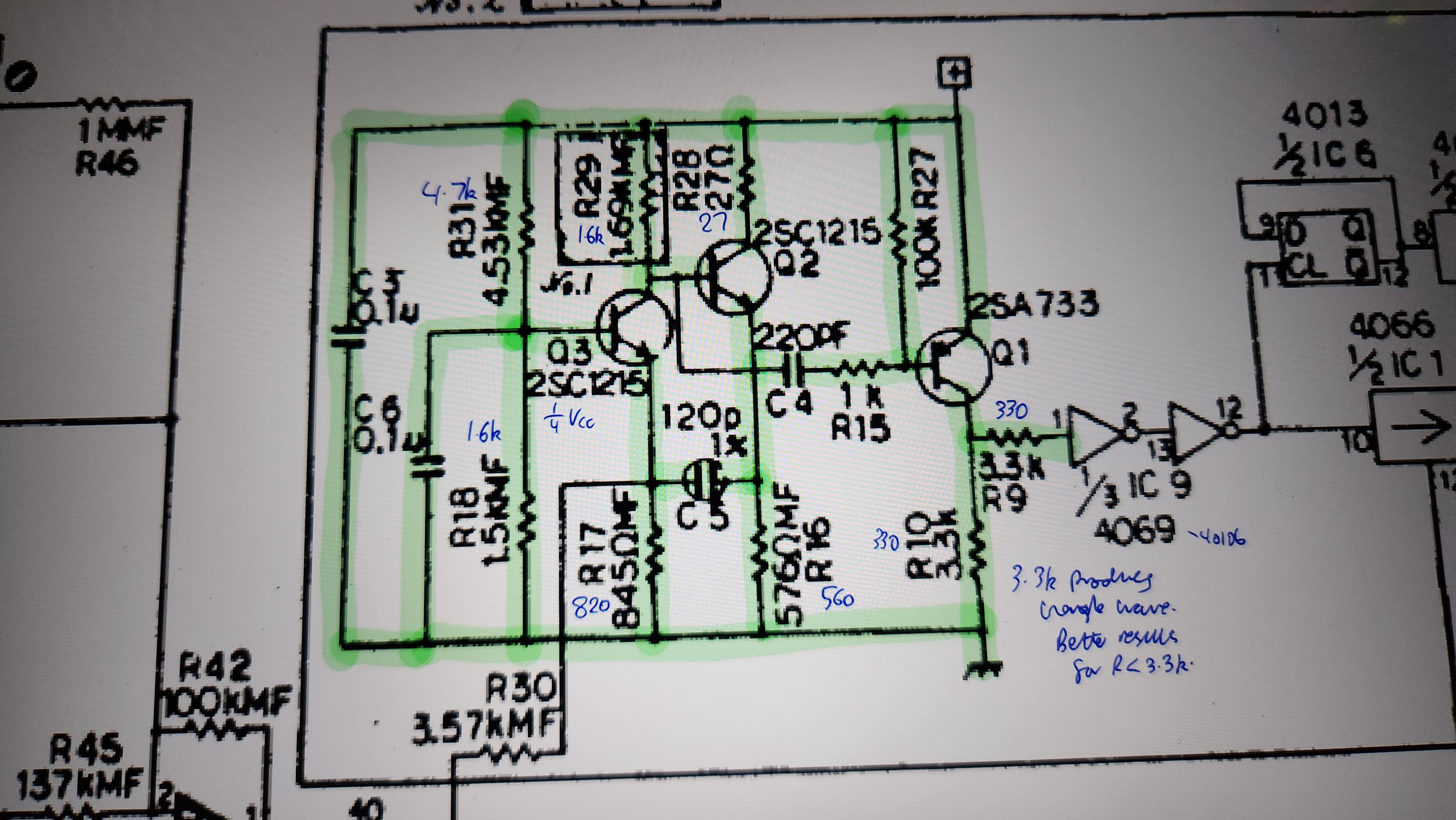
This is the master clock generator from the Roland Paraphonic RS-505, released in 1978 at a similar time to the Lambda. This was a high-end string machine, and has the design to back up the price tag. I must admit I don't completely understand this design yet, however it's clear this uses a second-order LC resonator made up of C10 and L1 and a much more complicated feedback network. As previously remarked in an earlier update, this synth uses 0V as the positive supply rail and -15V as the negative supply rail, supposedly also to improve stability by reduced electromagnetic effects.
For my master VCO, I'd like to take inspiration from both these designs, and form a Franken-VCO that interfaces well with the digital stages.
Next week, I'd like to construct these circuits and conduct a detailed real-world analysis of this circuit on a breadboard - if these circuits achieve good stability on the breadboard, they should still be reliable on a well-designed PCB, which I'd like to get sent off by the end of the month.
(Sorry, I lied about this being a purely analog synthesizer. Nevertheless, it's happening!)
-
1st May 2026 - Project plan (and some post through my letterbox)
05/02/2026 at 19:43 • 0 commentsAs predicted, none of the exams I've had this week went particularly well. But maybe I'll surprise myself like last year when results come out.
This week
Not much progress this week due to exams. As mentioned in last week's update, I hope to start building from around mid-May.
When I haven't been in Laplace transform jail, this week I've been thinking about project timelines and also about possible designs for my VCO. I'll start with discussing project timelines first.
Project stage Things to do Deadline VCO and oscillator core Decide on oscillator type, design wave generator circuits, prototype on breadboards, design PCBs, test initial prototype 31st May MIDI control integration Linking the VCO to a MIDI source, implement polyphony 14th June Design of envelope generator, VCA and VCF Decide on VCA/VCF types, decide between analog / digital implementations, prototype on breadboards, design PCBs, test initial prototype 11th July Buffer period for integration testing / parts delay Combining VCO, VCA and VCF designs to work effectively together, analysis of noise performance, hopefully prototype design PCBs have arrived 31st July Improving stability Adding improved power supply and temperature compensation for more advanced features later mid Aug "Nice-to-haves" Noise generator, LFO, sample and hold, frequency modulated / sync VCOs Sep If I can get to having a good VCO, VCF and VCA by the end of July, I'll be happy, as this will give me a solid two months to add interesting improvements. I have an assessed university project from May-June, and an internship during July, both of which should come first, so I've given extra time to some of the earlier deadlines.
This plan almost definitely will change during the course of the project. This is my first build at this scale, and my first time making a synthesizer, so I'm prepared to anticipate and embrace delays.
In the post
![]()
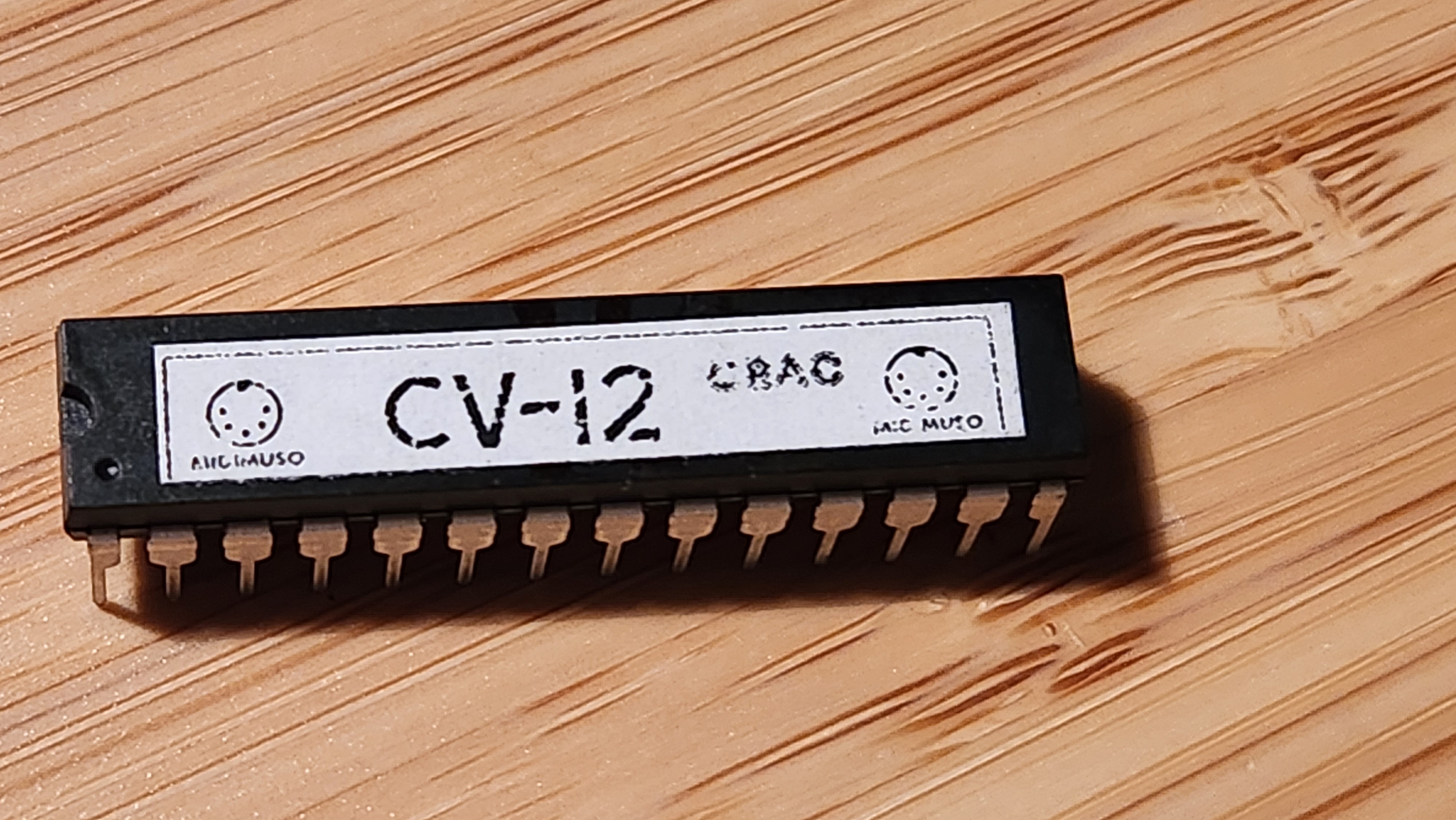
CV-12 ORAC chip from Midimuso (£17.49 as part of a kit containing a PCB and other components) The CV-12 is a remarkable chip, which is capable of converting digital MIDI signals into a CV (control voltage) and a trigger (a short pulse that tells an envelope generator / amplifier when a MIDI Note On event is detected).
Many MIDI to CV/Trig converters are very expensive, with good ones costing around £100 each. These are intended more for the Eurorack market rather than for ground-up electronics builds, so don't really fit my requirements or budget.
What makes the CV-12 special is that it is capable of polyphonic MIDI to CV conversion, meaning it is capable of outputting many control voltages (corresponding to many different notes) at once. This means it becomes possible to play chords from the get-go. It's also fully configurable with various mode changes. Polyphony can be sacrificed for additional MIDI parameters like note pressure and pitch bend, and even VCF parameters like cutoff / resonance. Considering what this thing can do, £17 is an absolute bargain.
![]()
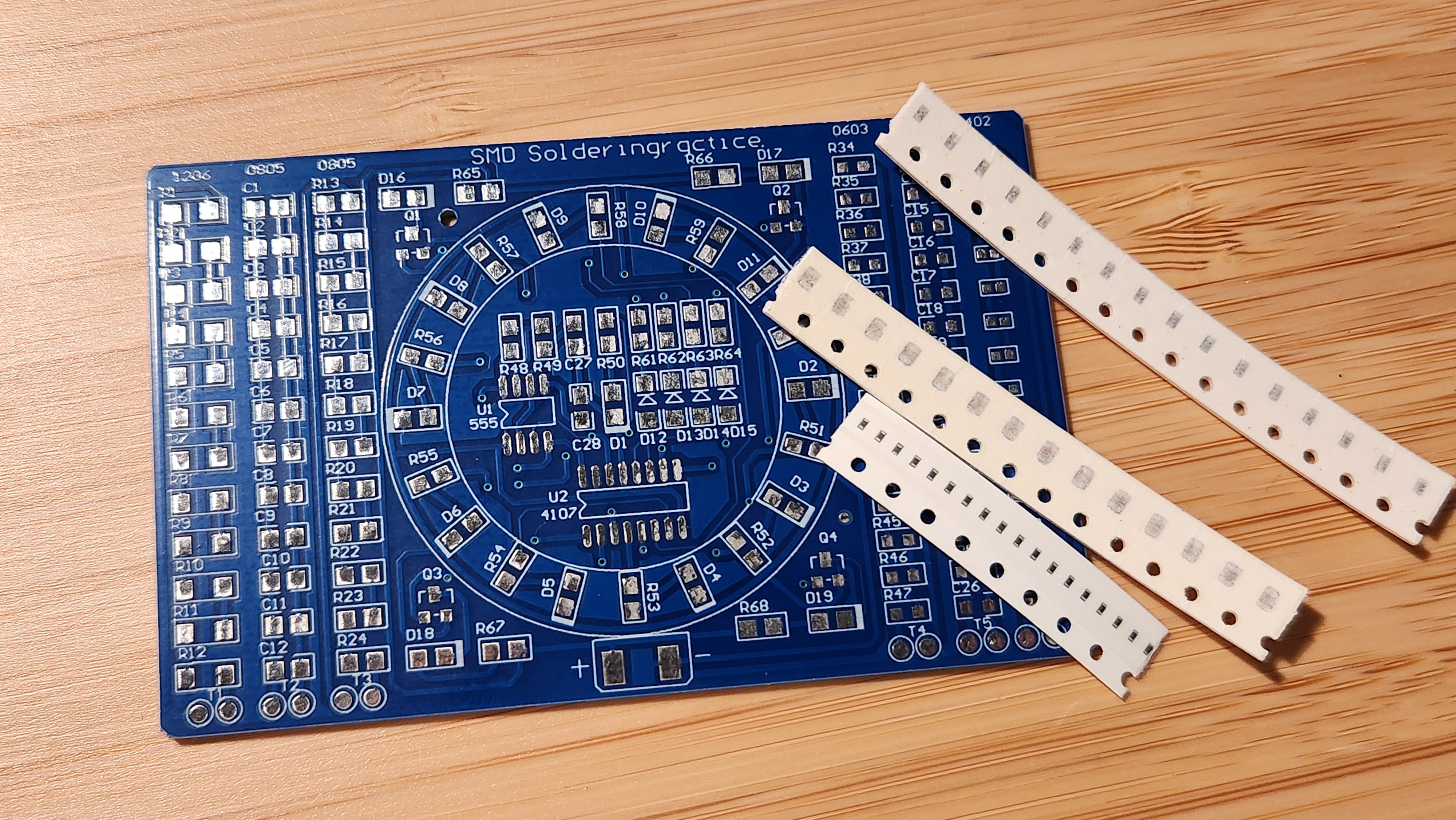
SMD soldering practice kit, £0.75 from AliExpress I also bought an SMD soldering practice kit, if not for learning how to solder SMD components for this project then just for a bit of fun. This consists of a small, and a variety of SMD resistors, capacitors and chips in different sizes to practice with.
I don't think I quite realised just how small SMD components really are - whilst the 1206 and 0805 size look manageable to solder with my iron, the smallest 0402 size ones are absolutely tiny.
Polyphonic Analog Synthesiser
Building a modern interpretation of a polyphonic modular analog synthesizer at the transistor level, inspired by early 1970s-80s designs.

 The relaxation oscillator is one of the most commonly used oscillators for producing square and triangle waves. It takes the form of an op-amp configured as a Schmitt trigger, which is a type of comparator with two voltage thresholds determined by the output voltage, R1 and R2, plus an RC discharge network (R3 and C) which creates a periodic oscillation. The relaxation oscillator is the working principle behind the legendary NE555 timer chip.