Mike Christle
-
New PCB design
2 days ago • 0 commentsToday I finish a new PCB design, Rev3. This time I decided to mount the ultrasonic transmitters and receivers on the PCB. This gives me a 15 by 2 inch board. The plan is to mount the ultrasonics on the back side, then mount the board upside down, with the components hanging down. I was able to take advantage of the extra board space to spread the circuits out. This allowed me to make a two layer board, instead of four, and saved some money.
-
Audio output circuit checkout
06/22/2026 at 16:39 • 0 commentsToday I checked the SN76489 audio generator circuits, and they work great. When I built this on a protoboard it had a lot of ringing. But now that It is plugged into a PCB with a proper ground plane and filter caps, the output looks really clean.
I originally wanted to use the SID chip from the Commodore 64, but they are just to available at a reasonable cost. I also read stories about some of the remade sound chips not working. So I purchased the SN76489 from two sellers on Amazon. Turns out both sent me good chips.
-
Progress on receiver circuits
06/22/2026 at 16:12 • 0 commentsMy apologies for the delay in reporting. Last week my AC died and I had to get a whole new system $$$. Having no AC in Florida in June is not good for my productivity.
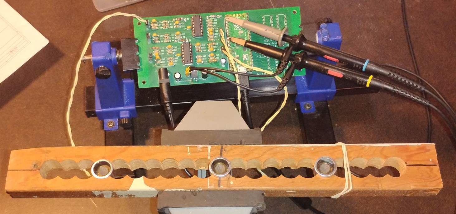
I finally finished up with the receiver circuit. First I experimented with the spacing between transiter and receiver. See picture below. I decided to reduce the distance from 4 inches to 3.5 inches.
Then I found that the output of the receiver circuit was too low in the default state. This meant that the PICO always saw a logic one. I fixed this by adjusting the resistor values so the output defaults to about 0.5V.
![]()
-
Fixed receiver circuit.
06/09/2026 at 14:54 • 0 commentsI changed the driver circuits increase power supply from 12V to 16V, and increased the gain so the output is ~14V.
Increased the gain on the receiver circuit from 100 to 200. Now I am reliably getting pulses at the pico.
I might need to decrease the distance between transmitter and receiver from 4 inches to 3.5 inches. This will take some experimentation.
-
Fixed Driver Circuit
06/05/2026 at 20:00 • 0 commentsFound the problem with the driver circuit. The gain was a little too high. The amp didn't like the signal getting that close to the rail. I dropped the gain about 10% and it works much better.
Now I am looking at the input circuits. I have a first order RC high pass filter to block voices and 60 Hz hum. It appears to be picking up a lot noise and it is having trouble isolating the 40KHz signal reliably. I think I will experiment with a LC filter.
-
Mike Christle
06/01/2026 at 14:54 • 0 commentsThe story so far.
First I bread-boarded the ultrasonic driver and receiver circuits and got them to work reasonably well. However, when I built up the exact same circuit on the PCB it didn’t work for crap. It is either getting way too much gain, or the filtering isn’t working. Next step is to rework the driver circuit using a first order low pass filter.
I also bread-boarded the audio output circuits. Tomorrow I will add these components to the PCB and test.
The Stereo Theremin
With my version each hand controls both pitch and volume. The up/down motion controls volume, and the right/left motion controls pitch.