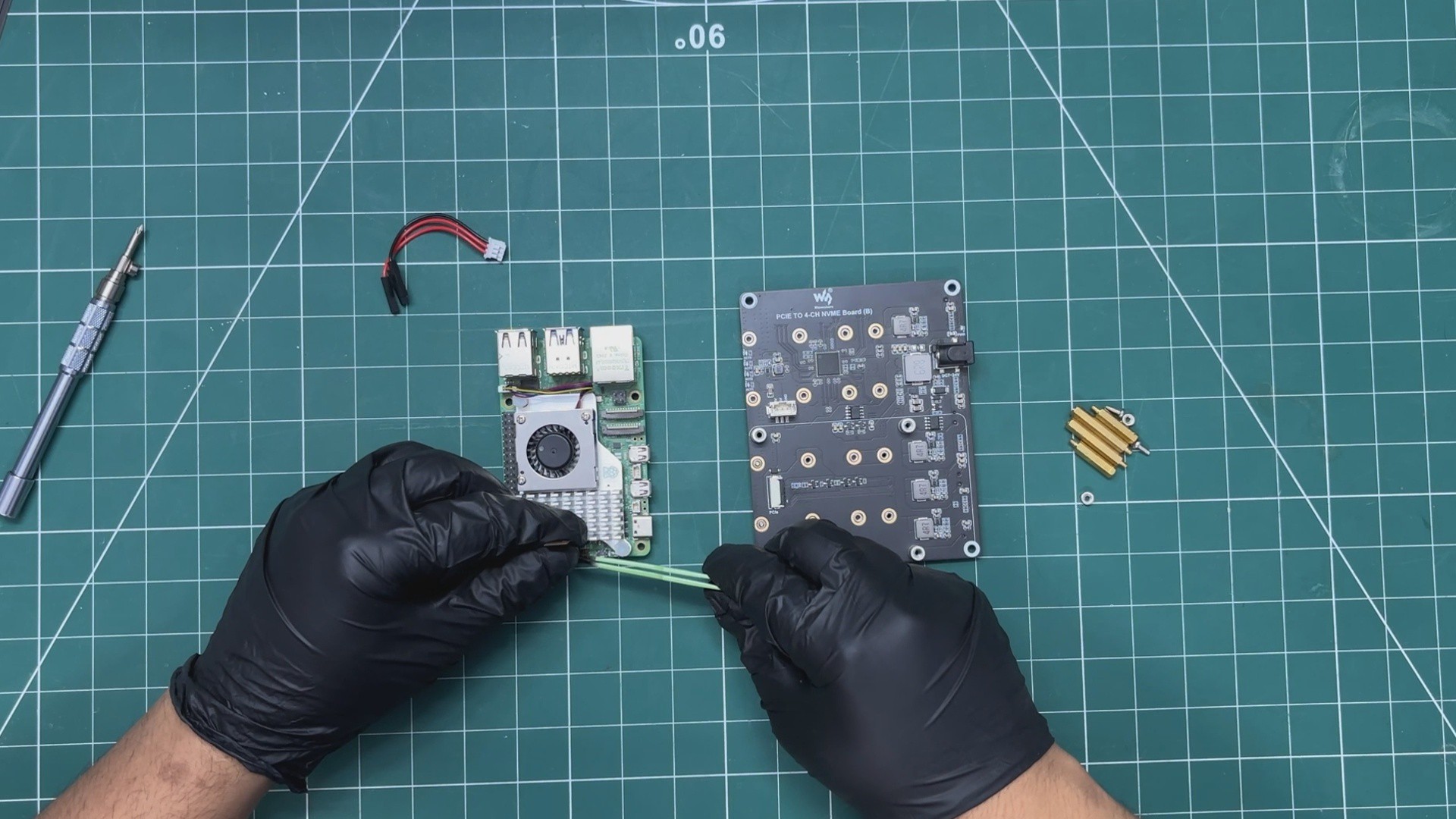
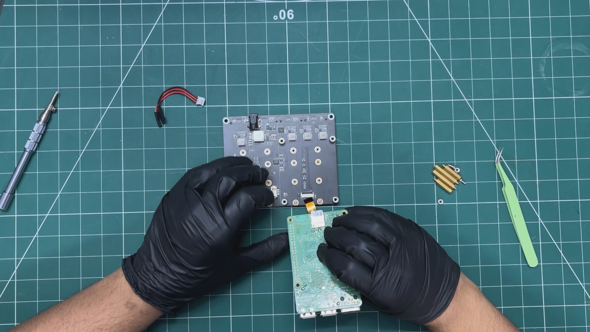
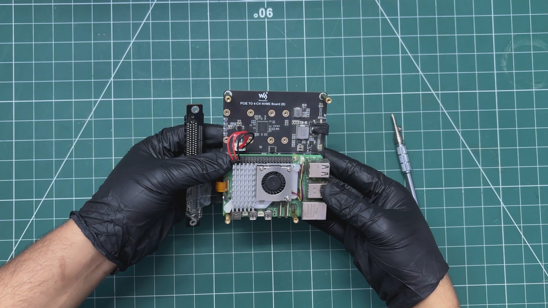
We begin the assembly by connecting the PCIe FFC cable to the PCIe connector on the Raspberry Pi 5. It is important to ensure that the cable is fully seated in the connector, as a loose connection can prevent the setup from working even if the software configuration is correct.
The other end of the FFC cable is then connected to the PCIe connector on the Waveshare four-channel NVMe expansion board.
Next, we mount the Raspberry Pi onto the Waveshare board. We align the mounting holes on both boards and use four M2.5 screws to secure them together.
The CON3 power connector included with the Waveshare board is then connected to the board. The two red wires are connected to the 5V GPIO pins on the Raspberry Pi, while the black wire is connected to one of the ground (GND) pins.
Finally, we install four M2.5 PCB standoffs into the mounting holes on the Waveshare board. In this build, we use 20 mm standoffs to provide the necessary clearance for the rest of the assembly.
2
Pi SETUP with PCIEx16 to NVME ADAPTOR & NVME
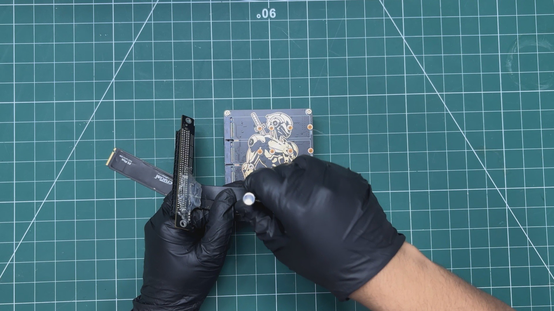
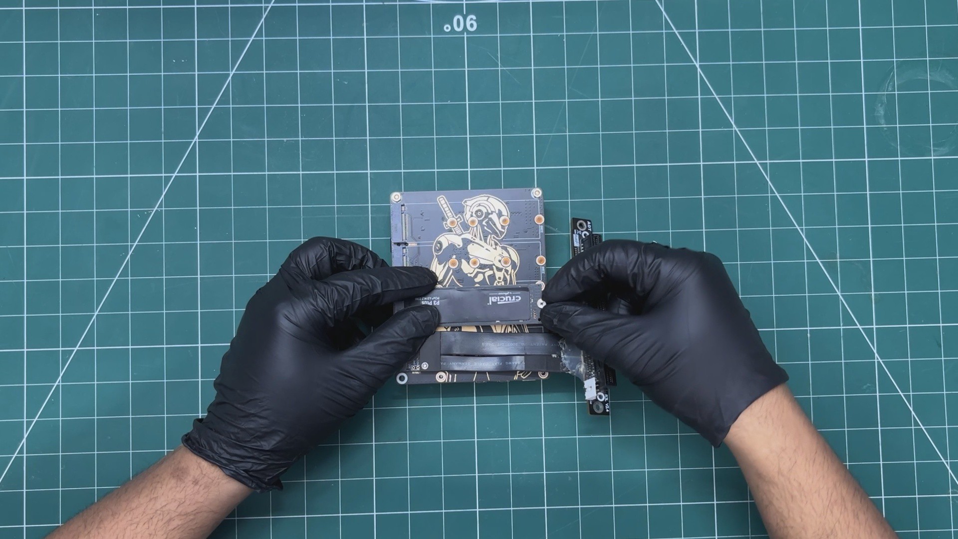
After flipping the Raspberry Pi 5 and Waveshare expansion board assembly over, we connected the ADT-Link M.2 NVMe-to-PCIe x16 adapter to the first M.2 slot on the Waveshare board.
In the second M.2 slot, we installed our Crucial P3 NVMe SSD, which serves as the system drive.
The PCB standoffs that we installed earlier now act as support legs for the entire assembly, keeping the Raspberry Pi and Waveshare board elevated above the surface and preventing the components on the underside from touching the ground.
3
RASPBERRY PI & GPU SETUP
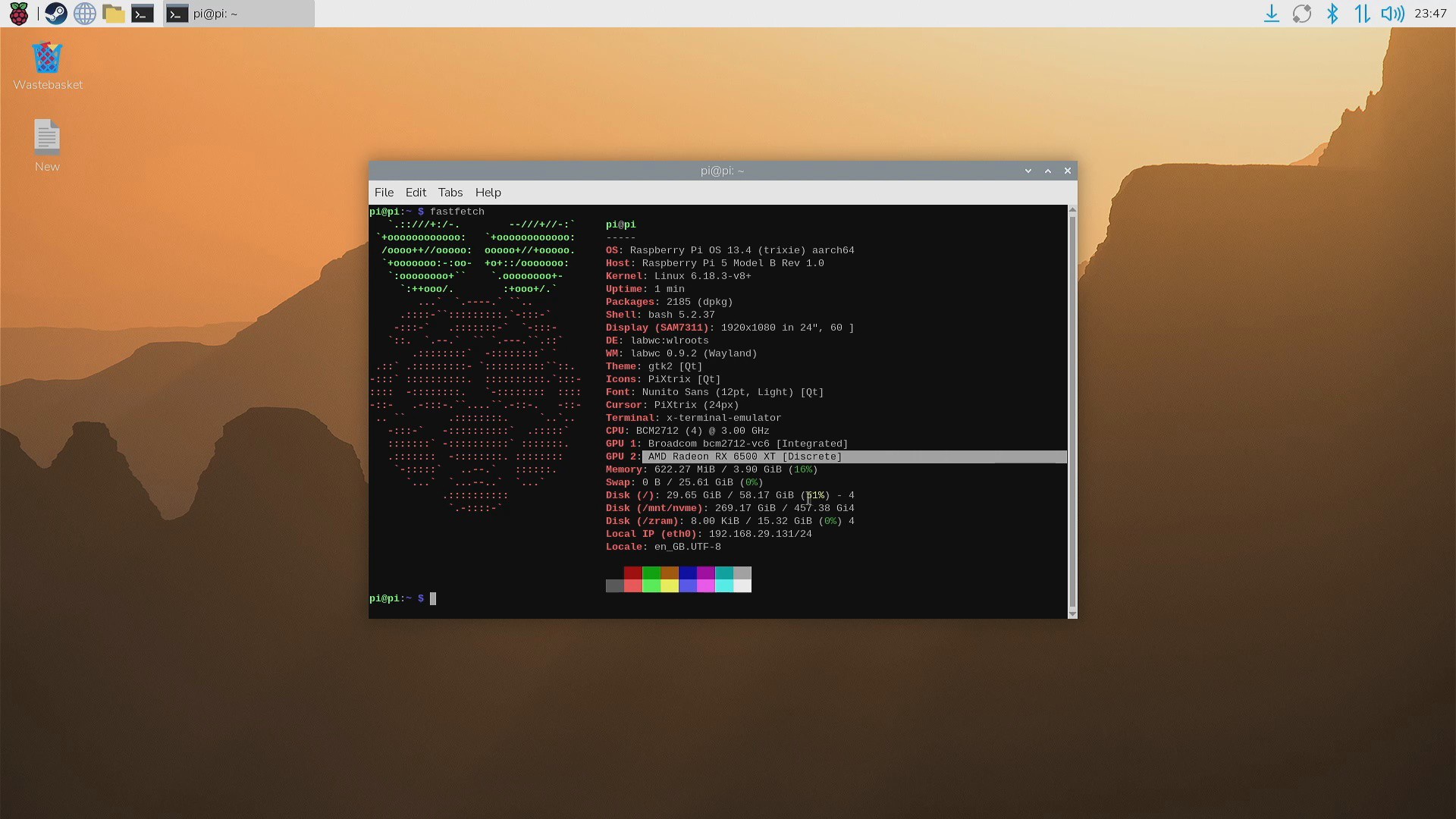
Out of the box, the Raspberry Pi 5 does not provide plug-and-play support for AMD graphics cards. To make the Sapphire Pulse Radeon RX 6500 XT work, I installed the required AMD firmware packages and used rpi-update to flash a custom kernel build that includes the necessary patches and driver support for external GPUs.
Before making any system-level changes, the first step was to ensure that the operating system was fully up to date.
sudo apt updatesudo apt upgrade -y
Next, we installed the AMD firmware packages and then rebooted the system after the installation.
After rebooting, we log back in and install the updated kernel version, which includes the AMD kernel module.
sudo rpi-update pulls/7113
This will update the Linux kernel to the one built off the PR branch. It enables AMD GPU support on both the BCM2711 used in the Pi 4 generation and the BCM2712 for the Pi 5.
Before rebooting, we edited the config file /boot/firmware/config.txt file and added the following at the bottom.
dtparam=pciex1_gen=3 # for faster PCIe Gen 3 speeds on Pi 5auto_initramfs=0 # to avoid 'weird boot mechanisms or file systems'
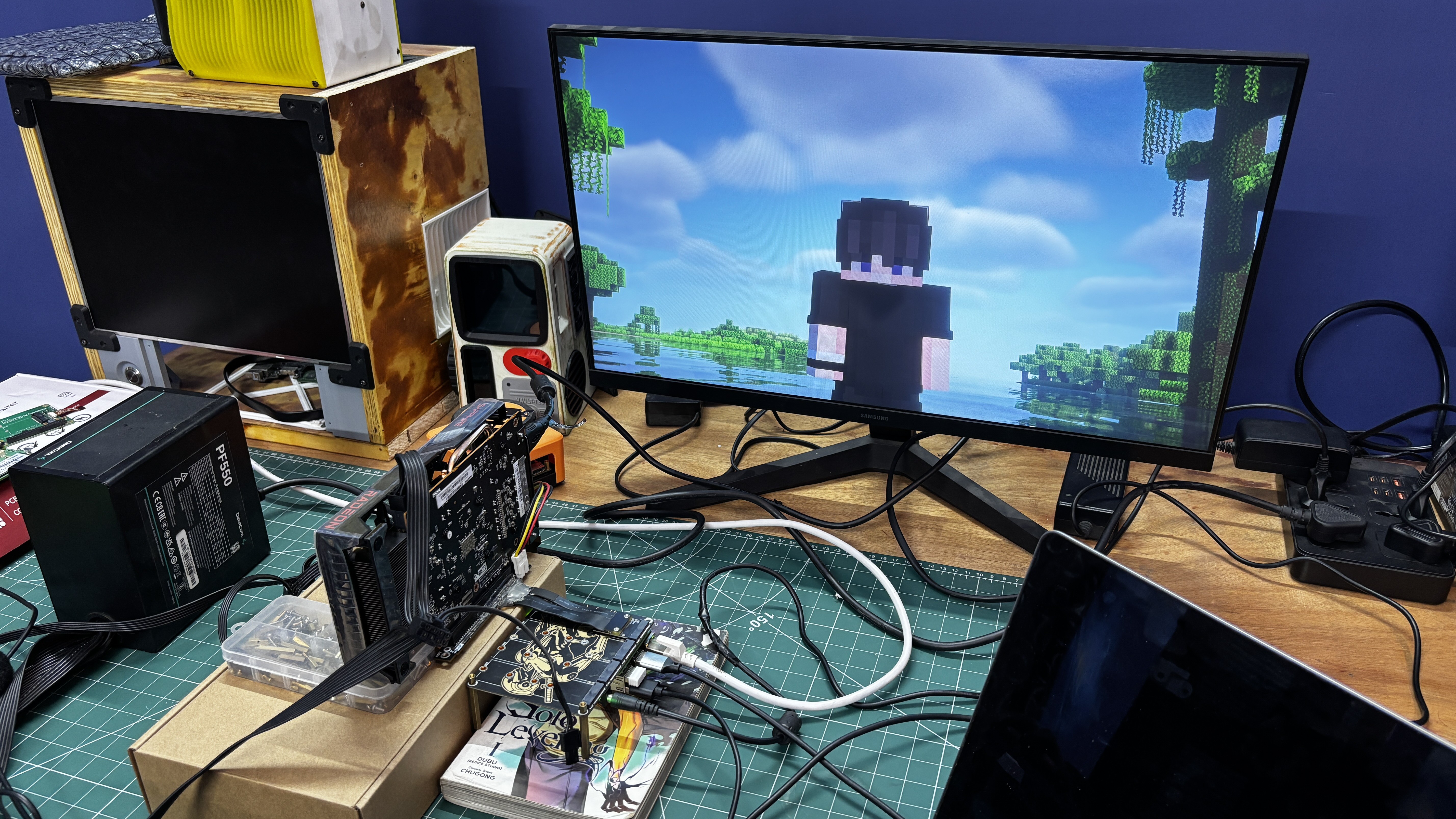
Doing this allowed the Raspberry Pi 5 to work with our AMD Sapphire Pulse Radeon RX 6500 XT. We simply removed the HDMI cable from the Raspberry Pi’s onboard HDMI port and connected the monitor directly to the GPU, after which the setup started working.
To verify that everything was functioning correctly, we installed Minecraft: Java Edition and ran it with BSL Shaders. The performance was incredibly smooth and did not feel like we were playing on a Raspberry Pi.
Minecraft can run on the Pi without a dedicated GPU, but shader packs are generally too demanding for the onboard graphics. With our external GPU setup, however, the game ran smoothly even with BSL Shaders enabled.
4
POTATO PC 3D MODEL
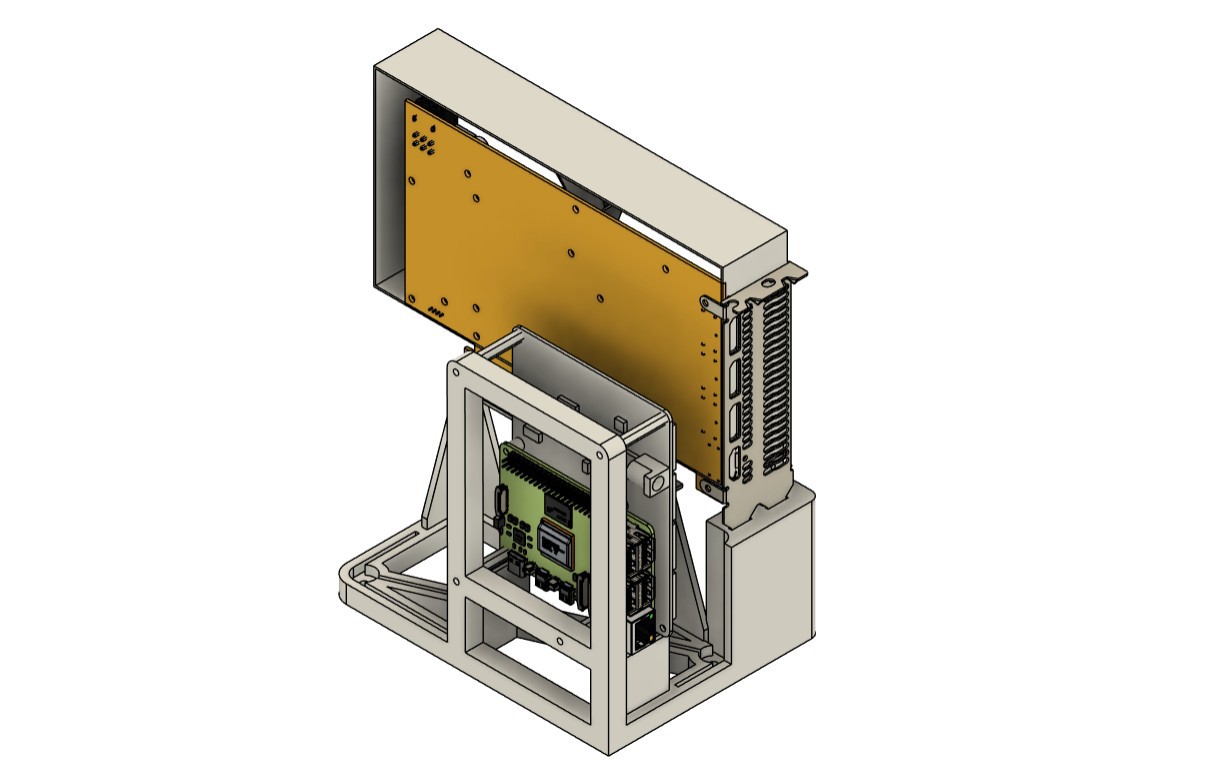
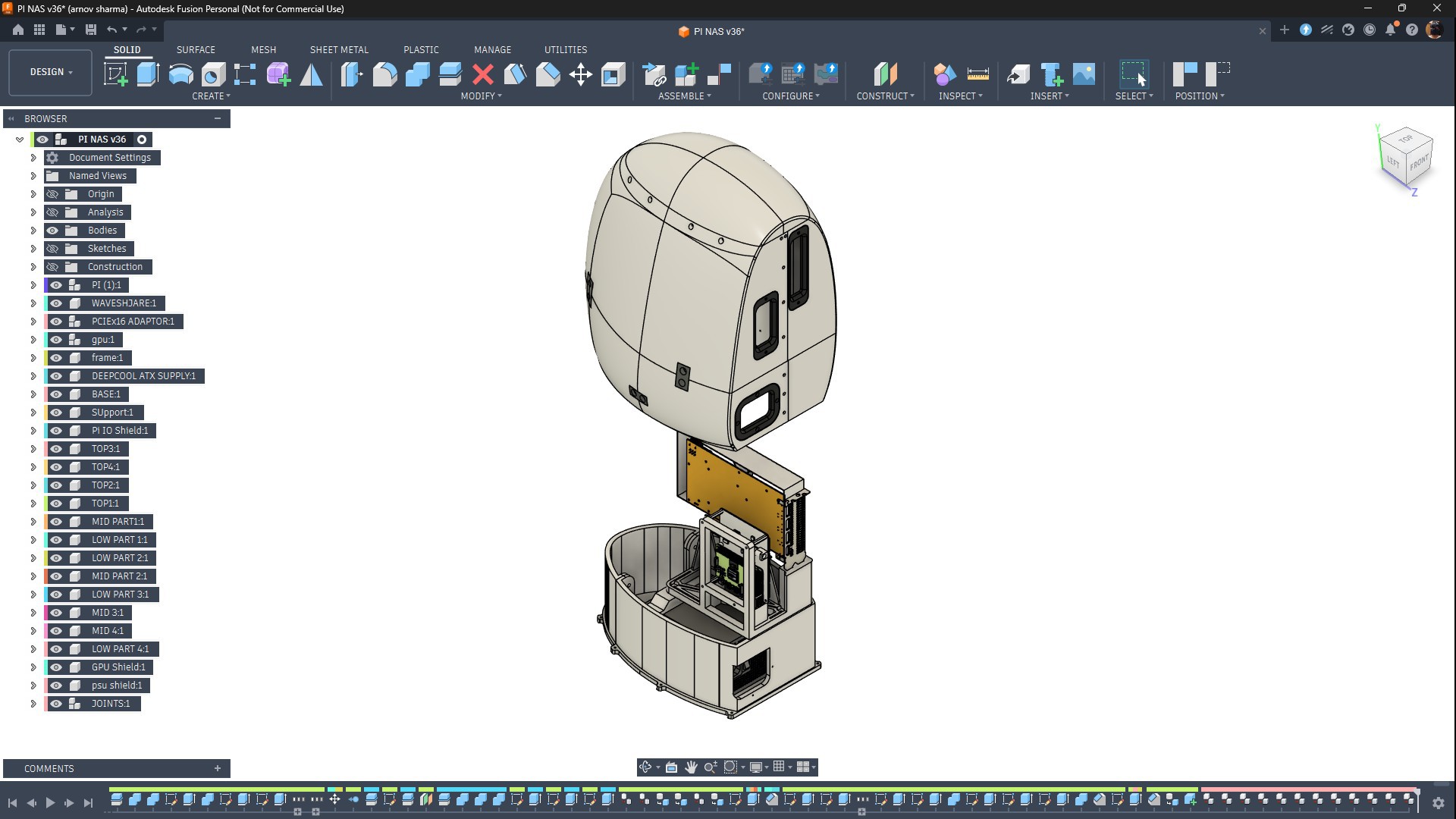
For the 3D design of our Potato PC, we began by importing the CAD models of all the electronic components used in the build. This included the Raspberry Pi 5 and NVMe expansion board assembly, the Sapphire Pulse Radeon RX 6500 XT, the PCIe adapter, and the power supply.
We first arranged all of these models in their desired positions and then designed a minimal frame to hold the Raspberry Pi and NVMe board assembly, along with the graphics card and PCIe adapter.
This frame assembly served as the central structural component of the design. We positioned it above the power supply and created a base that securely holds the PSU while also supporting the frame assembly.
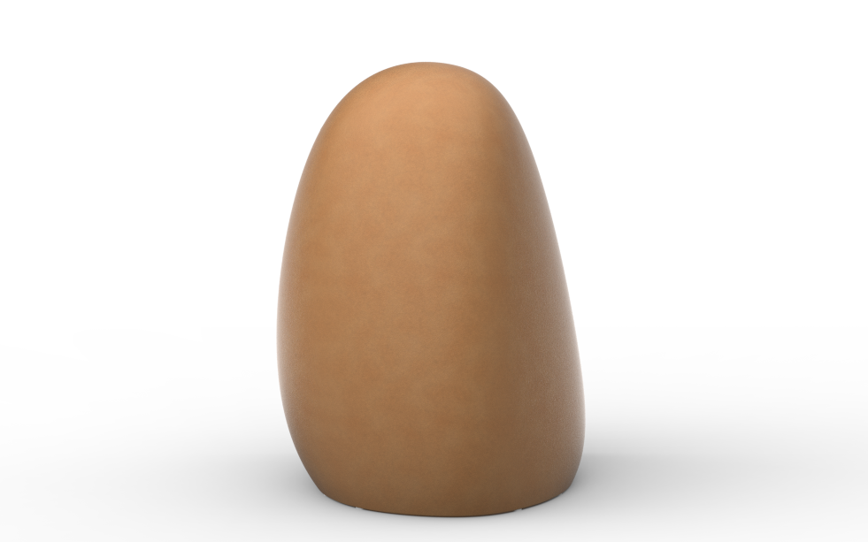
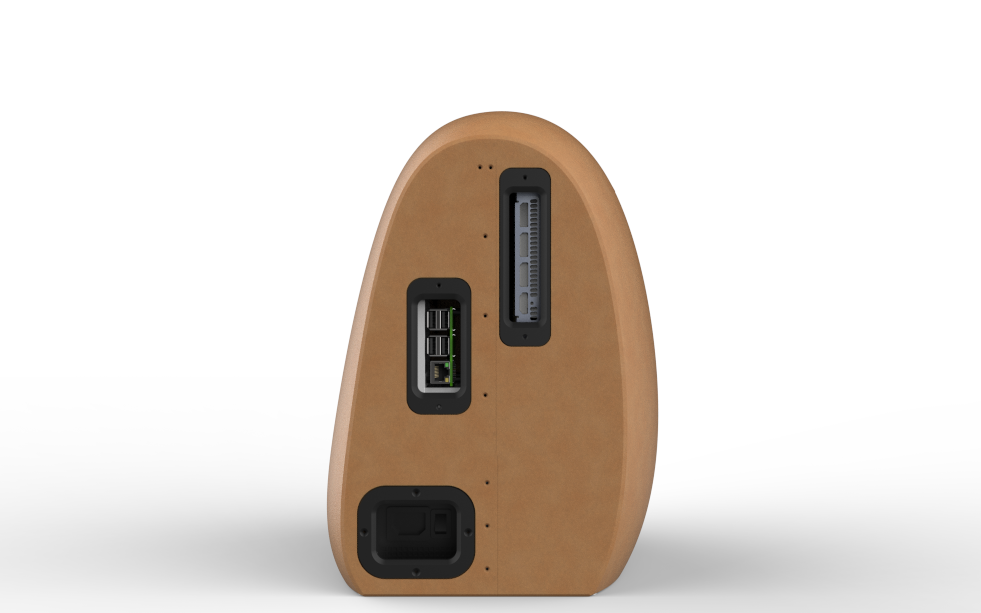
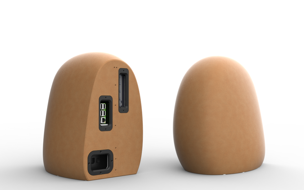
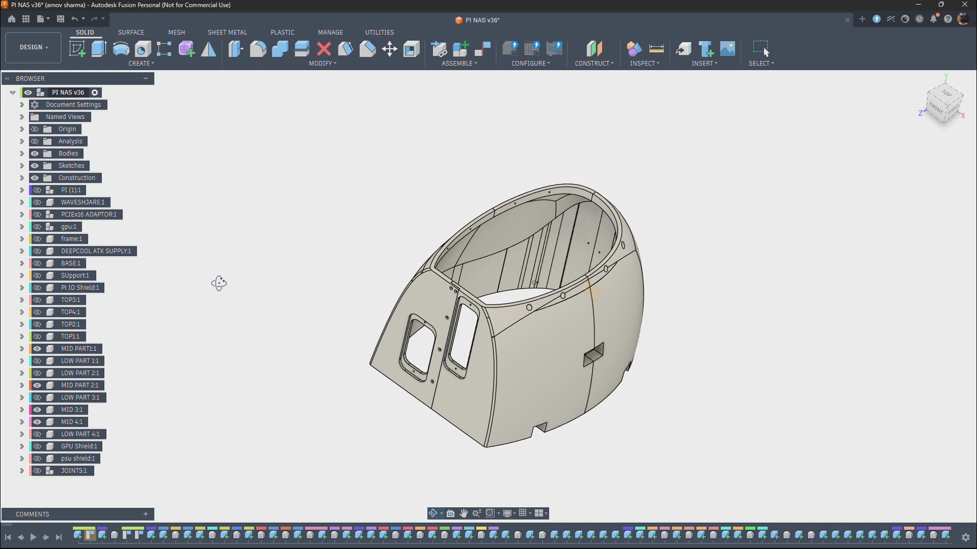
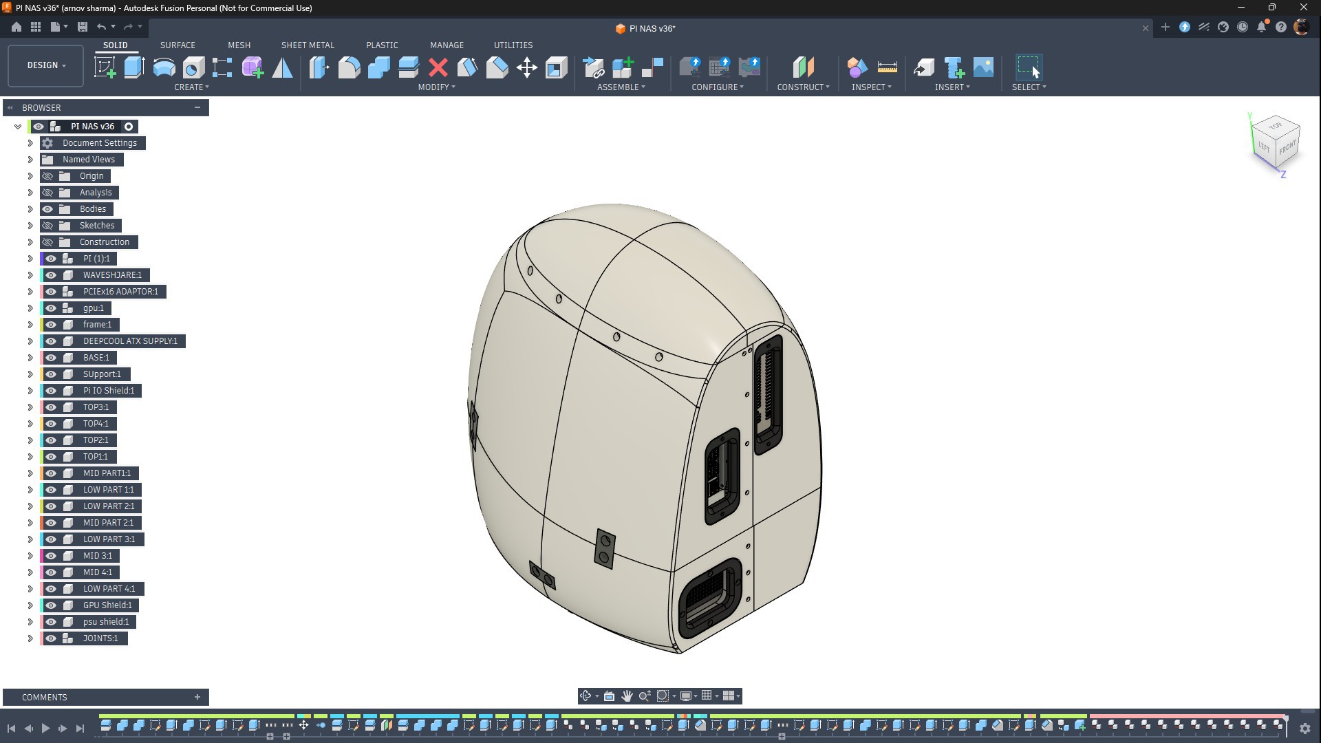
Finally, we modeled a potato-shaped enclosure around the base using the surface modeling tools in Autodesk Fusion. Our goal was to create an asymmetrical outer shell that closely resembles a real potato.
5
POTATO ENCLOSURE
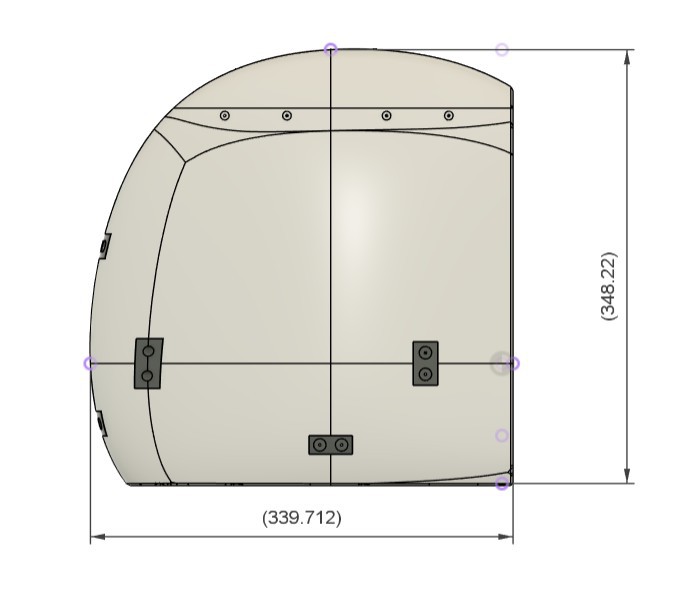
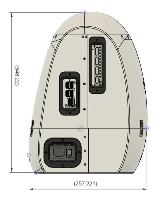
The enclosure itself was quite easy to model, but there was one major challenge: its overall dimensions are 350 mm × 257 mm × 340 mm.
The 3D printer I'm using has a build volume of only 255 mm × 255 mm × 255 mm, which meant the enclosure was too large to print as a single piece.
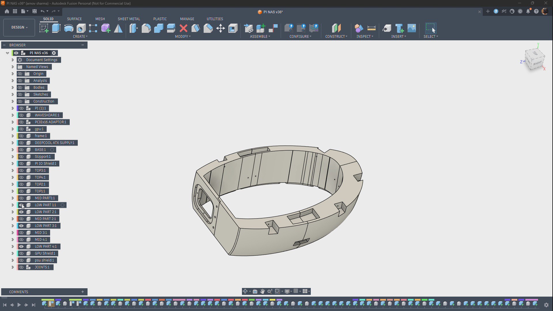
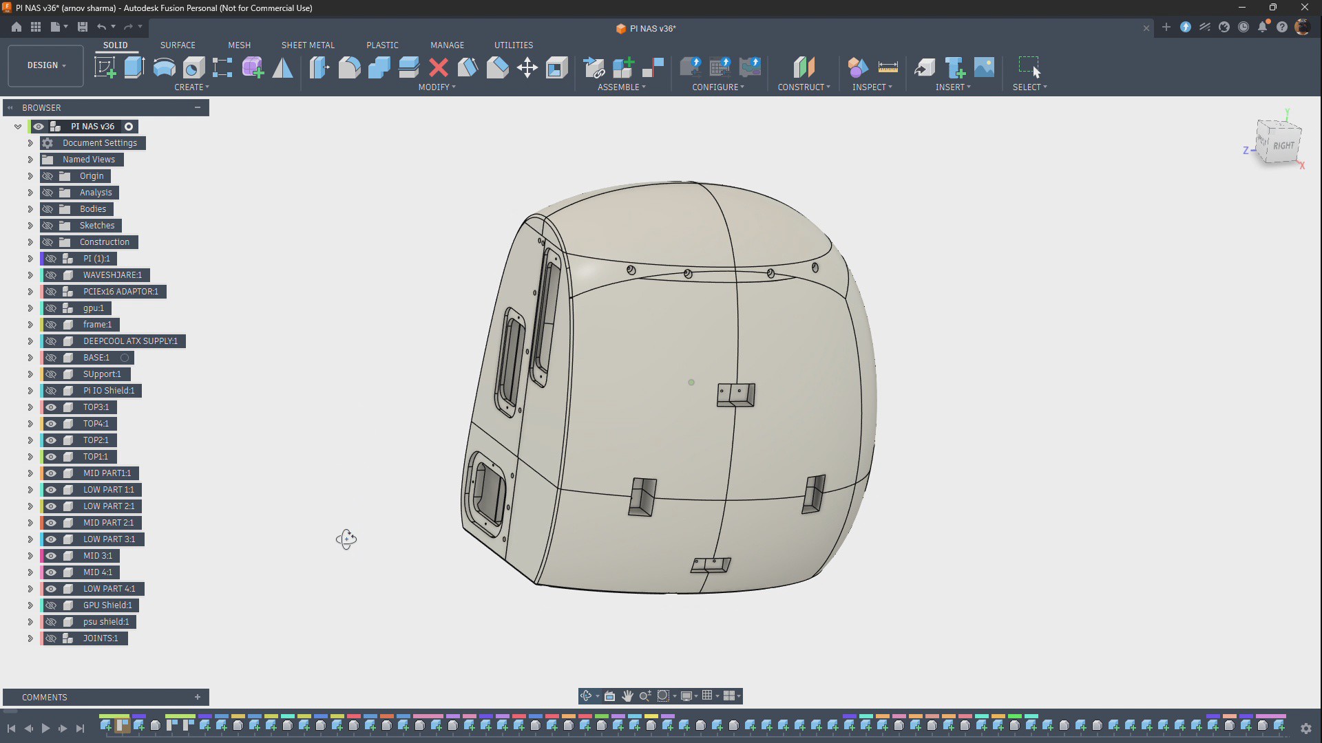
To solve this, we divided the enclosure into multiple parts, printed each part separately, and then assembled them to create a single enclosure body.
6
JOINTS
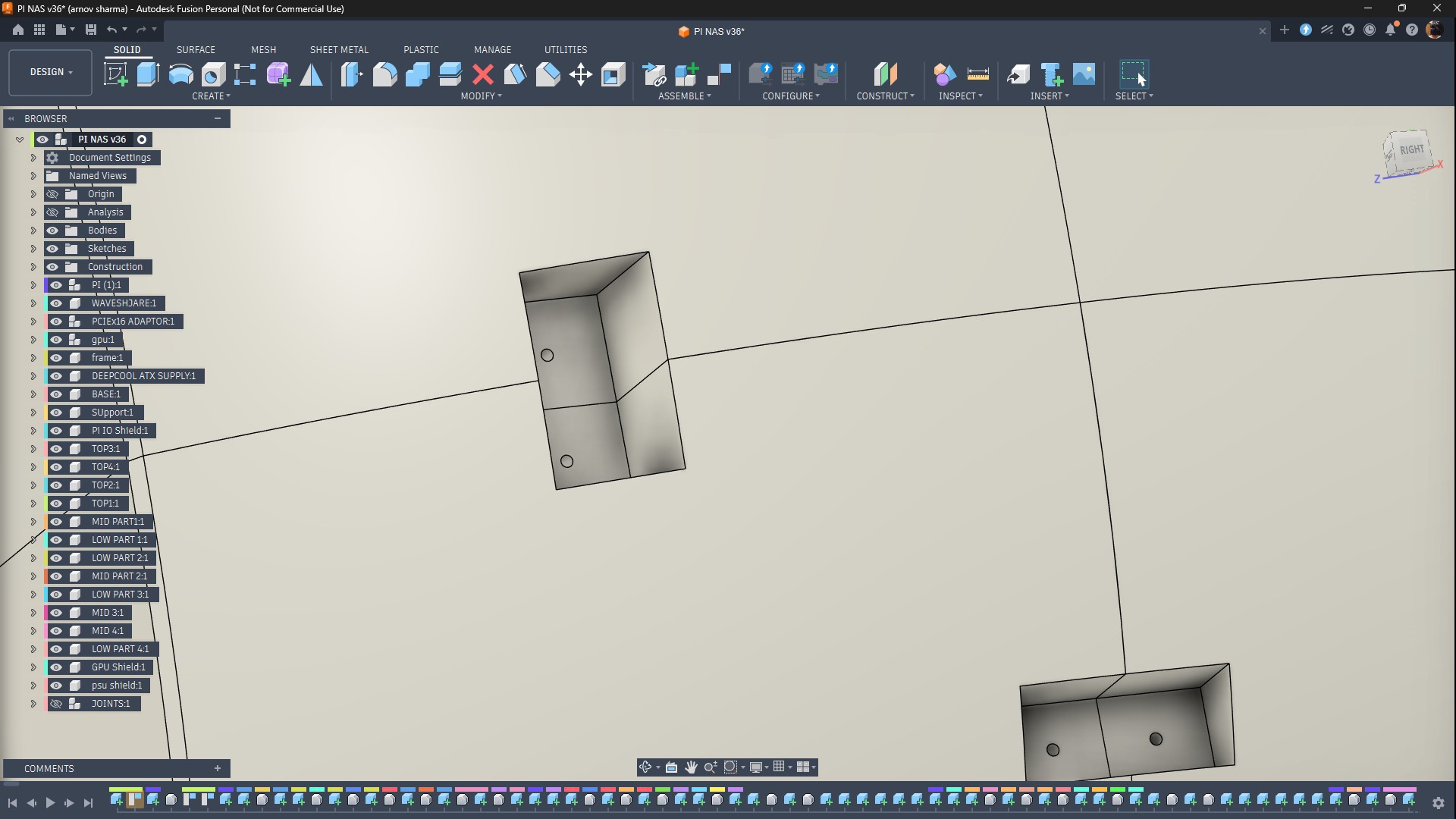
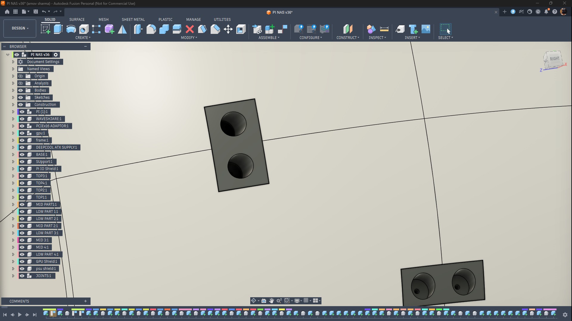
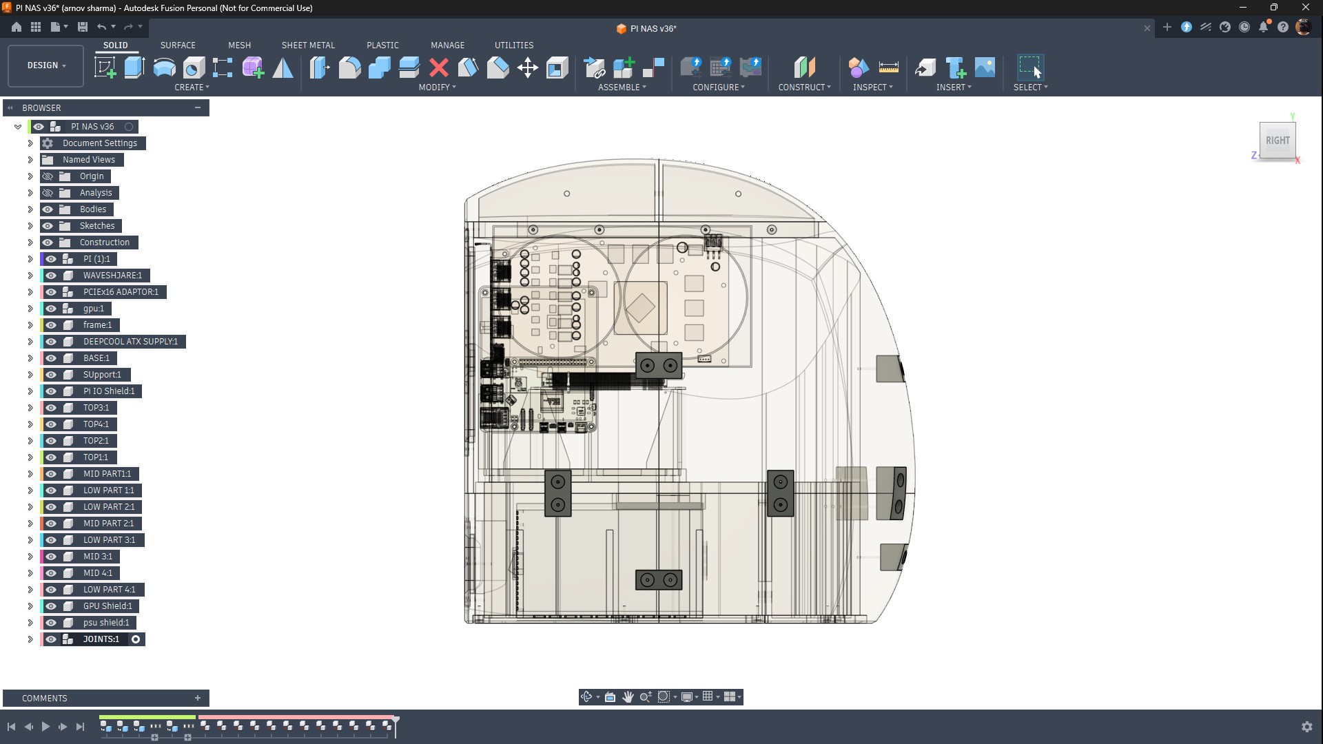
To join the enclosure parts together, we added several rectangular slots along the dividing lines between adjacent parts. A rectangular joint fits into these slots and connects the two pieces together.
This joining method was inspired by woodworking, where two parts are connected by cutting matching slots and inserting a third piece between them.
To secure each joint to the two enclosure halves, the joint includes two screw holes. We use M3 screws to fasten all three parts together.
All of the enclosure parts are connected using this same joint design.
7
FRAME ASSEMBLY
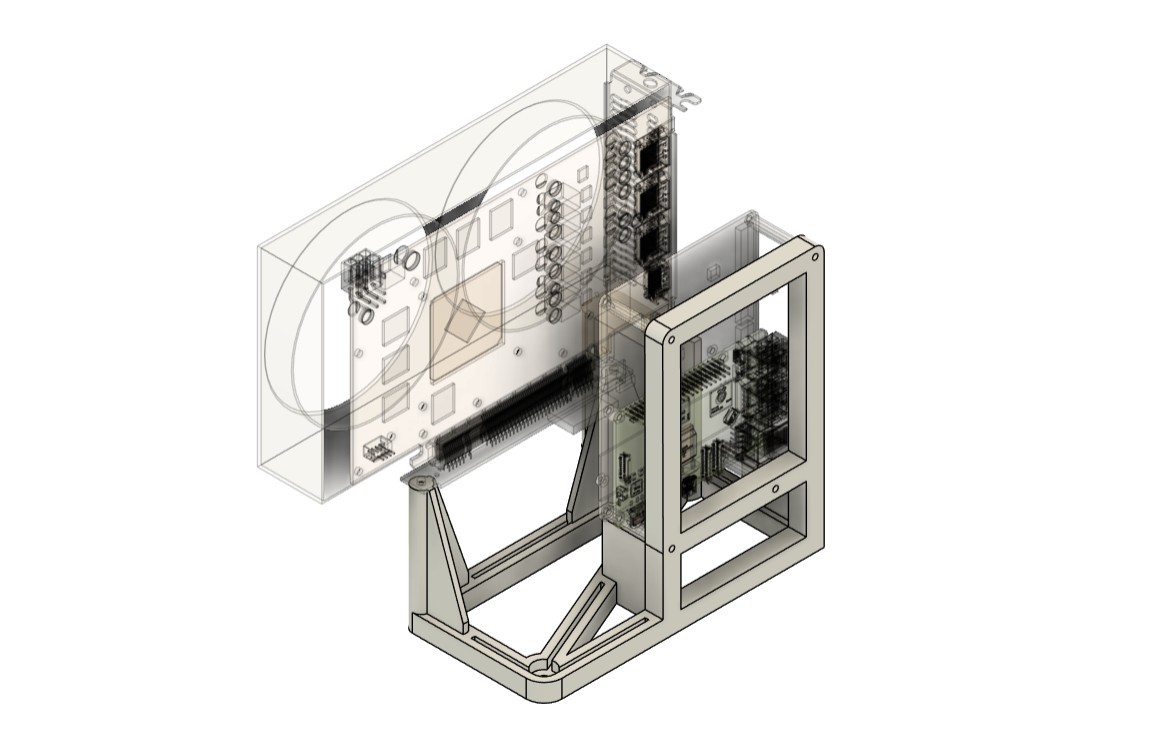
I modeled a custom frame that holds the Raspberry Pi 5, GPU, Waveshare expansion board, and PCIe adapter all together as a single assembly.
This frame serves as the primary structural component of the project. It keeps the Raspberry Pi and GPU securely mounted together, making it essential for both the initial testing phase and the final assembly of the Potato PC.
8
BASE
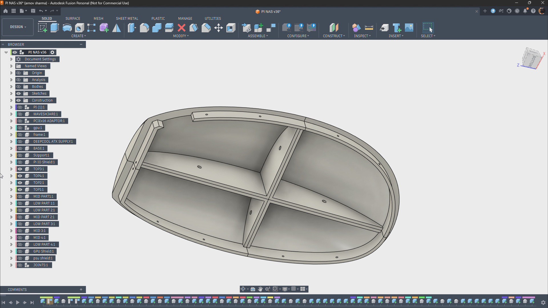
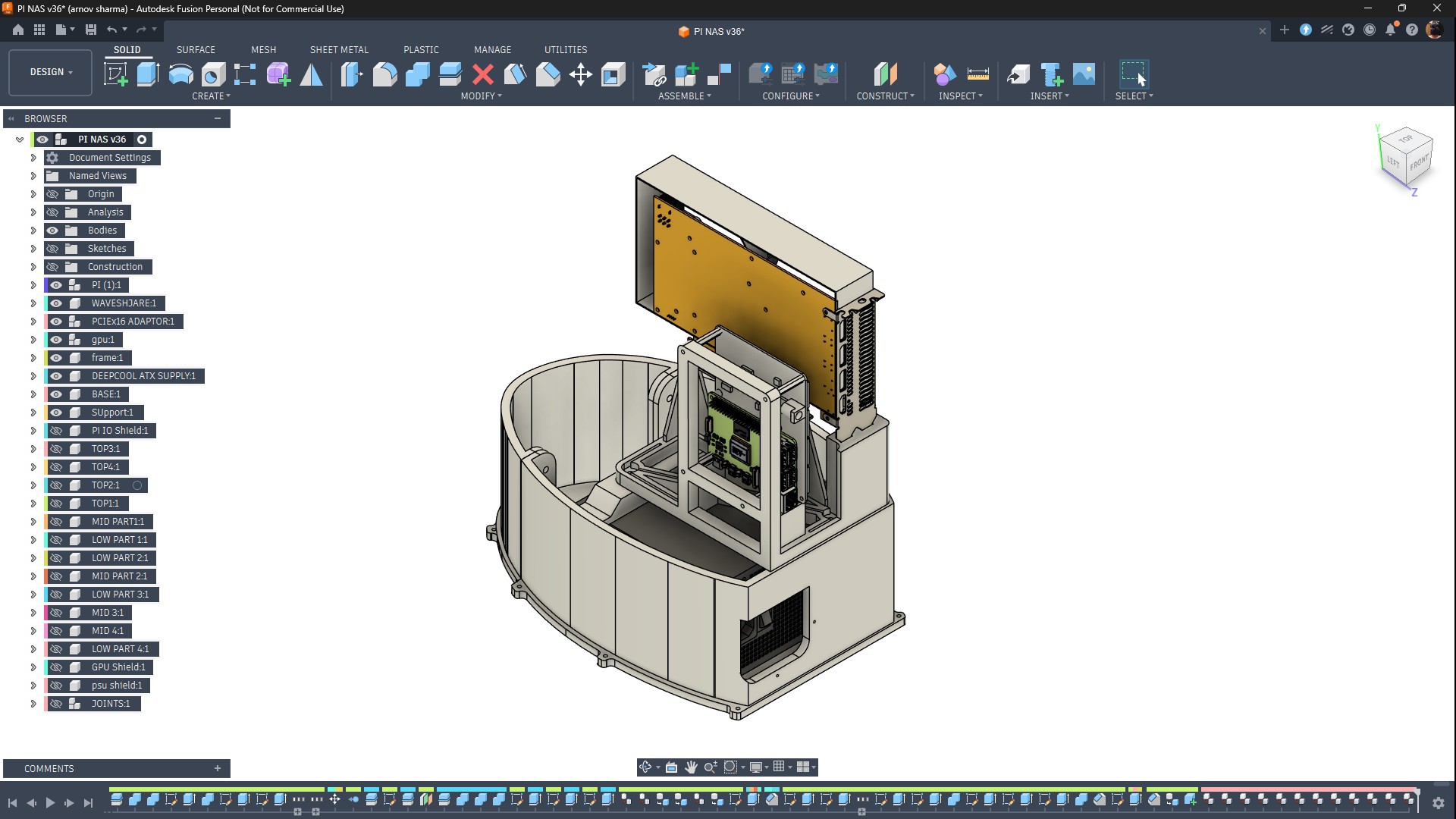
The base is designed so that the potato enclosure can slide over it and fit securely into place.
To accommodate the build volume of our 3D printer, the base was divided into two separate parts. Both parts were printed individually and then joined together to create a single base unit.
The frame assembly is mounted onto the base, and the entire structure is enclosed by the potato-shaped shell.
To lock everything in place, screw holes are added to the bottom side of the base. M2 screws are inserted from the bottom to secure both the enclosure and the base together, forming a single rigid assembly.
9
3D PARTS- POTATO ENCLOSURE
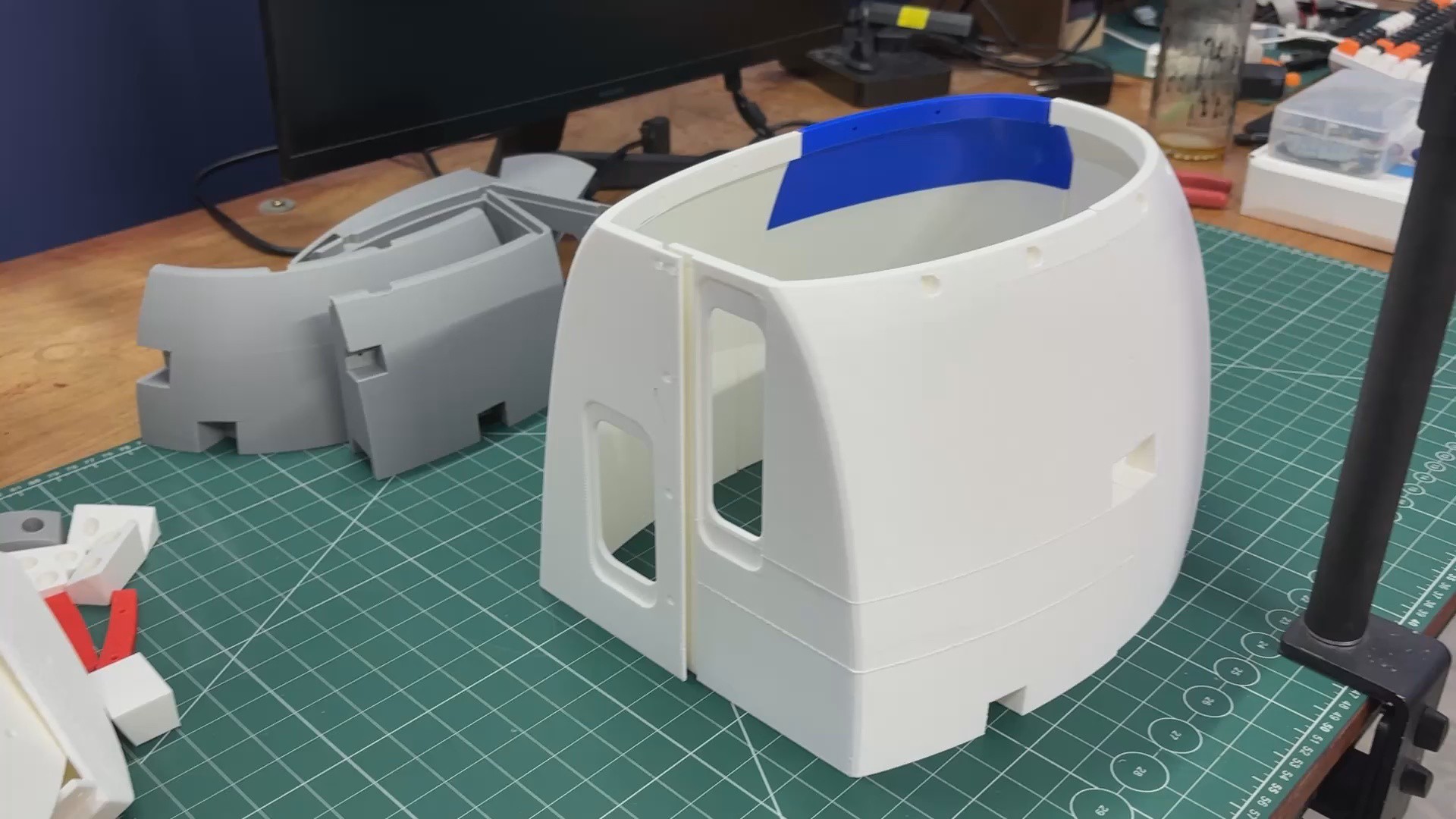
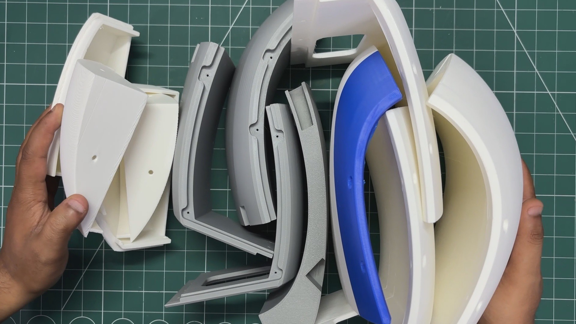
For the Potato PC enclosure, I printed a total of 12 parts. The model is divided into three sections: the top section contains four parts, the middle section contains four parts, and the bottom section also contains four parts.
My goal was to assemble these parts like LEGO pieces to create a single PC enclosure. Since my 3D printer has a build volume of 255 × 255 × 255 mm, which is smaller than the overall size of the enclosure, I had to divide the model into multiple parts before printing.
For each part, I used Creality Hyper PLA with a 0.28 mm layer height. For infill, I used 10% gyroid infill for extra strength. Each part took roughly 4 to 5 hours to print.
Some parts were printed in colors other than white for two reasons. First, I ran out of white filament—this project used around seven rolls of PLA. Second, I planned to do a full surface-finishing process on the enclosure, so the original filament color didn’t matter whether the parts were printed in red, blue, black, or any other color.
10
Pi FRAME ASSEMBLY
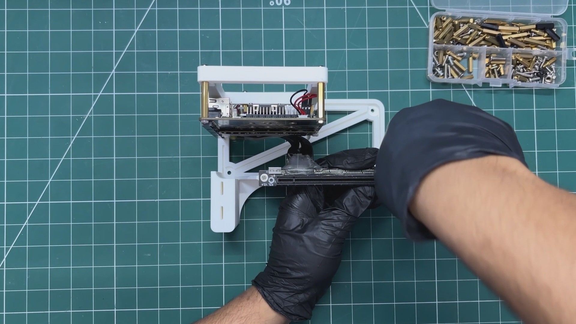
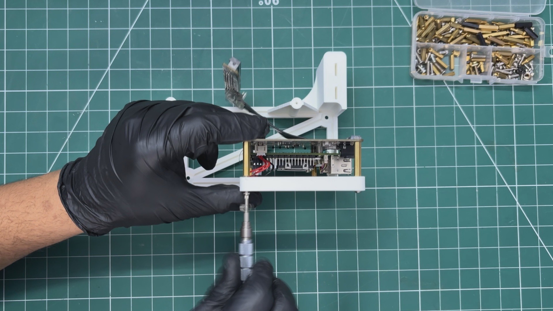
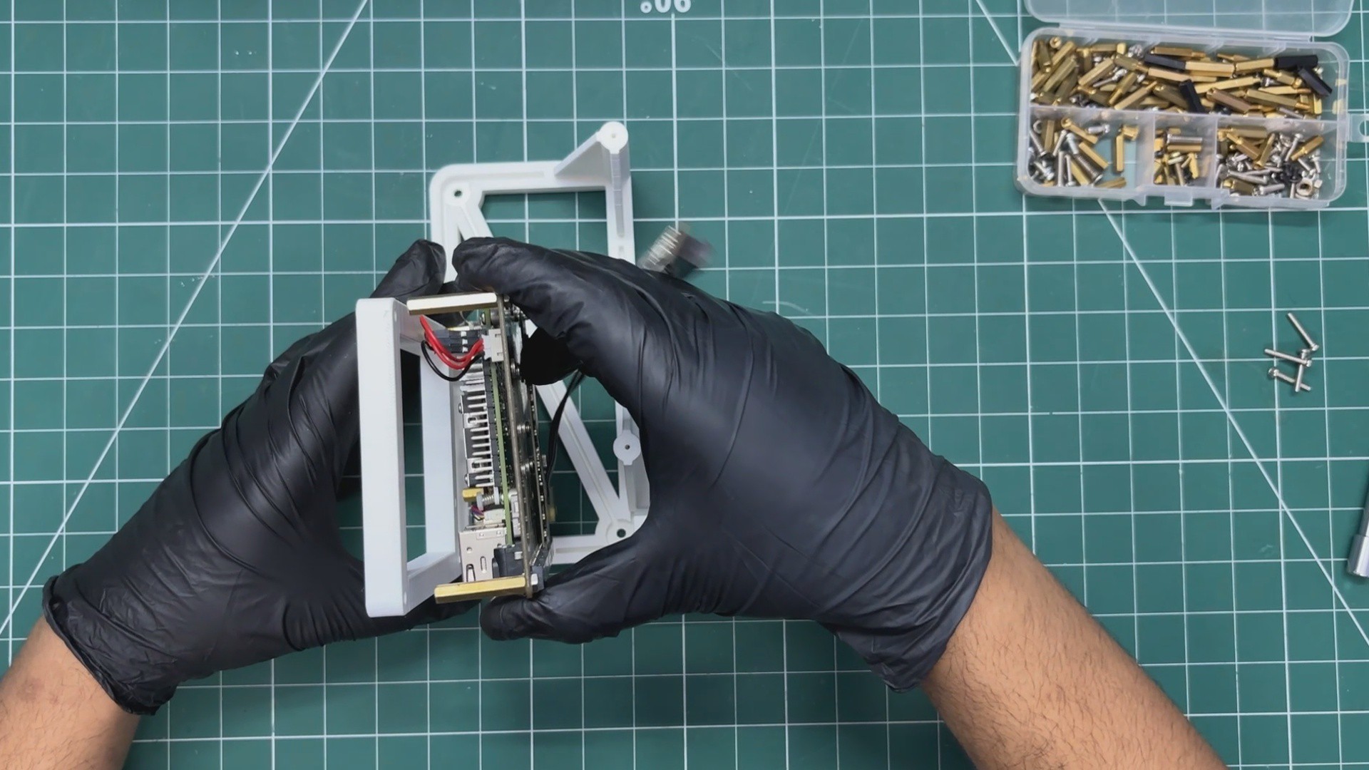
The Pi frame assembly begins by placing the Raspberry Pi 5 and Waveshare board setup onto its mounting position on the frame. We align the PCB standoff holes with the mounting holes on the frame, then use four M2.5 bolts to secure the assembly in place.
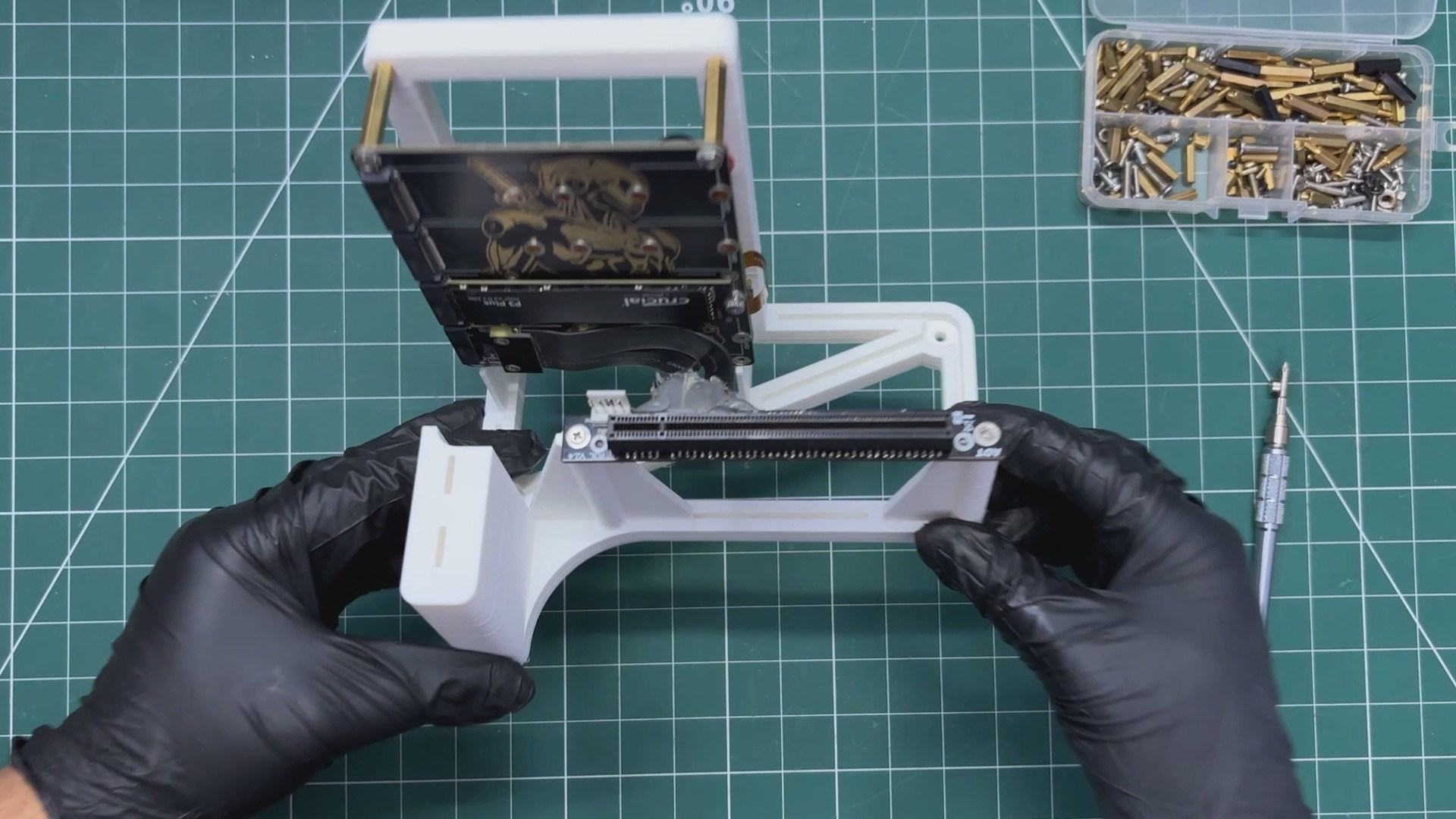
Next, we position the PCIe x16 to M.2 adapter in its designated location. We align it with the mounting holes and use two M2 screws to fasten it securely.
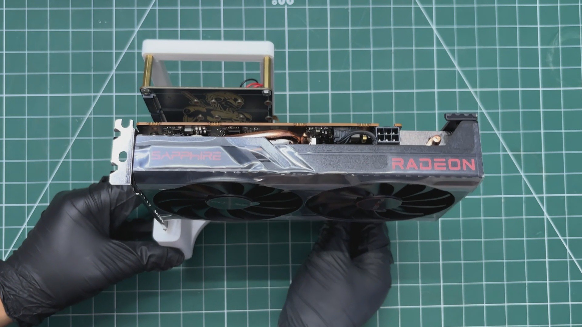
Finally, we place the GPU into position, insert it into the PCIe x16 slot, and secure it in place, completing the setup.
 Arnov Sharma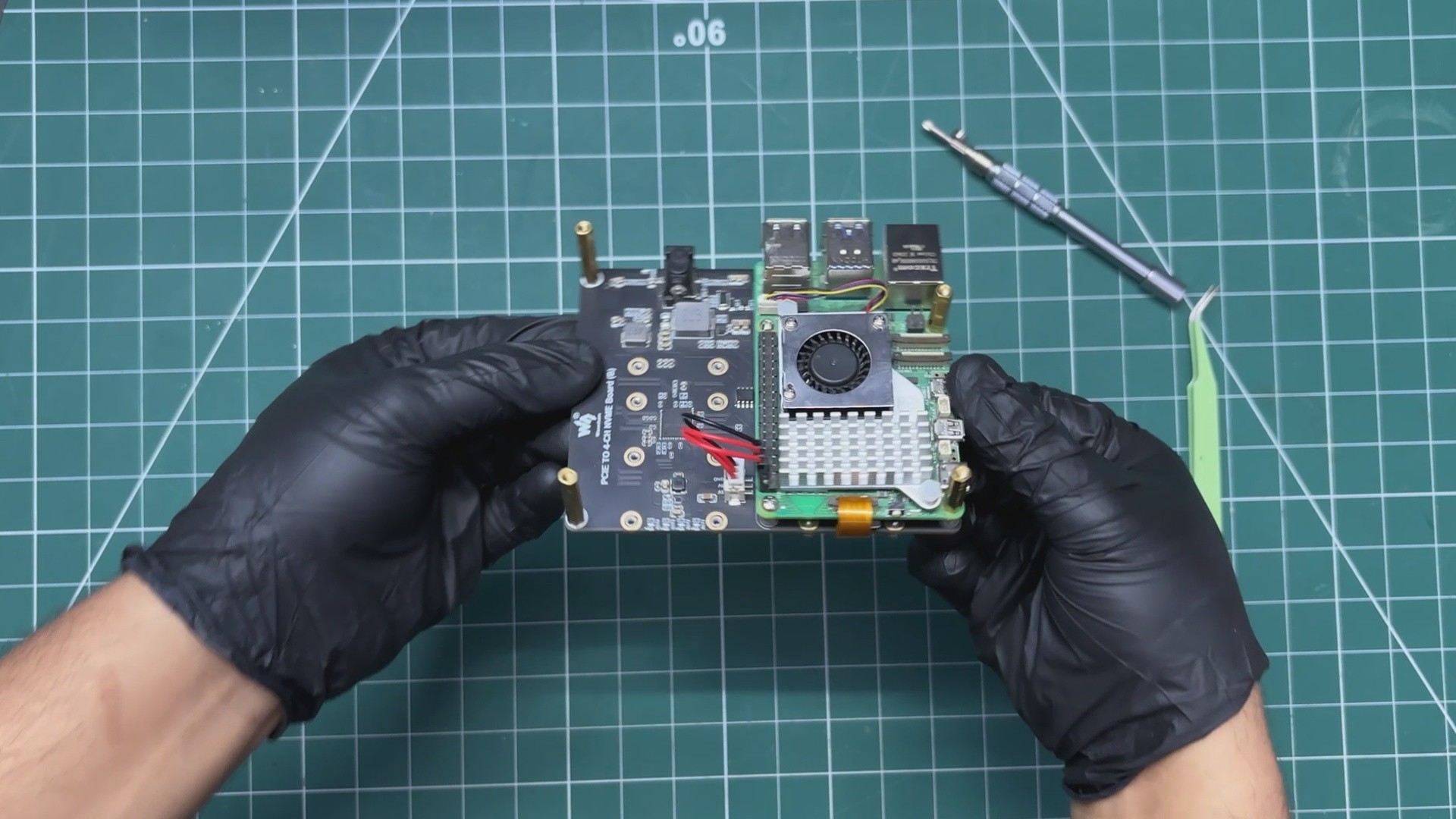
Discussions
Become a Hackaday.io Member
Create an account to leave a comment. Already have an account? Log In.