 Yann Guidon / YGDES
-
Power on reset and external pull-downs
14 minutes ago • 0 commentsSo now, RESET is not a level-triggered signal but a sequence.
The previous scheme was to implement weak pull-ups on SC and SD to force it by default. Convenient, simple and no fuss.
But the last log Direct read / flow-through adds a new wrinkle.
The DTAP has several constraints, such as
- It is independent from system reset or system clock, the DTAP may not rely on their presence to initialise.
- All latched values in the chain are unknown and considered random at power up. There is no known/safe way to have a register powering up to a given value (except with the reset input).
- The whole circuit must be able to work when the DTAP is not connected or in use. The system under test must be autonomous and may not rely on the presence of a DTAP controller to initialise.
A pair of weak pull-ups is still "safe" but its actual effect is unknown. Except that in all cases, if you take most cells in the chain, their values will be the same. Which is a condition that can be easily tested.
-
Direct read / flow-through
5 hours ago • 0 commentsIn our series "yet more things that usual scanchains and even JTAG can't do", here comes...
.
.
There are 4 sequences that produce overlapping pulses, and one of them is chosen for RESET.
An overlapping sequence makes the whole shift register "transparent", which is useful for the RESET cycle, but can also serve other purposes.
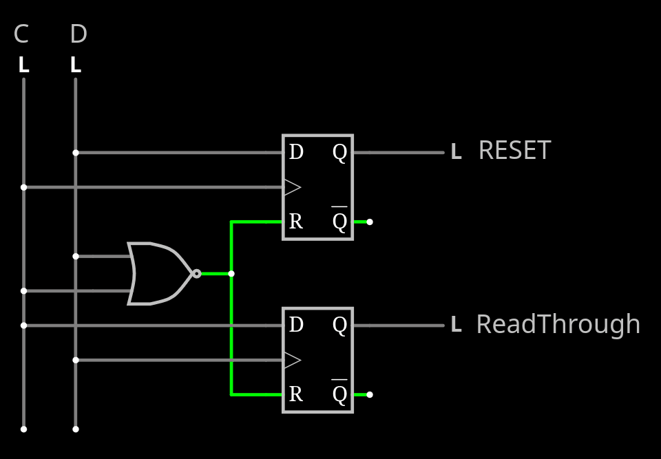
RESET is defined as SD+ SC+ SD- SC-
Now, what if there was a sequence SC+ SD+ SC- SD- ?
- Capture would not be affected because SD=1 resets the counter.
- The Update counter is reset too
- But the Update signal is active when SD=SC=1.
Apart from the last point, nothing changes, the chain is flow-through.
Now what if we could tell the overlap is a reset command or not ?
In the chain, a given set of cells can act as MUX such that a given signal is not only captured, but directly read (through the rest of the chain) and observed in real time, for onchip debugging.
Inserting a MUX in the scan chain is easy, the control though is not. There needs to be a "update" cell (3 latches) controlled by the update counter, which can itself be reset. So there must be an extra state bit that tells if an overlapping sequence is a reset or flow-through.
Two bits of "update" can select among 3 sources, and default to normal chain upon reset. So there's now a MUX4 with 3 state bits.
.
.
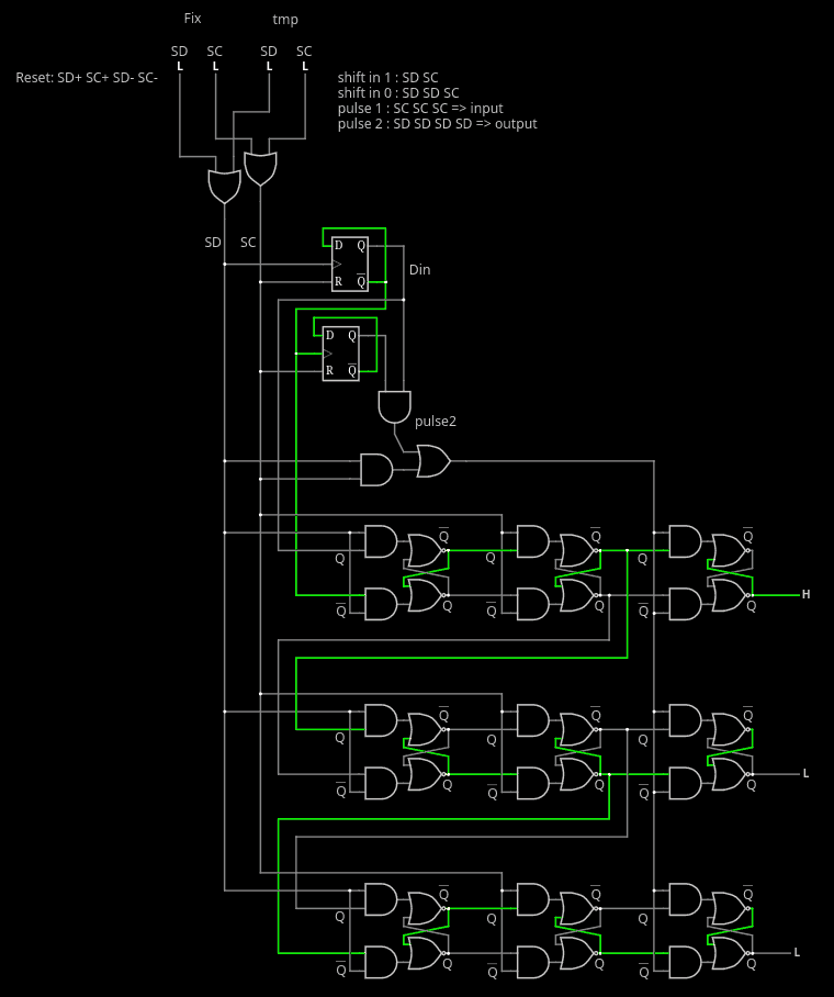
Decoding a RESET and a read-through is a circuit called "phase discriminator", I think, it's common in position encoders (mouse wheels etc). It's quite simple to do, one gate and two DFF.
![]()
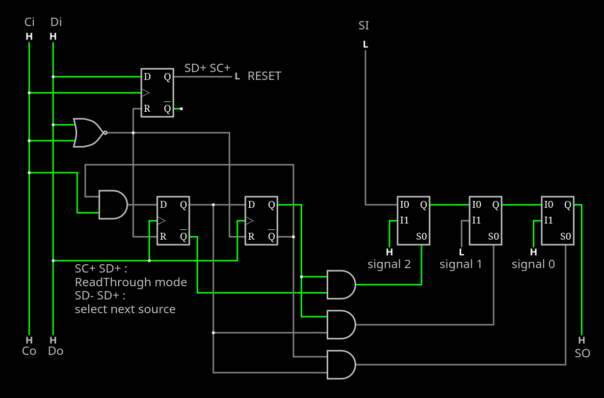
One can easily notice that the sequence at the start matters, but then it can end in any of two ways without difference. This could be used to send more pulses, to select a different signal source.
In the following circuit, a Johnson counter selects one out of three sources to insert in the chain.
![]()
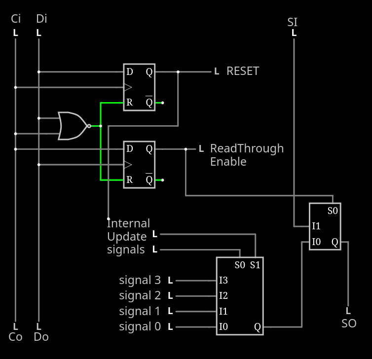
But the control logic becomes more elaborate, as the number of signals to observe increases, so the following circuit may look easier to implement:
![]()
wooops swap the MUX2 polarity...
.
Of course : the observed signal will be delayed "quite a bit" proportionally to the distance from the output pin so these stages should be at, or near, the end. But there is no strict requirement and it's application dependent so if the signal is slow, well, you don't need to bother. It's flexible !
Anyway, can your JTAG system be used to select one signal for real time observation ?
-
Alternating polarities
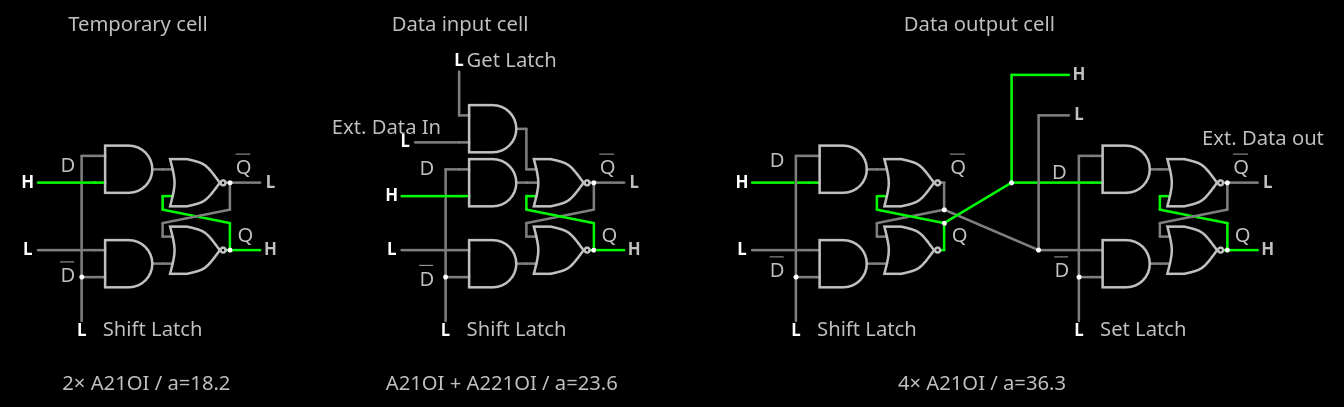
07/10/2026 at 12:55 • 0 commentsThe real circuit uses pairs of A21OI gates to create a latch.
![]()
Due to routing considerations (keeping the inter-latch wires on M2 but preventing crossings), the Q outputs actually go to /D and vice versa. It can create quite a confusion but since the latches come in pairs, the polarity is restored at every bit. It's easy to get confused though, particularly with the inter-macro connections.
![]() (don't mind the mislabeled inputs)
- So inside the pseudo-FF, the /Q output (controlled by SD) goes to the next Q input and vice versa.
- Outside, the /Q output of the SC slice goes to the Q inputs of the output buffer (controlled by Pulse2/Update) and the Q input of the next SD latch.
- In the layout, Q(SC) is tied to D(update), so the actual output is taken from /Q(update)
.
DTAP2-ULSR
Universal Latch-based Shift Register. Still not JTAG and fewer pins
 (don't mind the mislabeled inputs)