Close
0%
0%

DURACELL Max

What started as a regular AA battery turned into a 470Wh giant Duracell built completely from scratch.

Similar projects worth following
0 followers
Greetings, everyone, and welcome back!

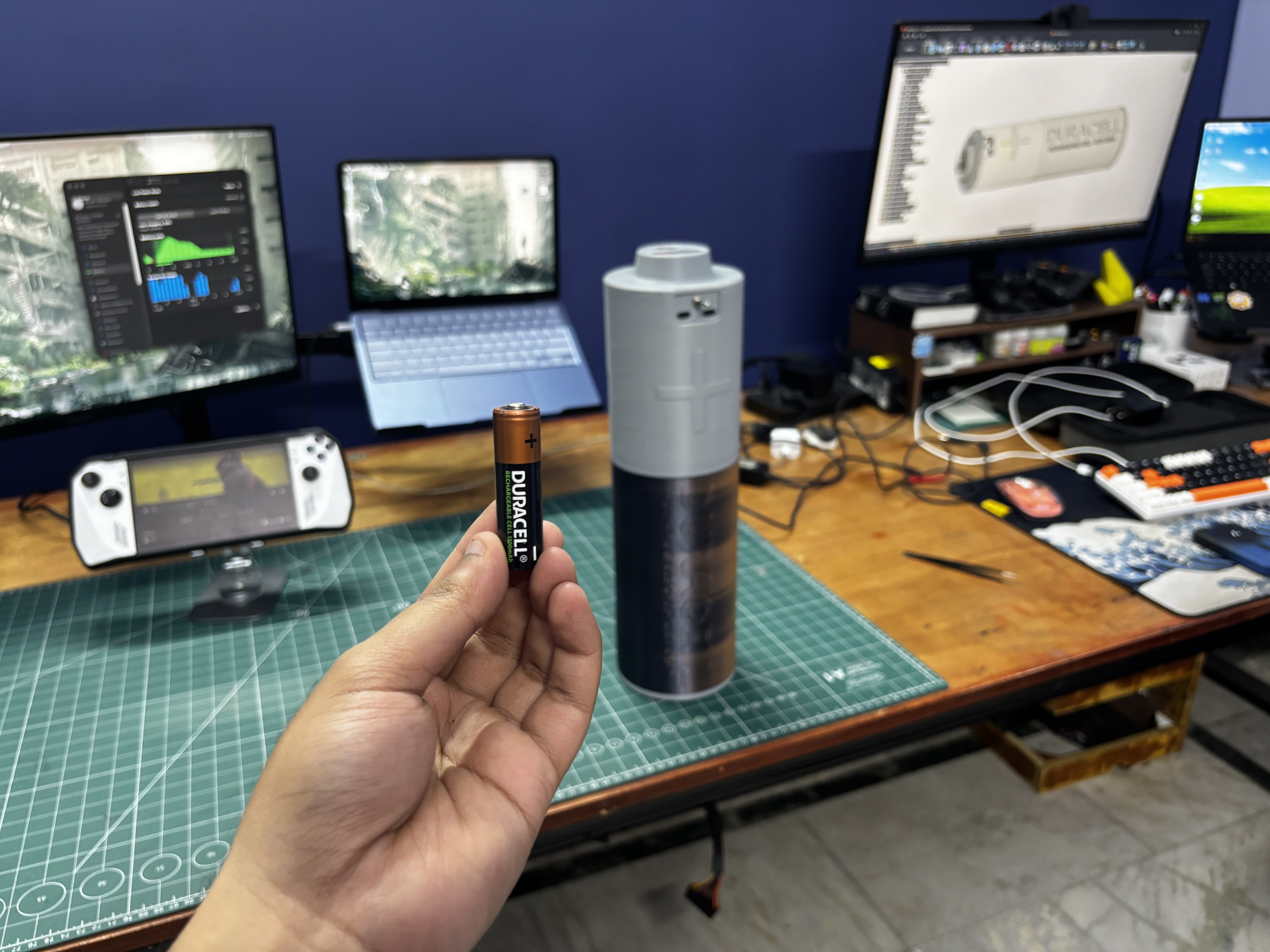
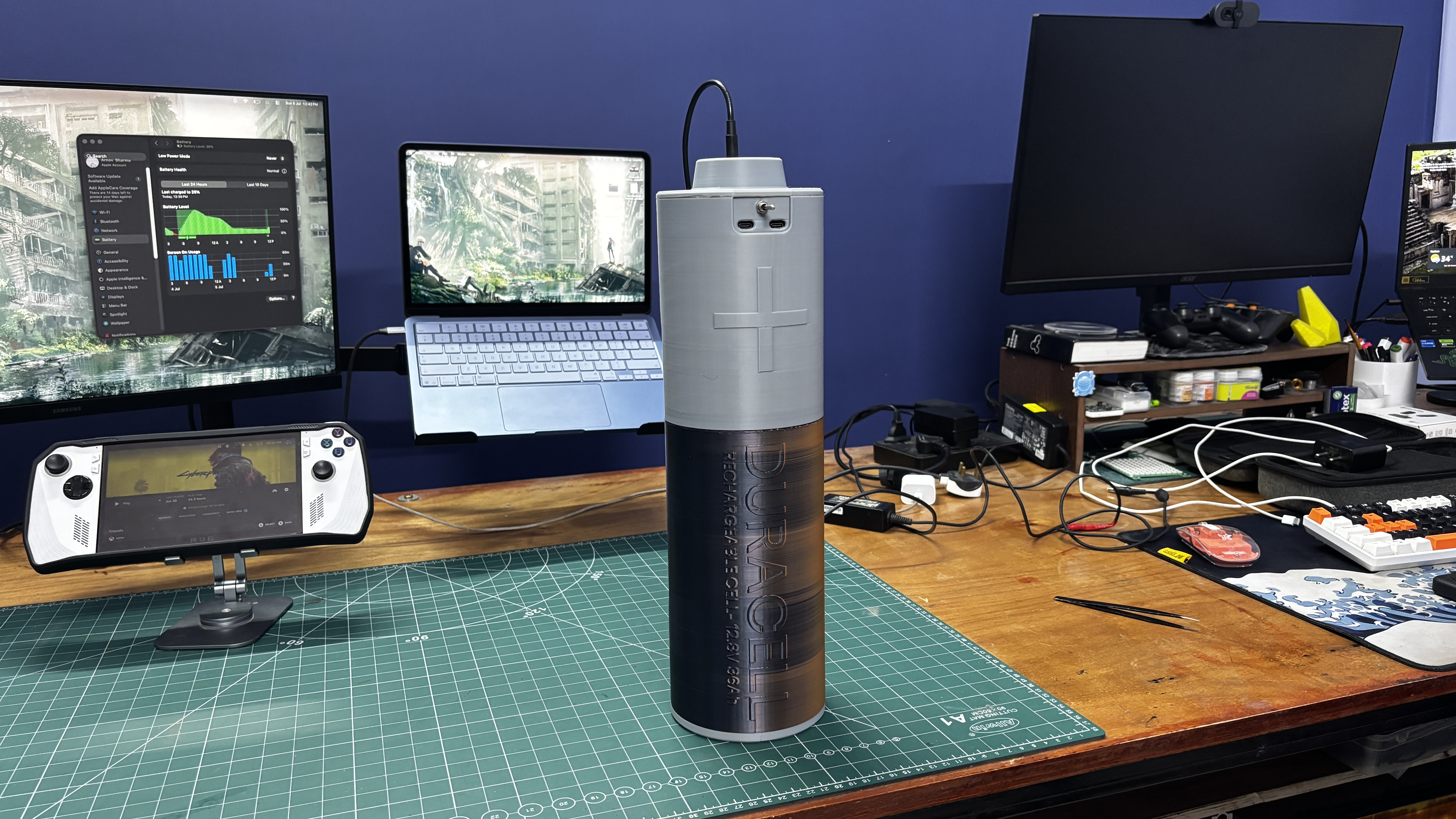
Here’s something biblically large. Meet DURACELL MAX, a giant Duracell battery that I made completely from scratch.

The idea behind this project was to build an emergency power source capable of providing a stable 12V output for various applications, such as driving an e-bike DC motor or powering other electronics projects.

I also included two separate 65W USB-C PD modules. Using a USB-C to USB-C cable, we can charge smartphones, tablets, handheld gaming consoles, and even laptops. This makes the battery pack a useful tool during a blackout, and it can also be carried on camping trips to charge devices or power 12V light sources and other equipment.

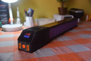
For the design of this project, I wanted to create something truly different from a regular battery pack enclosure. So, I modeled the entire battery pack to look like a ridiculously oversized Duracell AA battery.

Inside the enclosure is a custom-made battery pack built using LiFePO4 cells arranged in a 4S6P configuration. The completed battery pack has a nominal voltage of approximately 13.3V, a capacity of 36Ah, and stores roughly 470Wh of energy.

HARDWARE- LiFePO4 CELLS
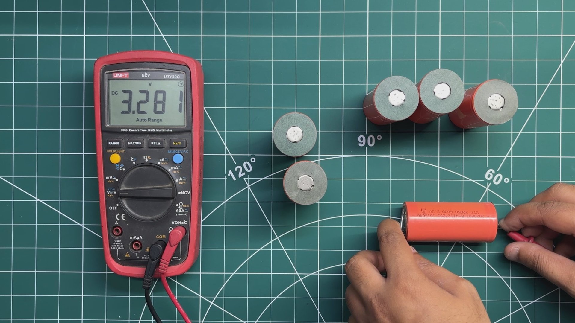
The main power source for this project is a set of LiFePO4 (Lithium Iron Phosphate) cells, each rated at 3.3V and 6000mAh. LiFePO4 cells are a great choice for this type of project because of their long cycle life, good thermal stability, and relatively safe chemistry compared to many other lithium battery types.

For this project, the idea is to build a 4S6P battery pack. This means six cells are first connected in parallel to increase the overall capacity, and four of these parallel groups are then connected in series to increase the pack voltage. In total, the battery pack uses 24 LiFePO4 cells.

Before assembling the battery pack, I checked the voltage of every individual cell using a multimeter and sorted them into groups with closely matched voltages. The cells used in this project were between approximately 3.270V and 3.280V.

Matching the cell voltages is especially important before connecting cells in parallel. When two cells with different voltages are directly connected in parallel, the higher-voltage cell will immediately start supplying current to the lower-voltage cell. Since lithium cells have very low internal resistance, even a relatively small voltage difference can potentially result in a high equalization current, causing excessive heat and creating a serious safety hazard.

Once cells are permanently connected in parallel, they behave electrically as a single, higher-capacity cell group because all the cells share the same voltage.

Series-connected groups work differently. In our 4S configuration, each parallel group can have a different voltage from the others because the BMS individually monitors the voltage of each series group through its balance connections. During charging, the BMS helps prevent individual series groups from exceeding their safe voltage limits and, if the BMS supports active or passive balancing, helps keep the series groups balanced.

However, the BMS cannot individually monitor or control each cell inside a parallel group. This is why checking and closely matching the voltage of all cells before connecting them in parallel is an important step in building the battery pack safely.

After checking all 24 cells and confirming that their voltages were within the required range, they were ready to be arranged inside the custom battery holders and connected to form the 4S6P battery pack.

HARDWARE- BMS
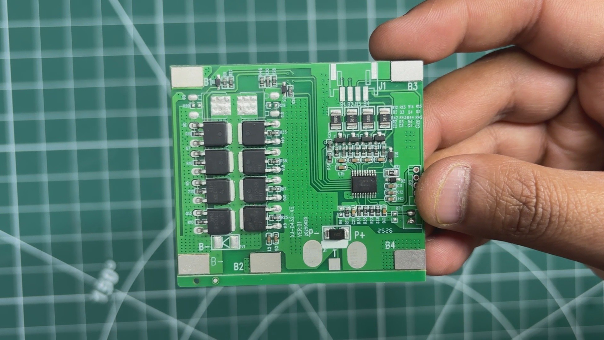
For managing and protecting the battery pack, I am using a 4S 20A BMS specifically designed for LiFePO4 cells. The BMS supports a 4S configuration with a nominal pack voltage of 12.8V and a continuous discharge current of up to 20A.

The main purpose of the BMS is to protect the LiFePO4 cells during charging and discharging. It provides essential safety features, including overcharge, over-discharge, overcurrent, and short-circuit protection.

The BMS continuously monitors the voltage of each series cell group and disconnects the battery pack if the voltage exceeds or drops below the safe operating limits.

With its 20A continuous discharge capability, this BMS is suitable for our 4S6P battery pack and allows us to safely charge the battery and power various devices connected to the output.

HARDWARE- PD MODULE
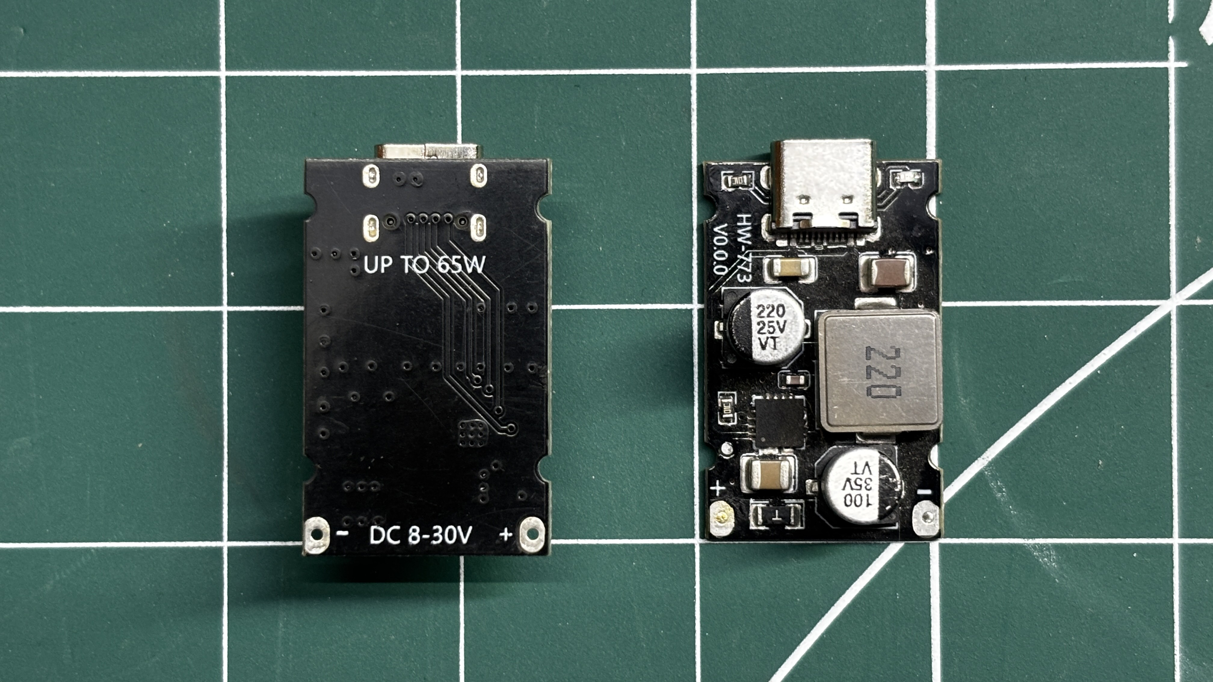
For the USB-C power output, I am using a 65W PD fast-charging module. This is a compact and highly efficient DC-DC step-down converter that supports multiple fast-charging protocols, including PD3.1 (PPS), QC3.0, Huawei SCP/FCP, and Samsung AFC.

The module accepts an input voltage of 8V to 30V and can provide up to 65W...

Read more »
DURACELL v12.step

step - 6.13 MB - 07/08/2026 at 09:12

Download

TOP2.stl

Standard Tesselated Geometry - 607.02 kB - 07/08/2026 at 09:12

Download

Upper shell.stl

Standard Tesselated Geometry - 274.30 kB - 07/08/2026 at 09:12

Download

JIG1.stl

Standard Tesselated Geometry - 4.77 kB - 07/08/2026 at 09:11

Download

PCB 01 parts - PCB_l.cnv

cnv - 3.30 kB - 07/08/2026 at 09:11

Download

View all 19 files

  • 1
    NICKEL STRIP ASSEMBLY

    For connecting the cells in parallel, the best method is to use a spot welder with nickel strips.

    Directly soldering wires or strips to the terminals of lithium cells is generally considered bad practice, as the excessive heat generated during soldering can damage the cells, reduce their capacity, or, in extreme cases, create a serious safety hazard. This is why spot welding is commonly used for assembling lithium battery packs.

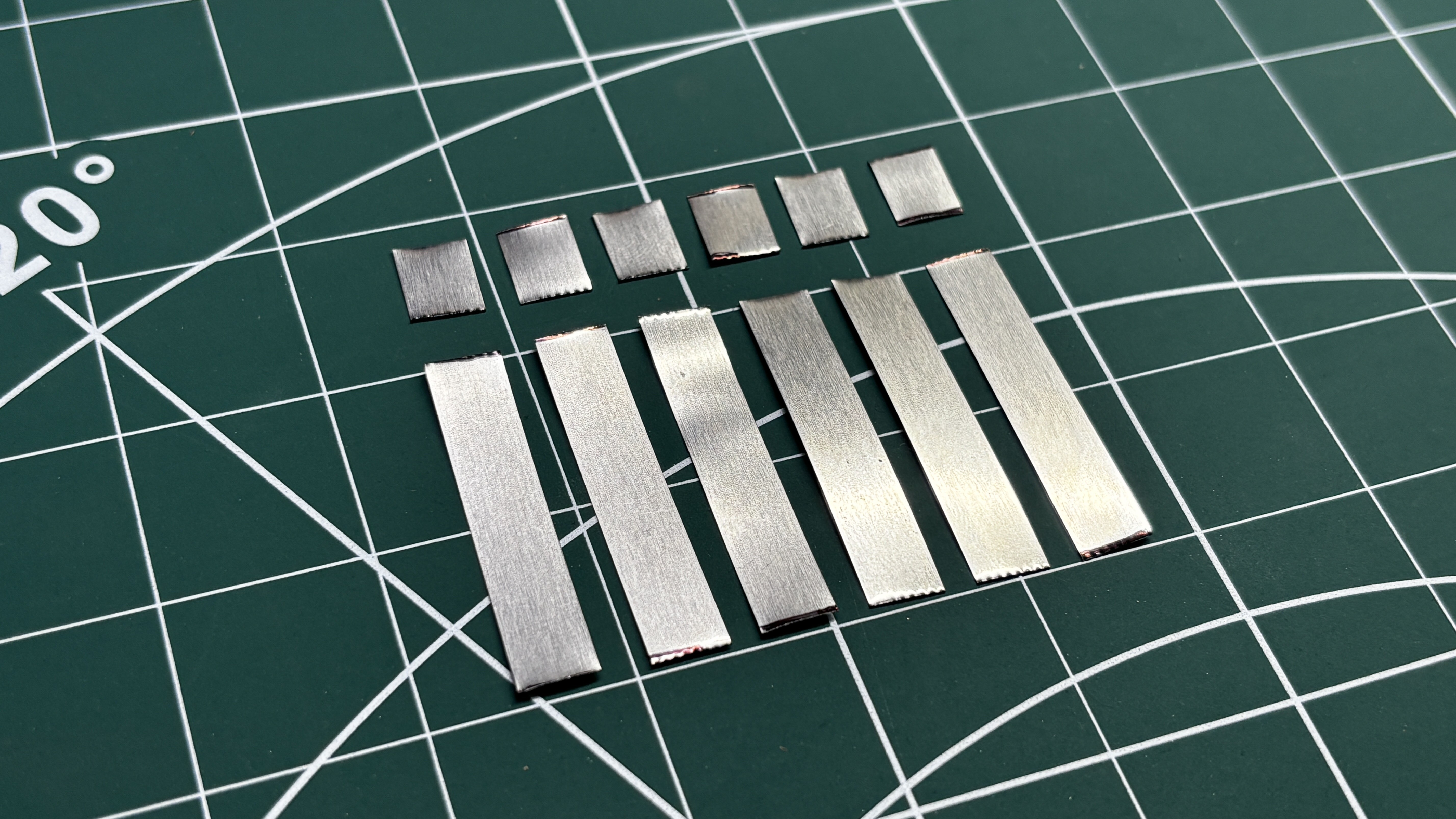
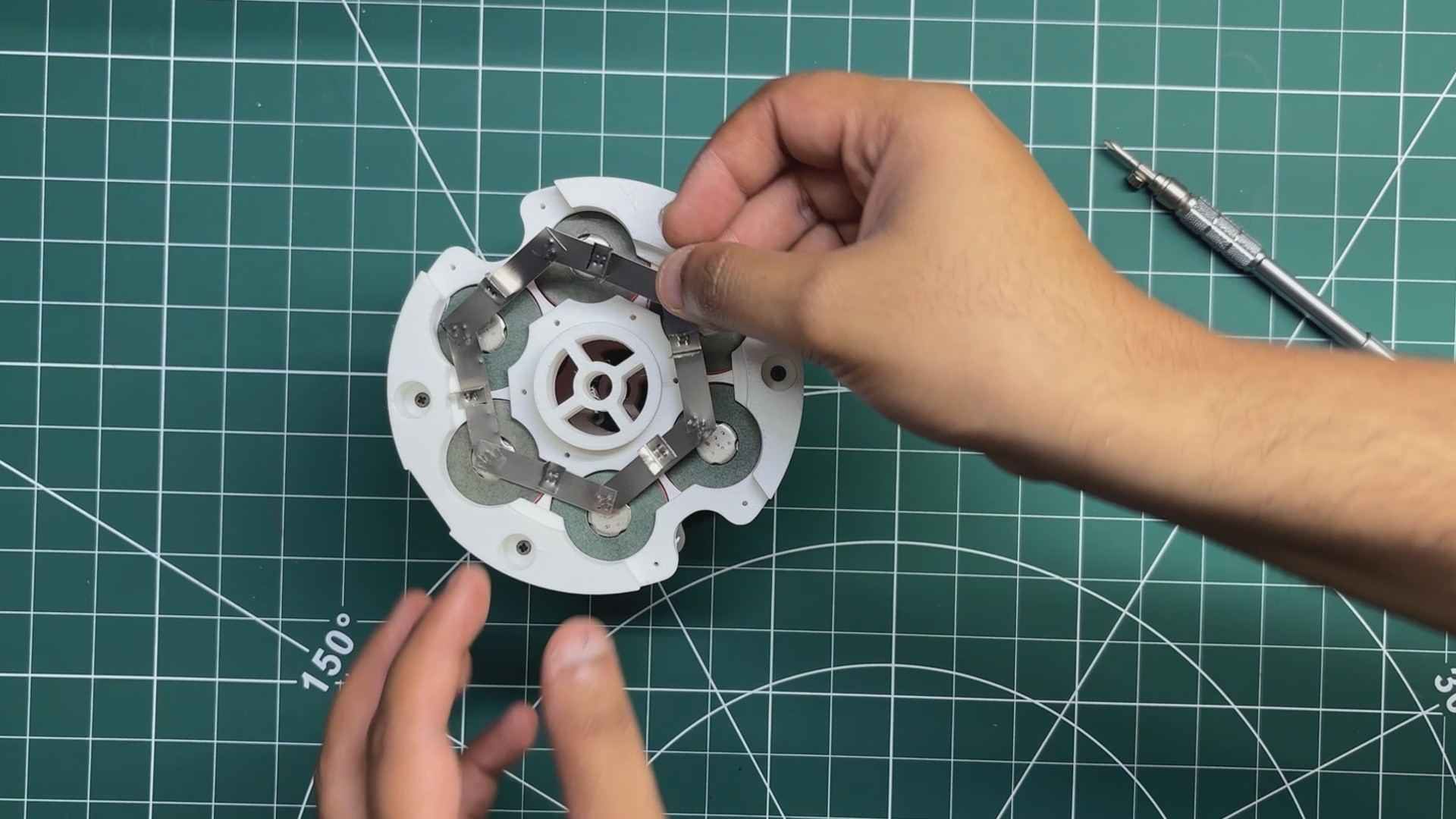
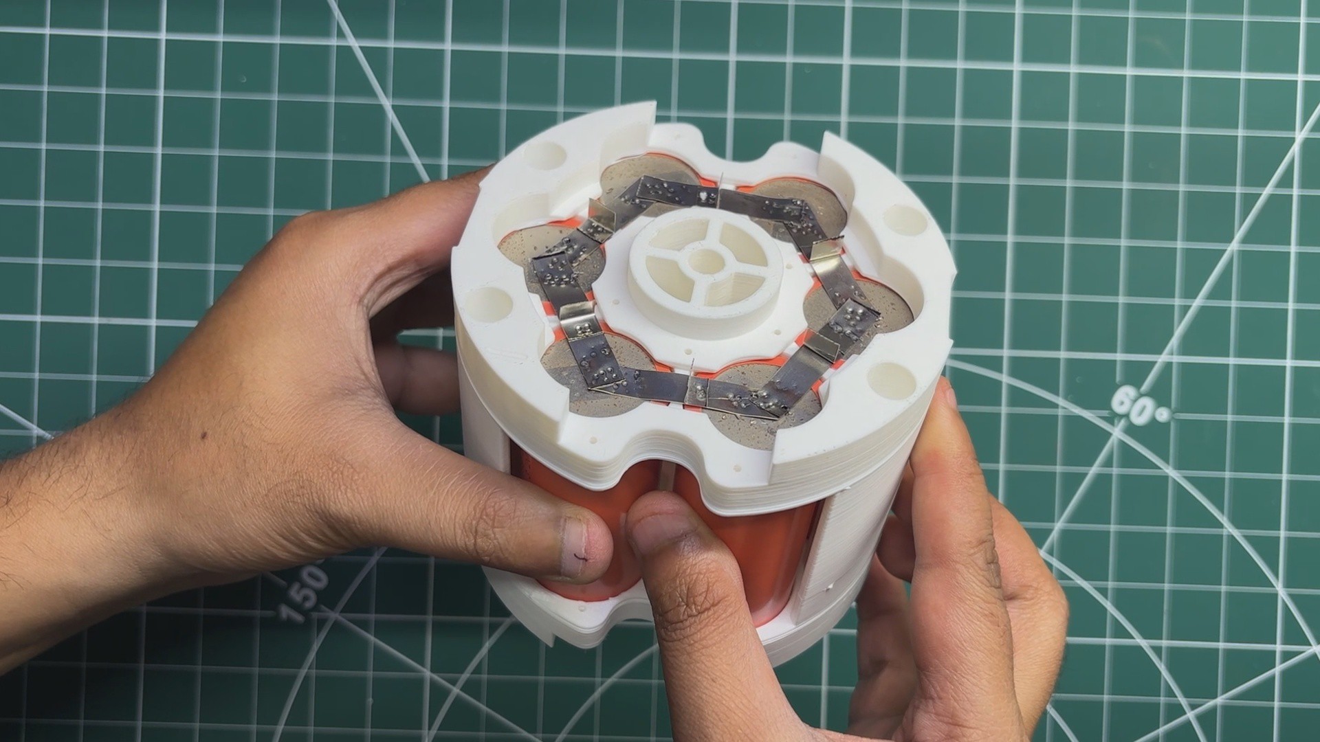
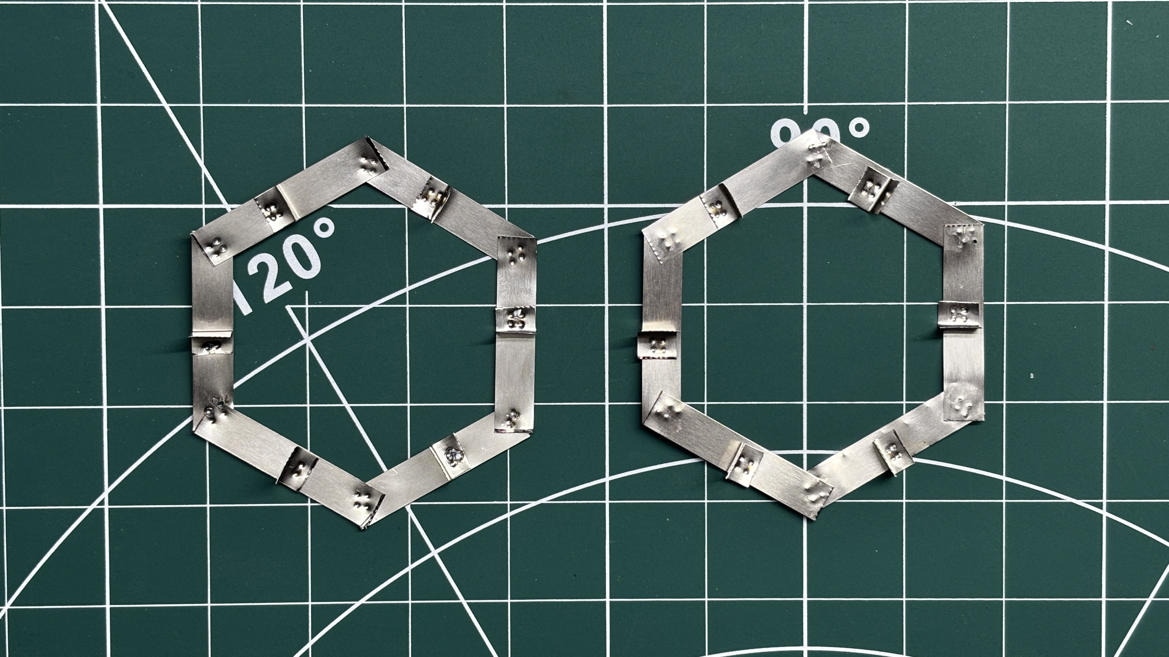
    One challenge I faced was that, because of the unusual cell arrangement used in this project, standard nickel strips would not work well. Therefore, I had to design a custom hexagonal nickel strip setup.

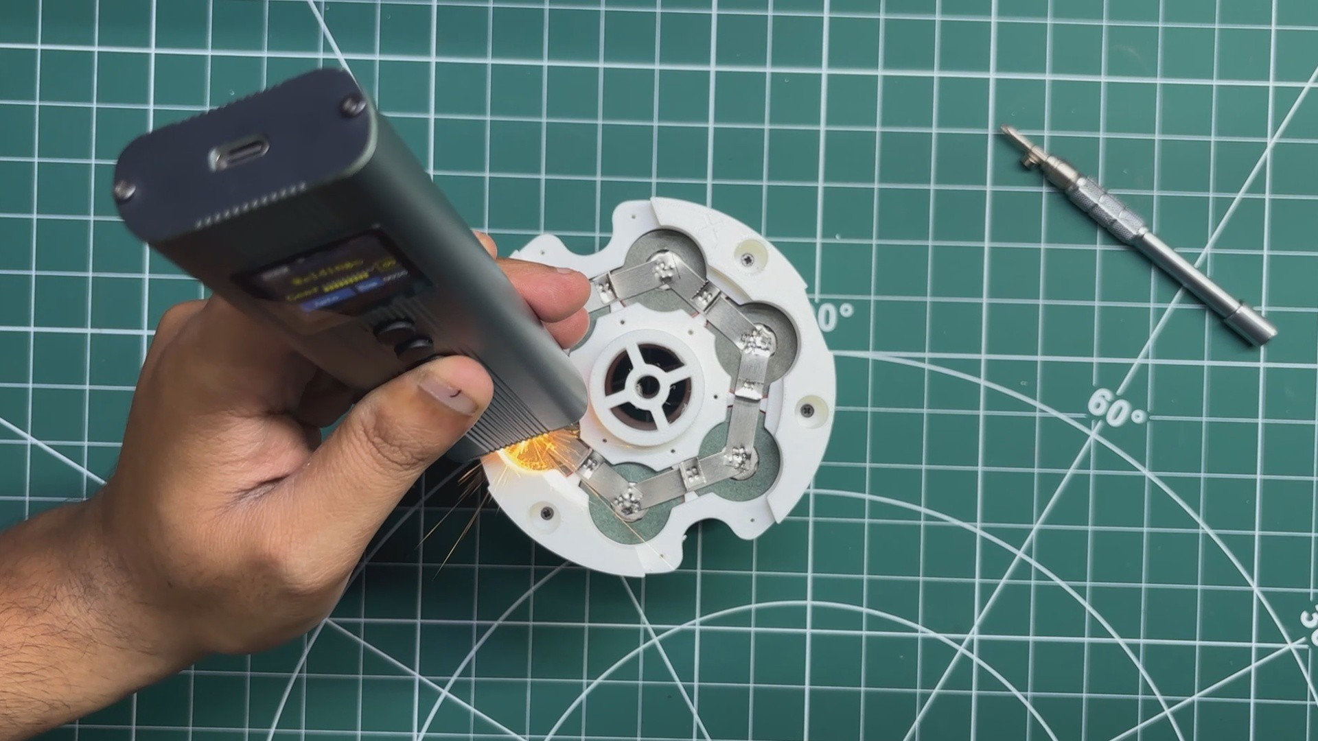
    For the spot-welding process, I got myself a portable spot welder.

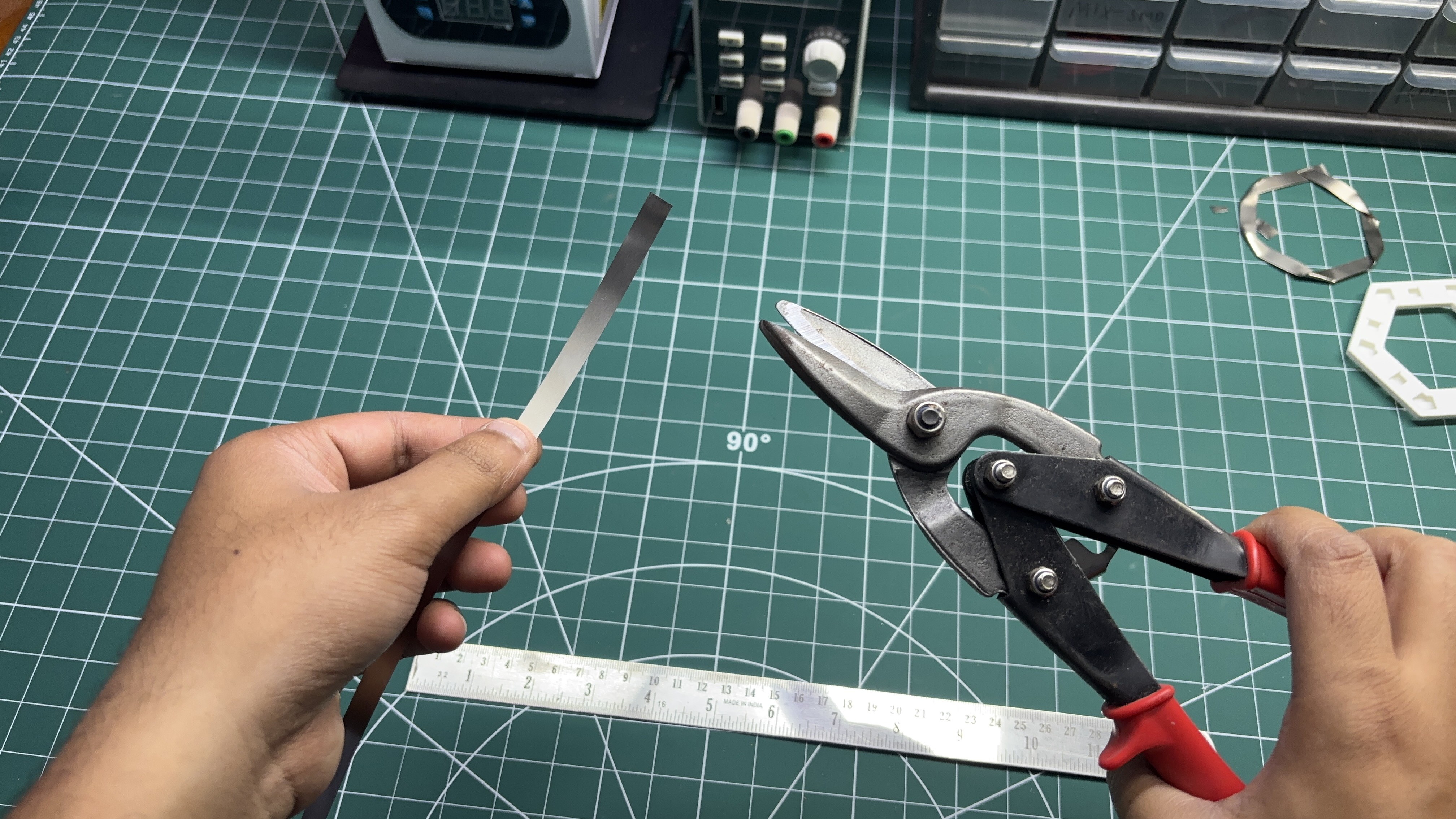
    • The process begins by cutting the nickel strips into two different sizes, as mentioned in the Strip Size PDF. The longer 39mm strips are used to create the hexagonal shape for connecting the cells, while the smaller 10mm strips are used to create the L-shaped section that will allow us to mount the PCB above the nickel strip.
    • Using a custom 3D-printed jig, we first place the 39mm nickel strips into their designated slots to form a hexagonal shape. The second half of the jig is then placed on top to hold all the strips securely in position.
    • Next, using the portable spot welder, we spot-weld all the individual strips together, resulting in a single hexagonal nickel strip.
    • We then place the L-shaped section in its designated position on top of the hexagonal nickel strip.
    • The second half of the jig is placed over the entire setup to hold everything securely in position, and the L-shaped section is spot-welded to the hexagonal nickel strip.

    The result of this process is a custom hexagonal nickel strip that will be used to create the parallel connections in our battery pack.

    For this project, we need a total of eight custom hexagonal nickel strips.

  • 2
    PARALLEL PACK ASSEMBLY
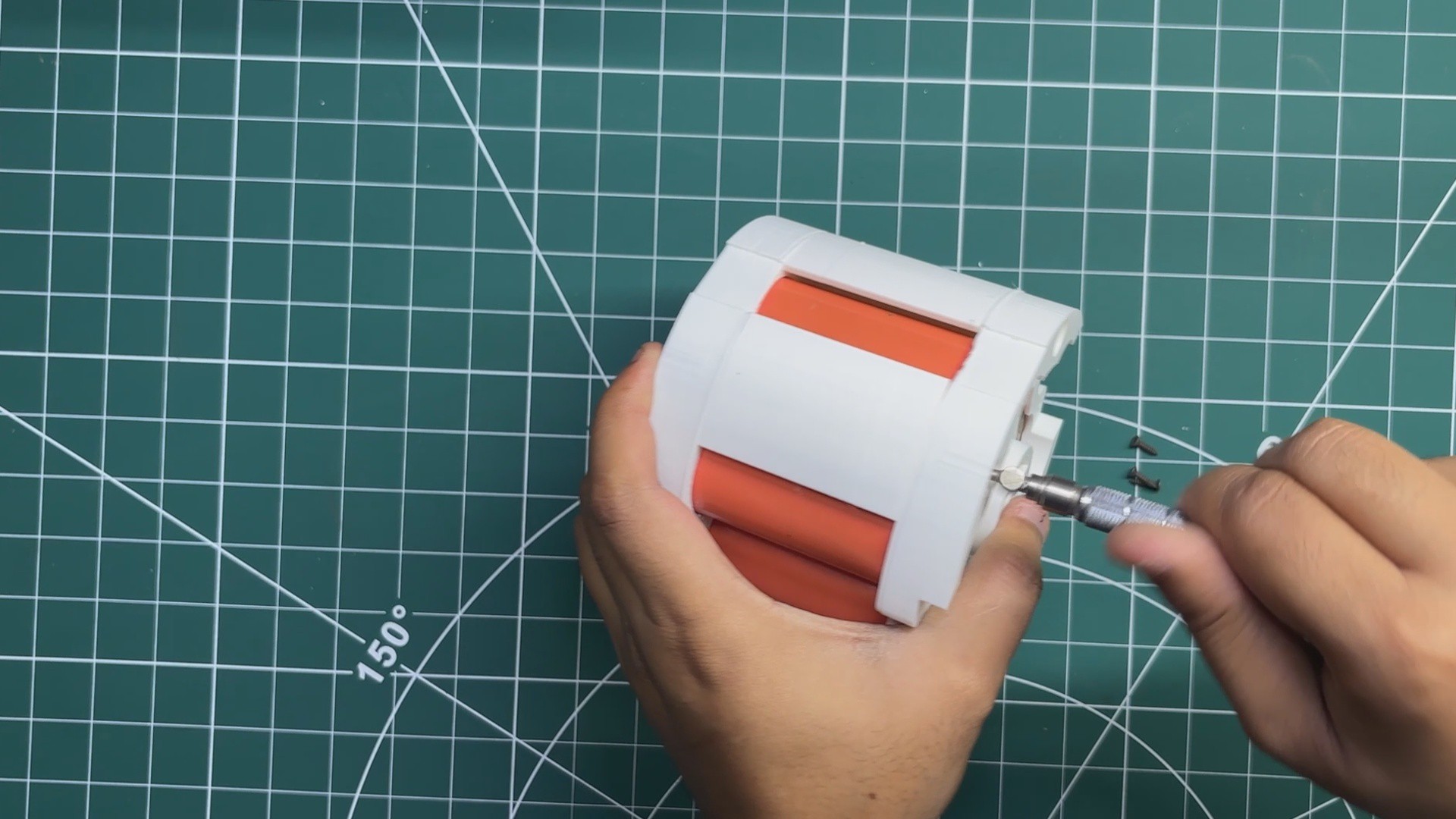
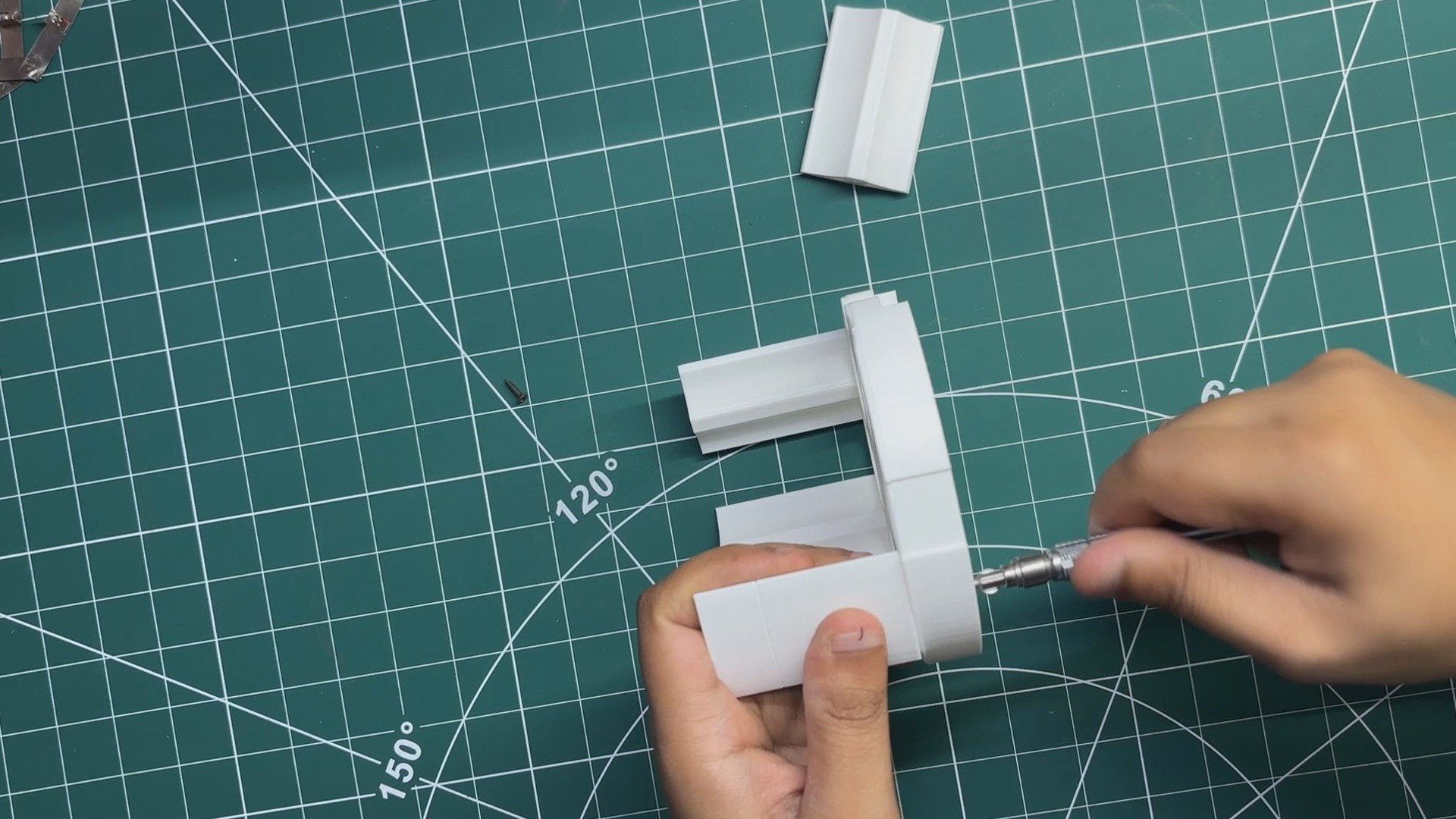
    • We begin the assembly process by first installing the four mid-support pieces onto the bottom cell holder and securing them in place using M2 screws.
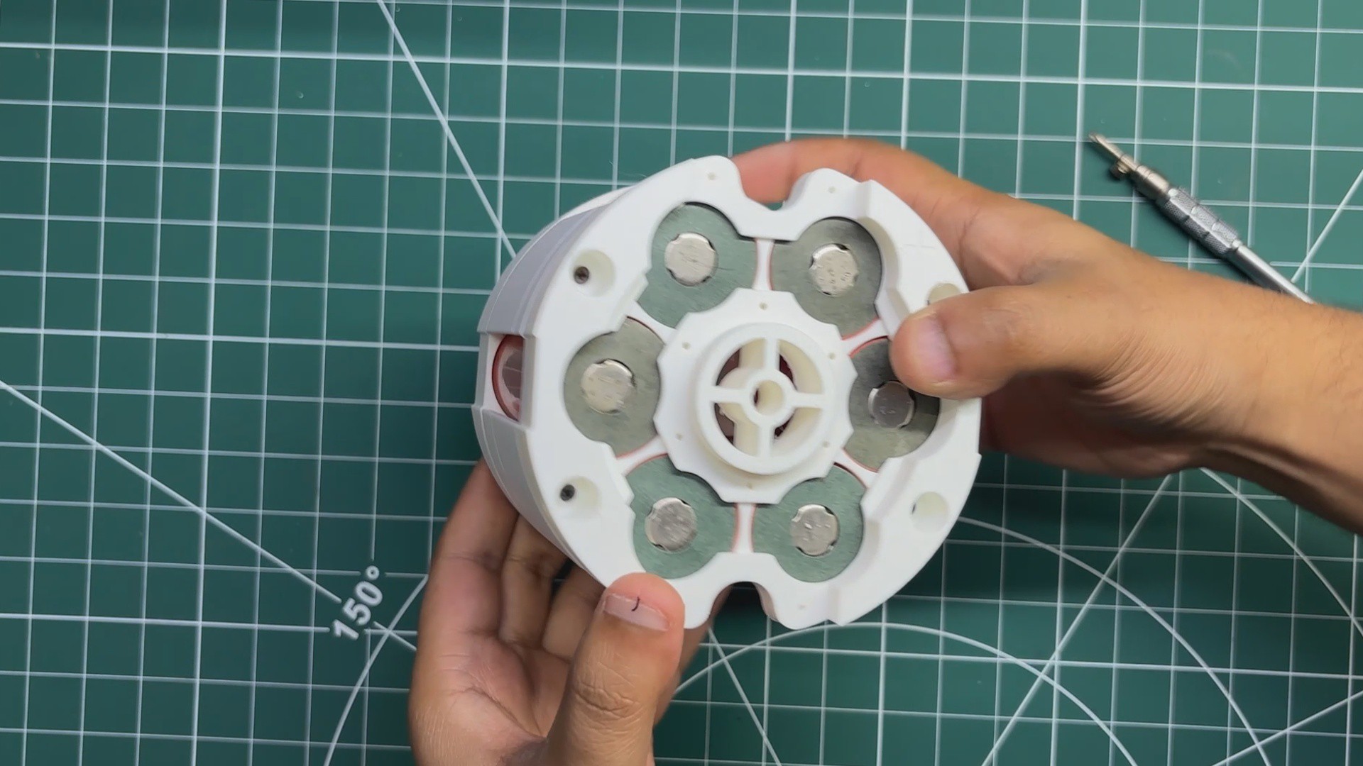
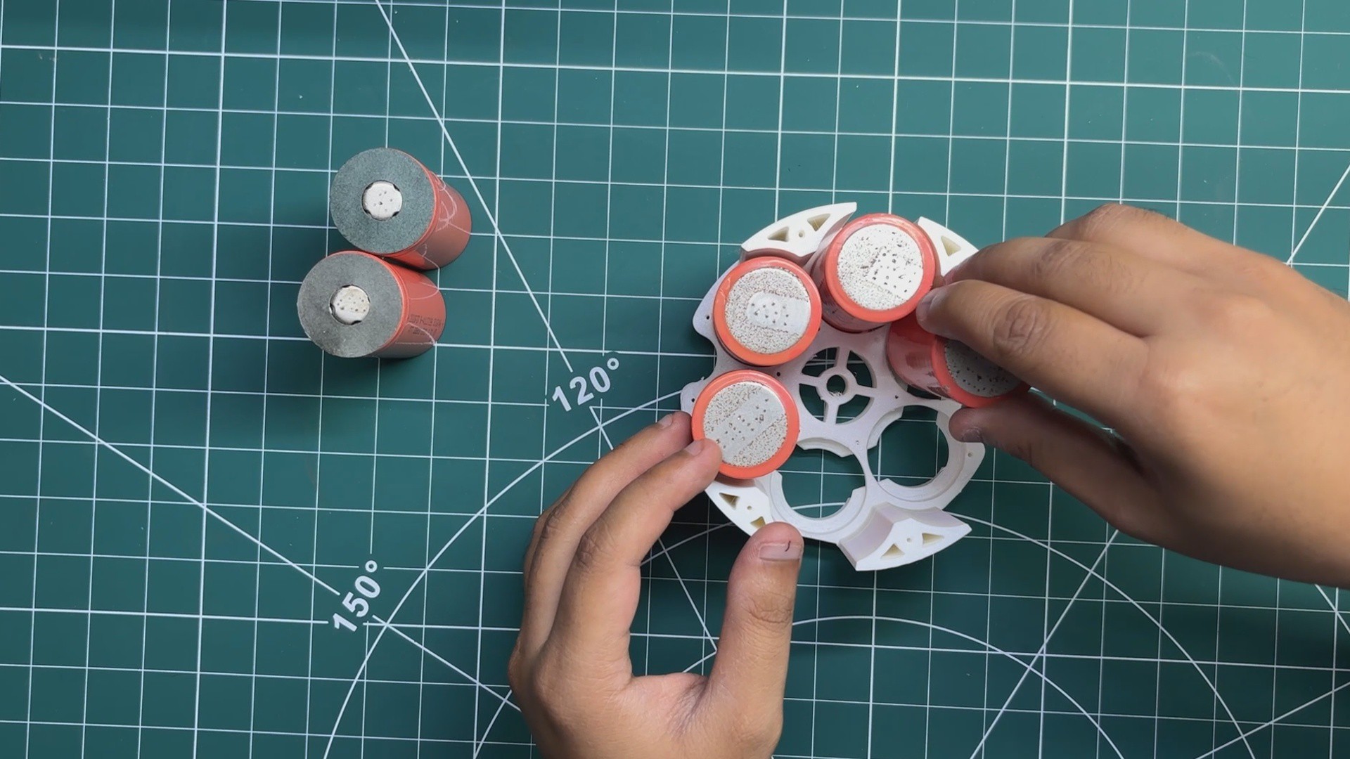
    • Next, the LiFePO4 cells are inserted into the bottom holder with the negative terminals facing downward and the positive terminals facing upward.
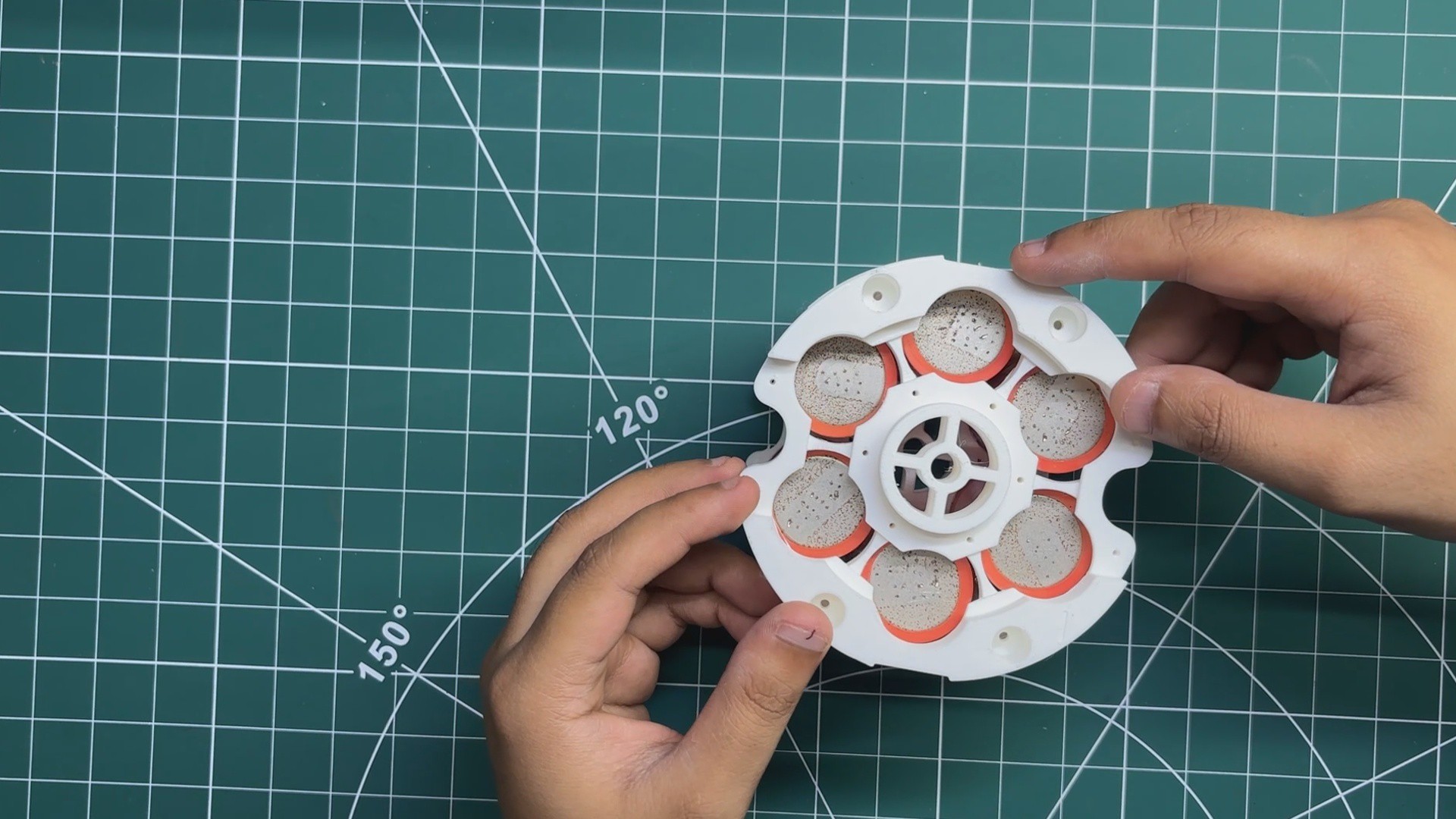
    • The top cell holder is then placed over the cells and secured to the mid-support pieces using M2 screws. This firmly locks all six cells in place, completing the mechanical assembly of one parallel cell holder.
    • The electrical connections are made next. We begin by placing the custom hexagonal nickel strip on the positive side of the cell holder. Using a spot welder, the nickel strip is welded to the terminals of all six cells, electrically connecting them in parallel.
    • The same process is then repeated on the negative side of the battery pack using another hexagonal nickel strip.
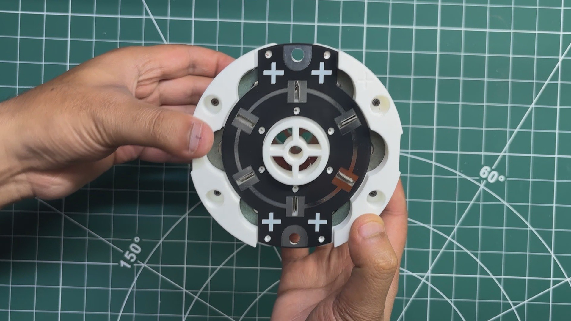
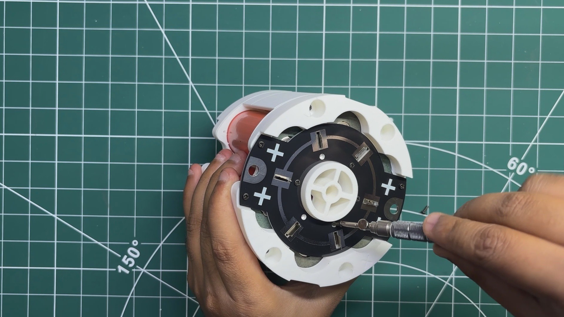
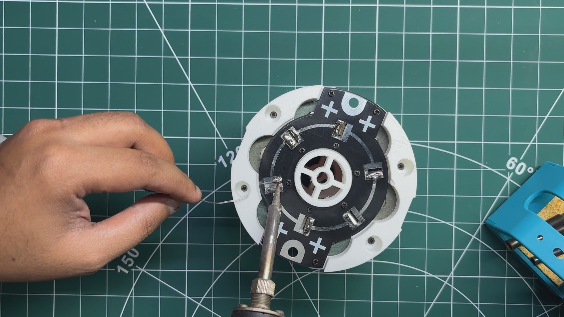
    • Once both nickel strips are spot-welded, the connection PCBs are placed over the nickel strips and secured using M2 screws. Finally, the nickel strips are soldered to the PCBs, creating a solid electrical connection between the cells and the connection boards.
    • The same process is done on both the positive and negative sides of the cell holder, completing one fully assembled parallel battery module.
  • 3
    TEST

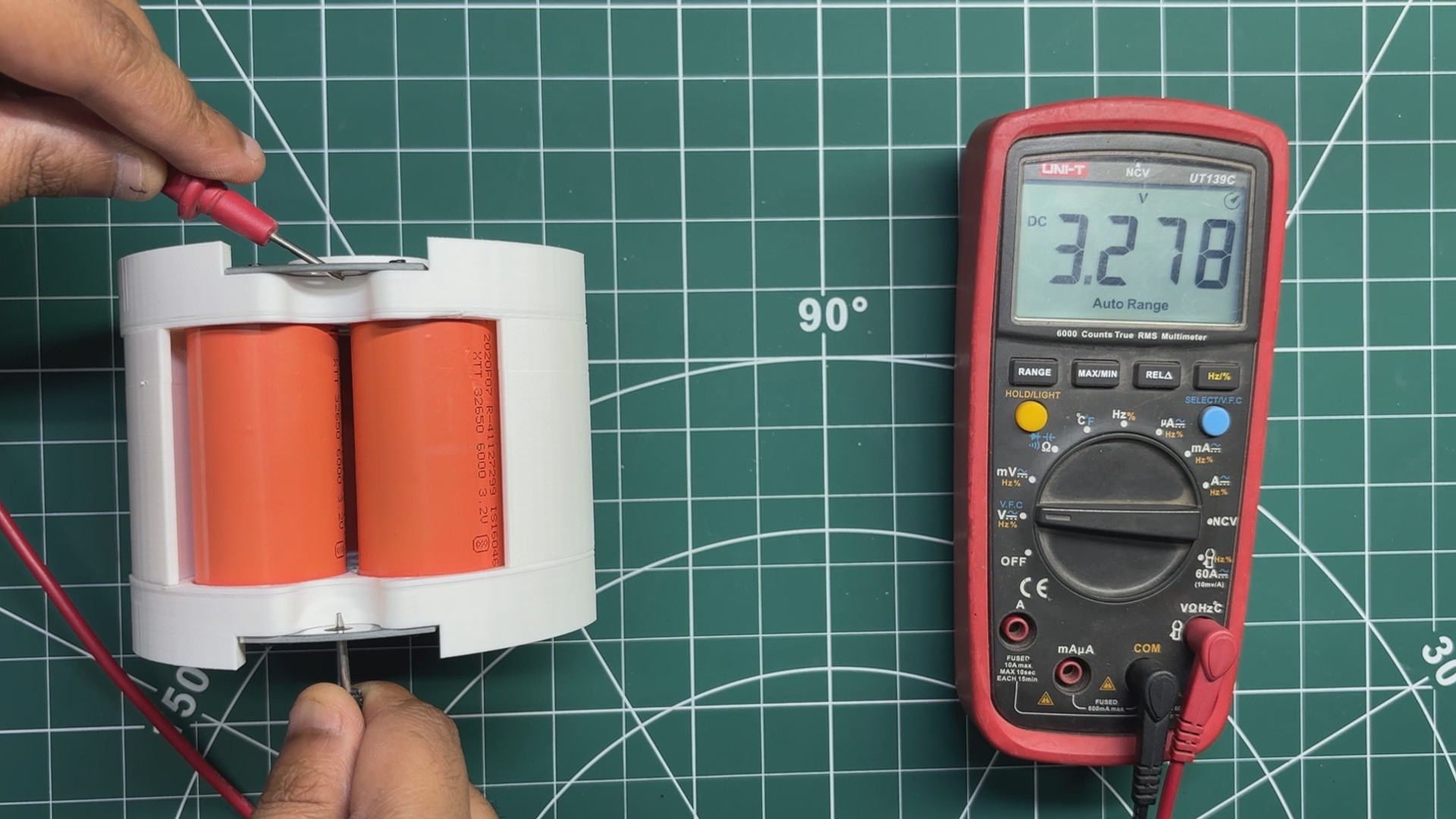
    To verify that everything was assembled correctly, I measured the output voltage of the completed parallel cell holder using a multimeter. The measured voltage was approximately 3.27V, confirming that all six cells were properly connected in parallel and the assembly was functioning as expected.

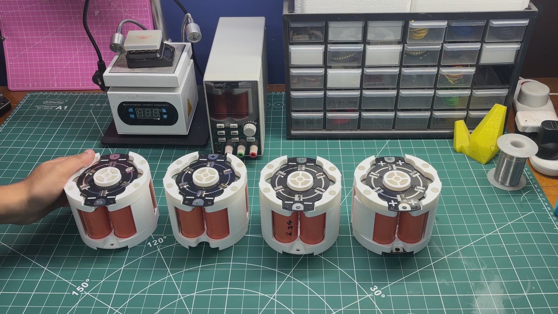
    Since the final battery pack requires four identical parallel cell holders, I repeated the entire assembly process three more times until all four modules were complete and ready to be connected in series.

View all 11 instructions

Enjoy this project?

Share

Discussions

Similar Projects

Does this project spark your interest?

Become a member to follow this project and never miss any updates