For connecting the cells in parallel, the best method is to use a spot welder with nickel strips.
Directly soldering wires or strips to the terminals of lithium cells is generally considered bad practice, as the excessive heat generated during soldering can damage the cells, reduce their capacity, or, in extreme cases, create a serious safety hazard. This is why spot welding is commonly used for assembling lithium battery packs.
One challenge I faced was that, because of the unusual cell arrangement used in this project, standard nickel strips would not work well. Therefore, I had to design a custom hexagonal nickel strip setup.
For the spot-welding process, I got myself a portable spot welder.
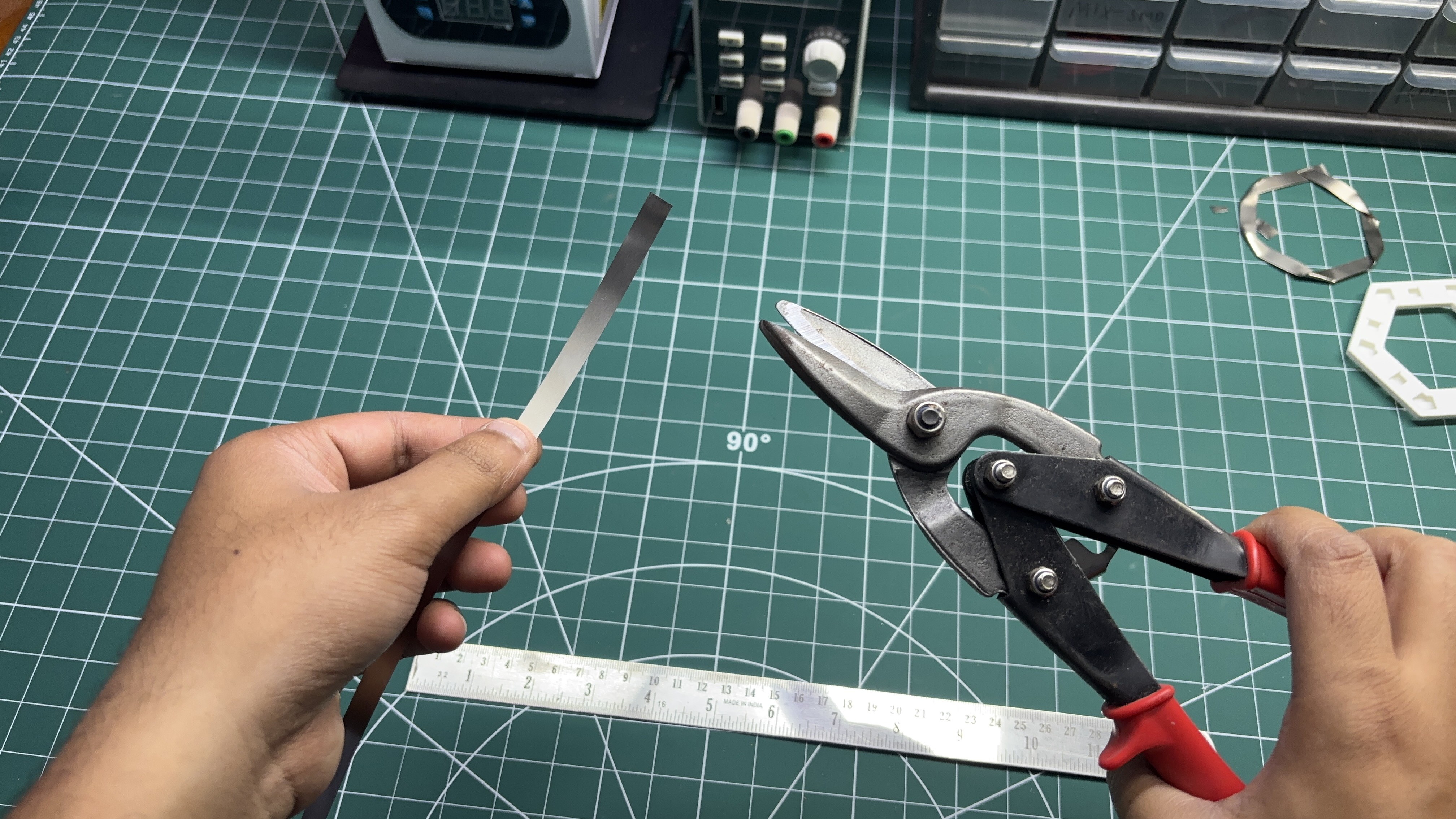
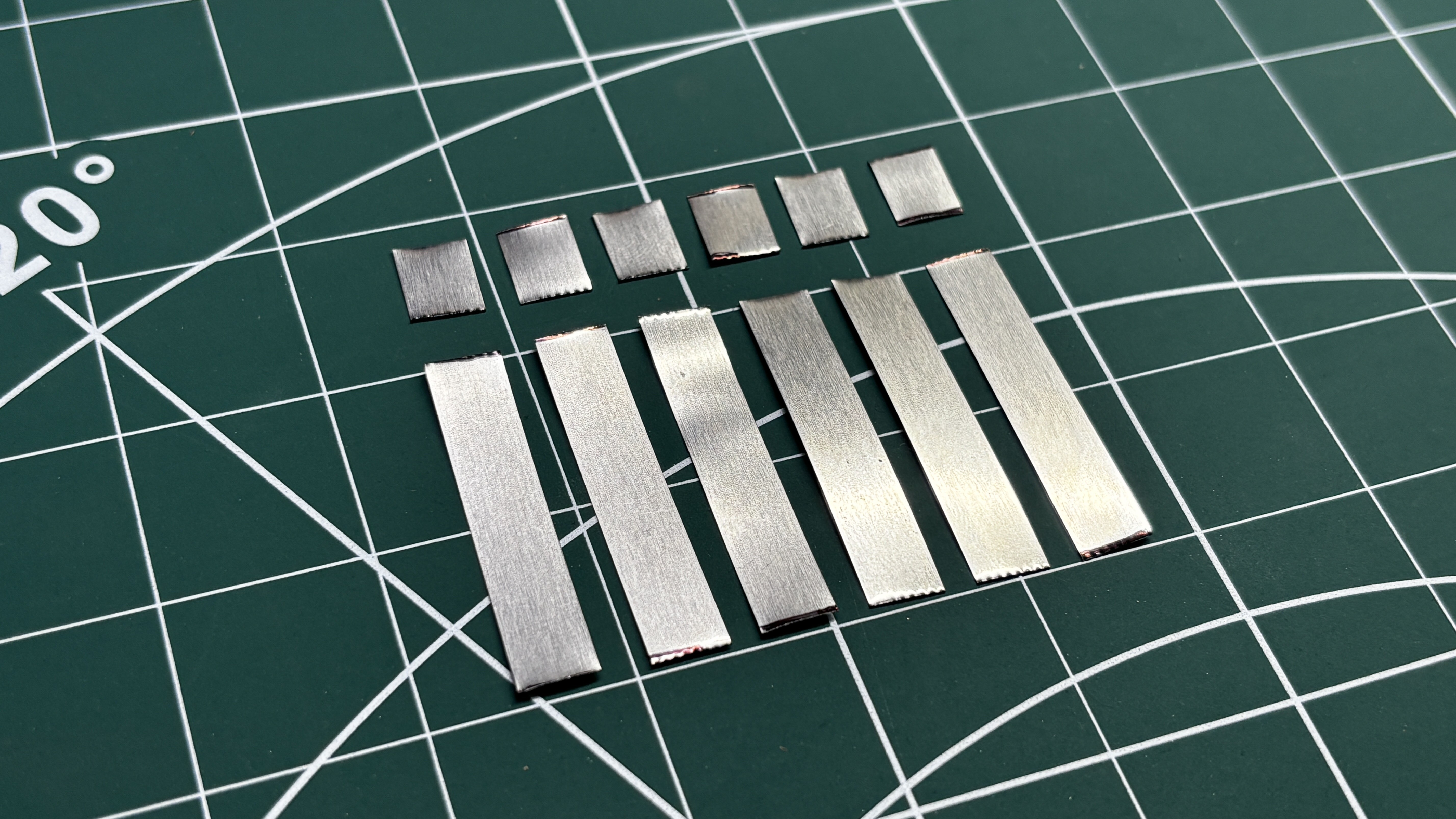
The process begins by cutting the nickel strips into two different sizes, as mentioned in the Strip Size PDF. The longer 39mm strips are used to create the hexagonal shape for connecting the cells, while the smaller 10mm strips are used to create the L-shaped section that will allow us to mount the PCB above the nickel strip.
Using a custom 3D-printed jig, we first place the 39mm nickel strips into their designated slots to form a hexagonal shape. The second half of the jig is then placed on top to hold all the strips securely in position.
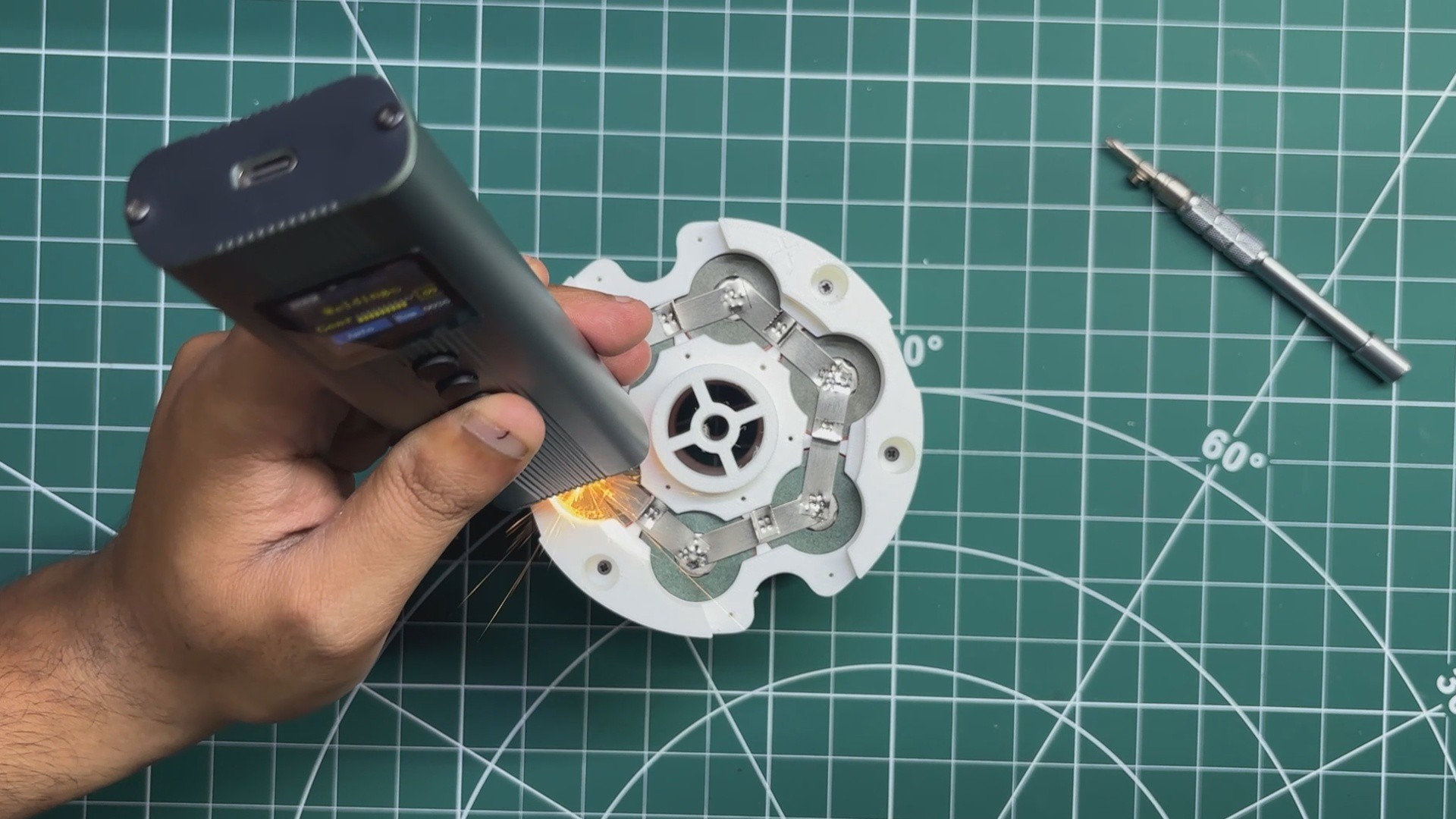
Next, using the portable spot welder, we spot-weld all the individual strips together, resulting in a single hexagonal nickel strip.
We then place the L-shaped section in its designated position on top of the hexagonal nickel strip.
The second half of the jig is placed over the entire setup to hold everything securely in position, and the L-shaped section is spot-welded to the hexagonal nickel strip.
The result of this process is a custom hexagonal nickel strip that will be used to create the parallel connections in our battery pack.
For this project, we need a total of eight custom hexagonal nickel strips.
2
PARALLEL PACK ASSEMBLY
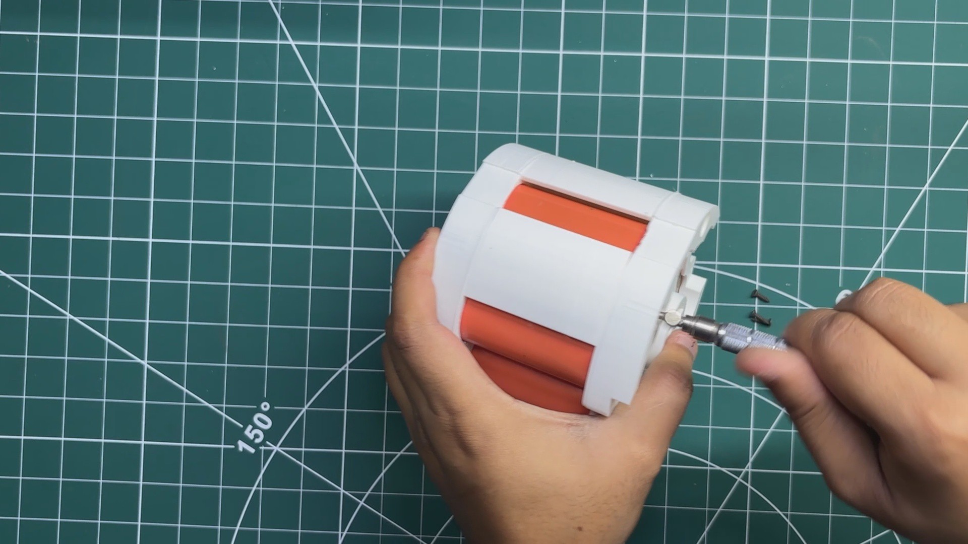
We begin the assembly process by first installing the four mid-support pieces onto the bottom cell holder and securing them in place using M2 screws.
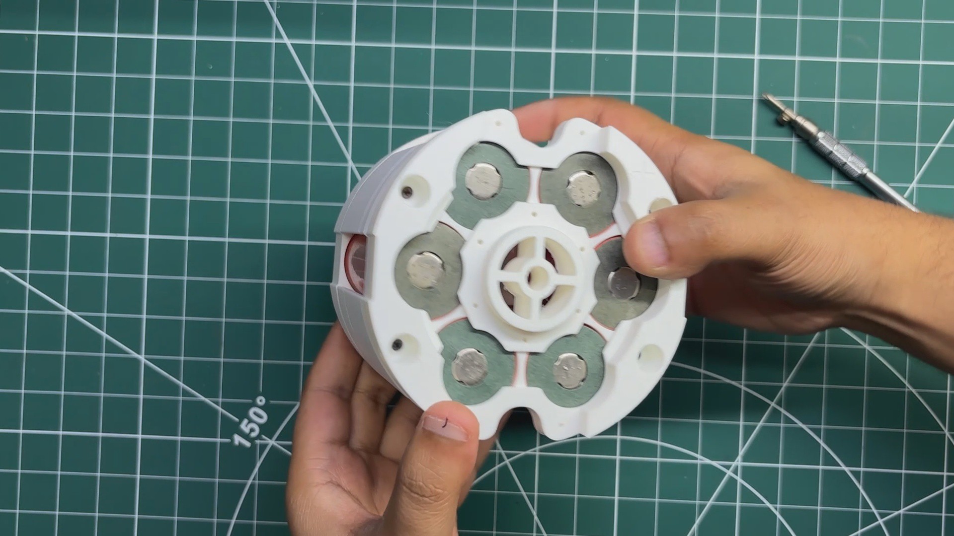
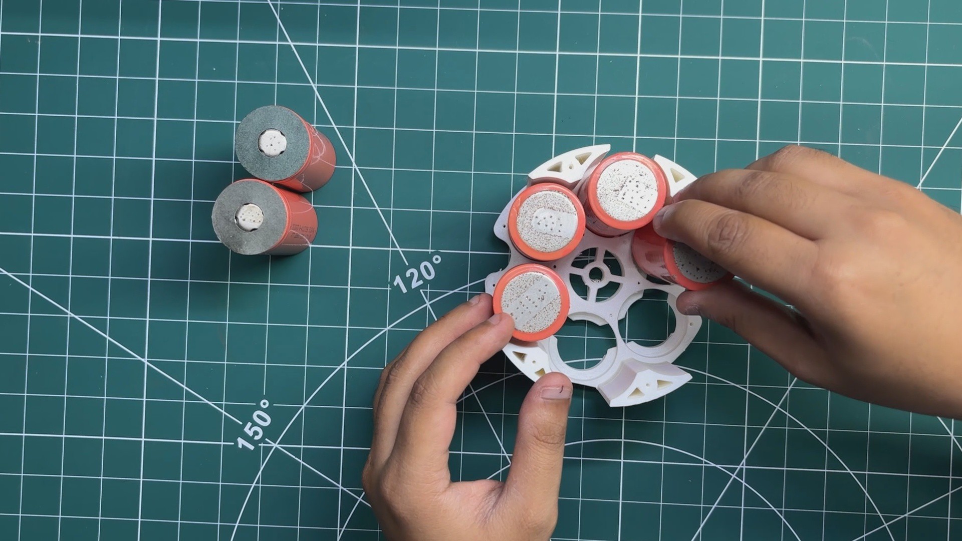
Next, the LiFePO4 cells are inserted into the bottom holder with the negative terminals facing downward and the positive terminals facing upward.
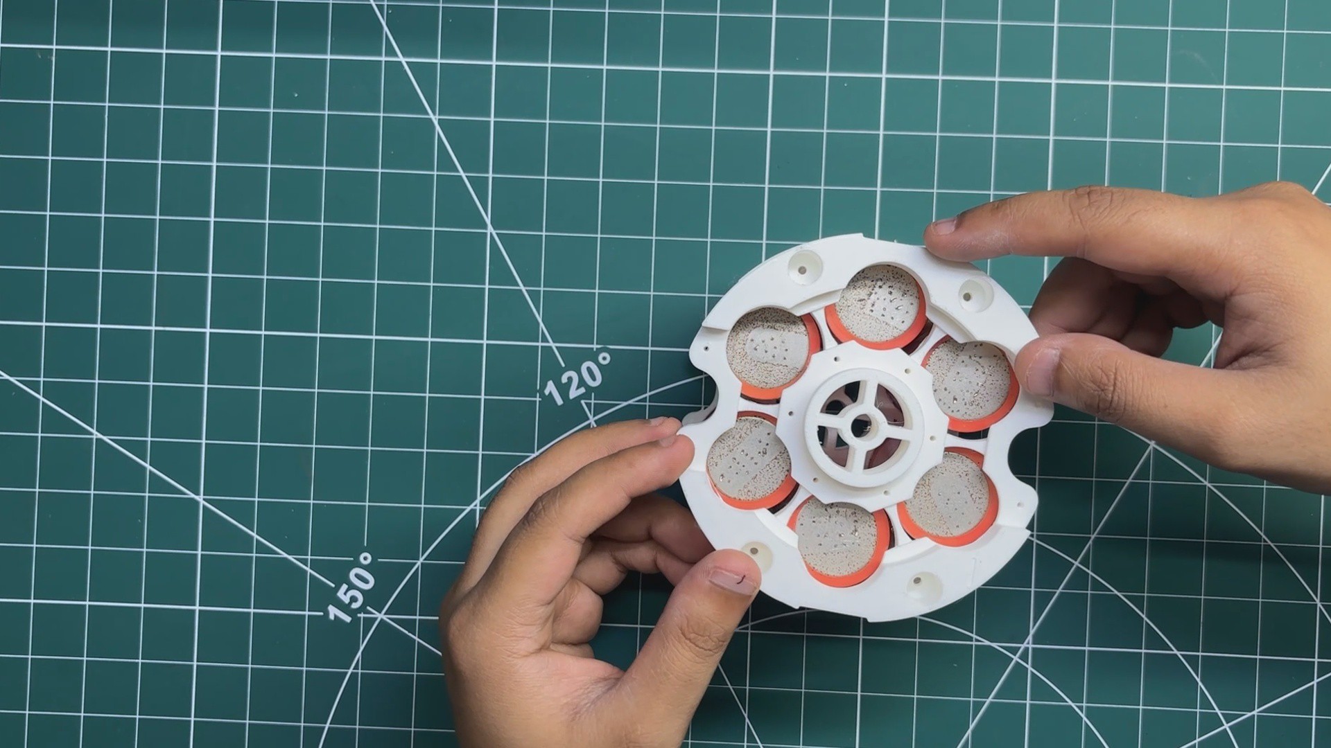
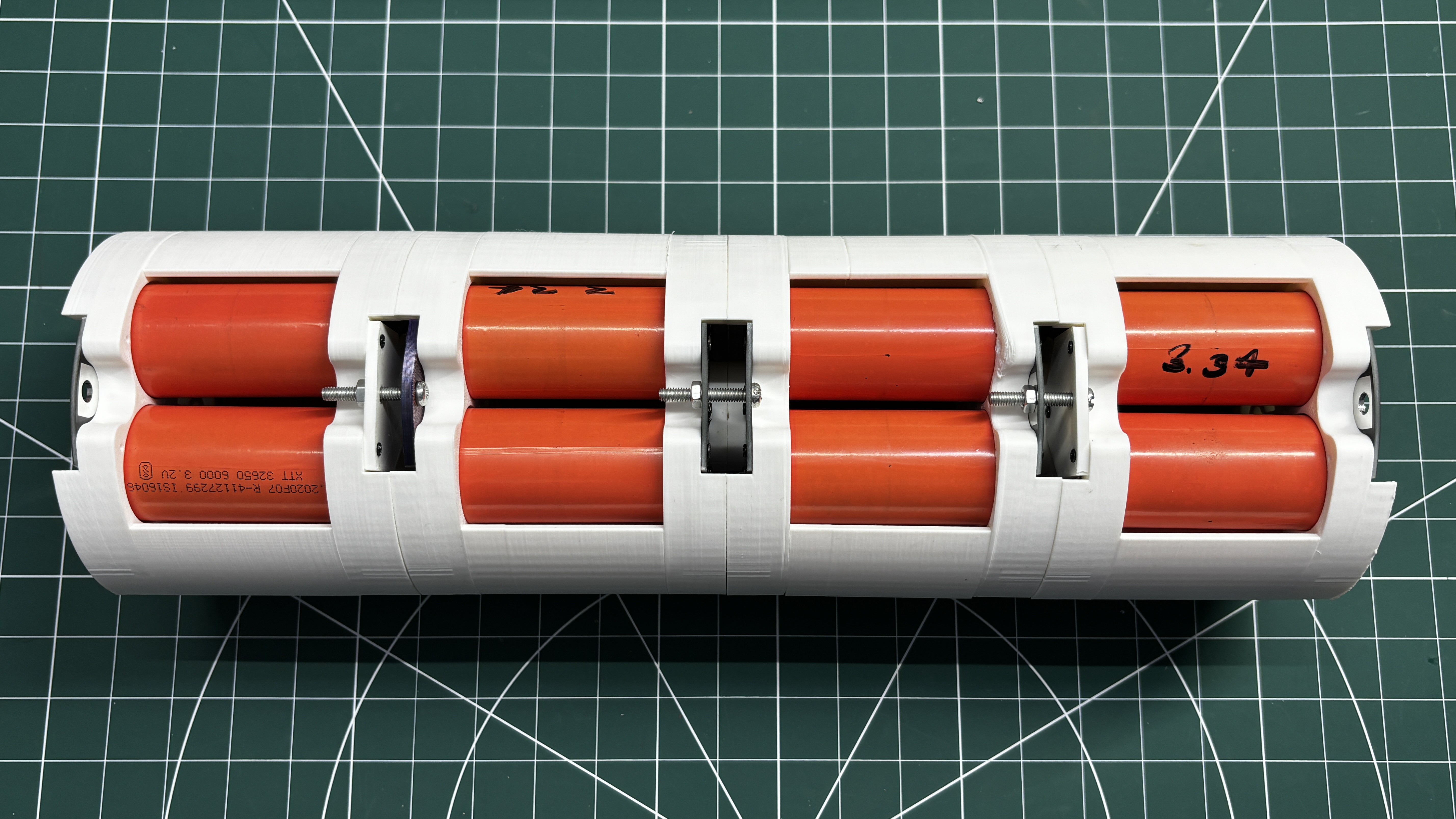
The top cell holder is then placed over the cells and secured to the mid-support pieces using M2 screws. This firmly locks all six cells in place, completing the mechanical assembly of one parallel cell holder.
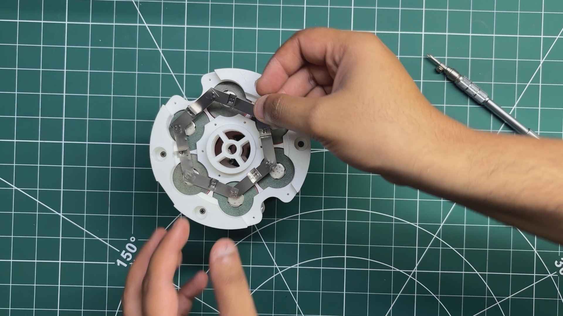
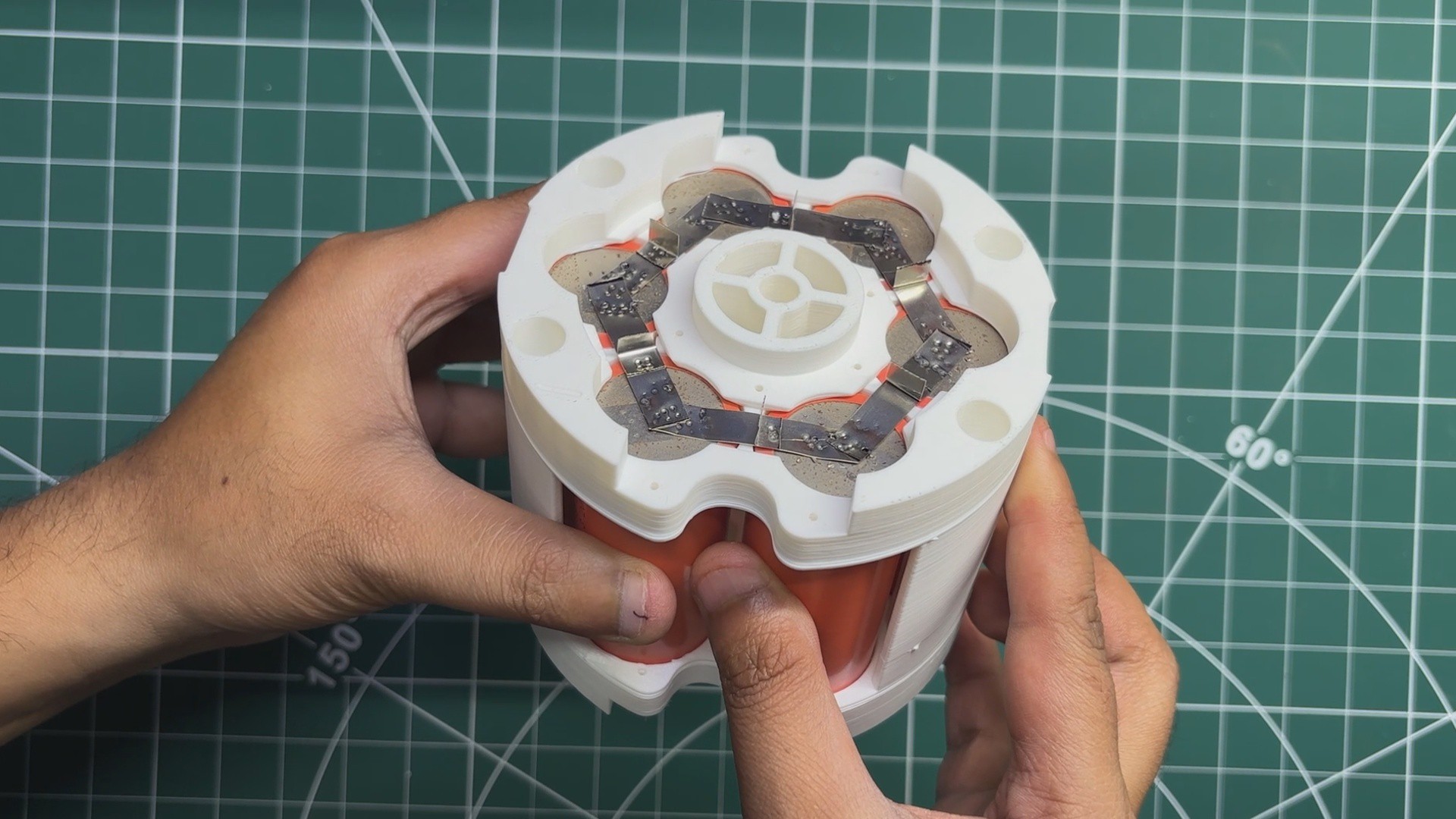
The electrical connections are made next. We begin by placing the custom hexagonal nickel strip on the positive side of the cell holder. Using a spot welder, the nickel strip is welded to the terminals of all six cells, electrically connecting them in parallel.
The same process is then repeated on the negative side of the battery pack using another hexagonal nickel strip.
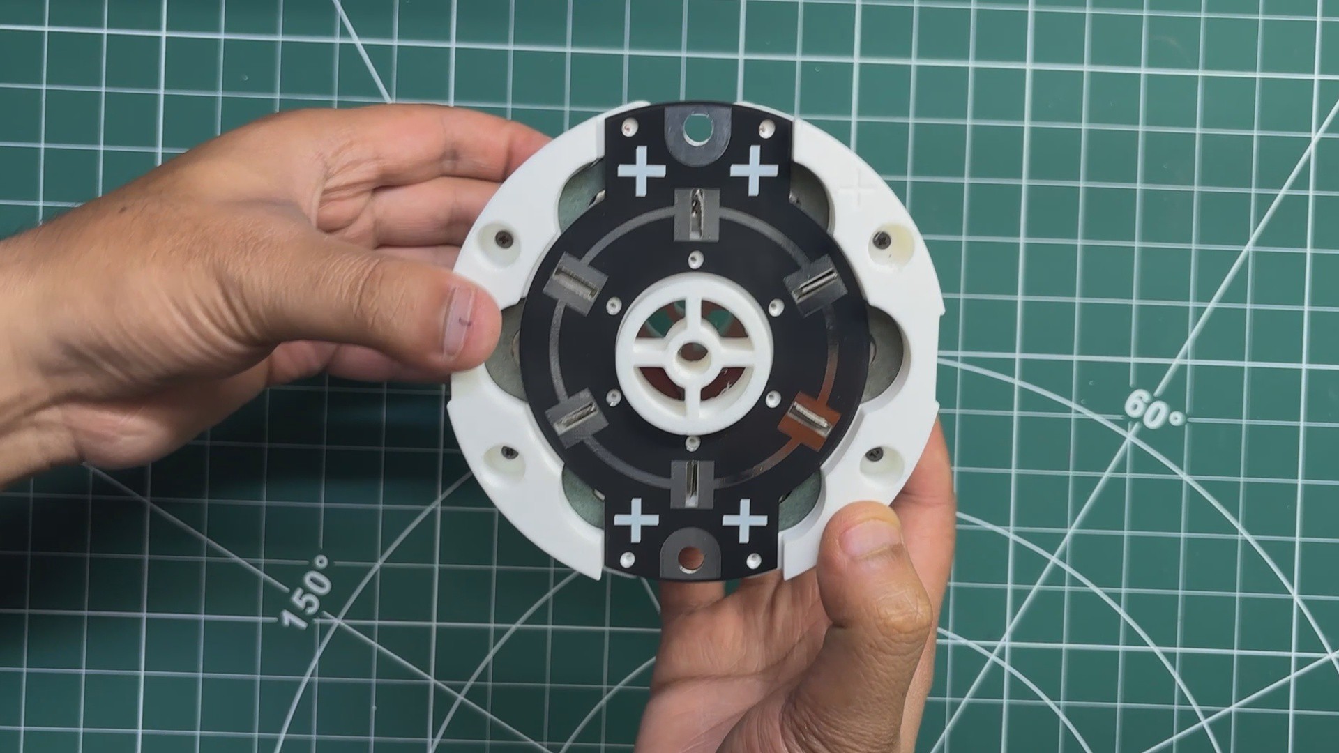
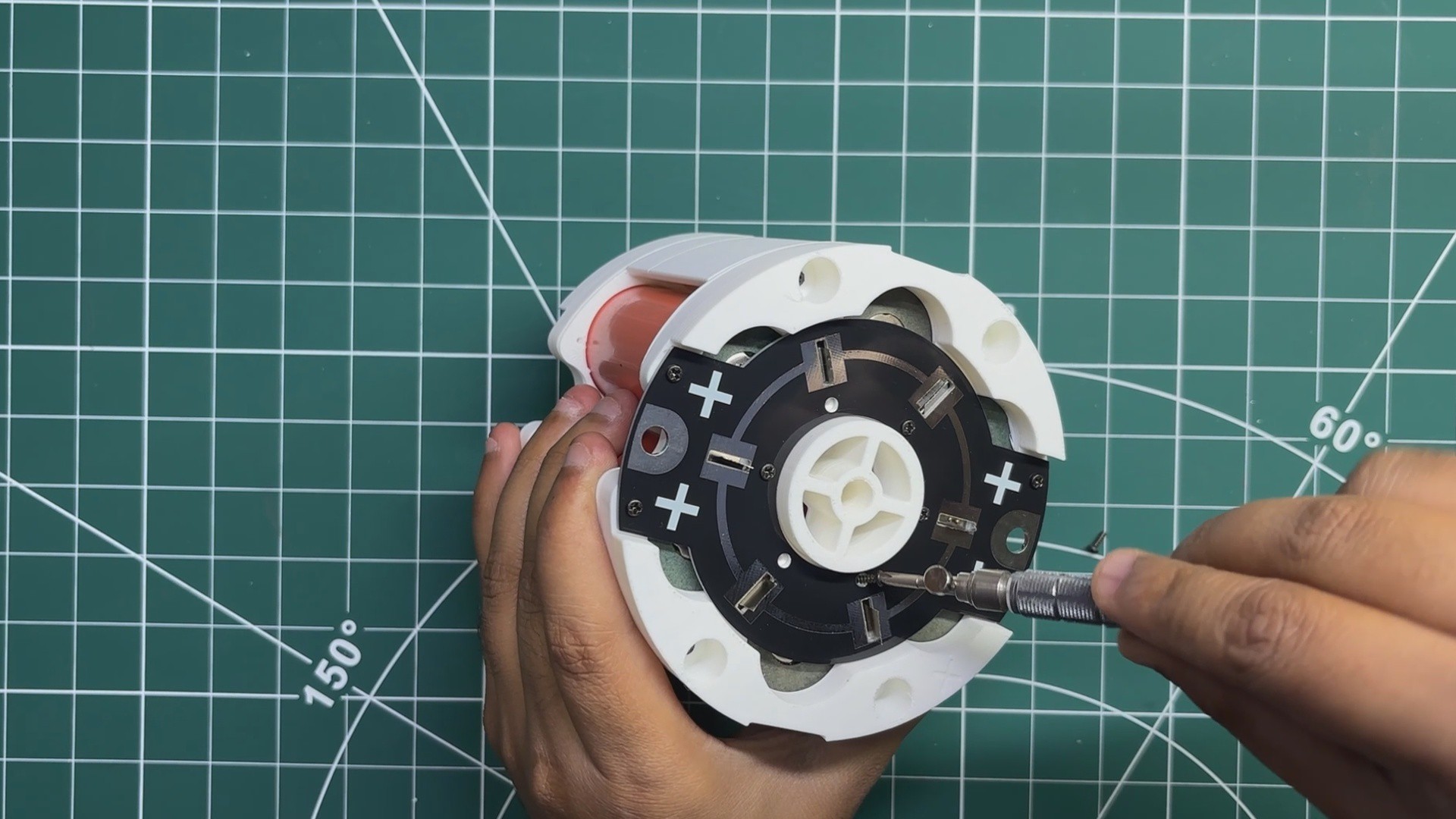
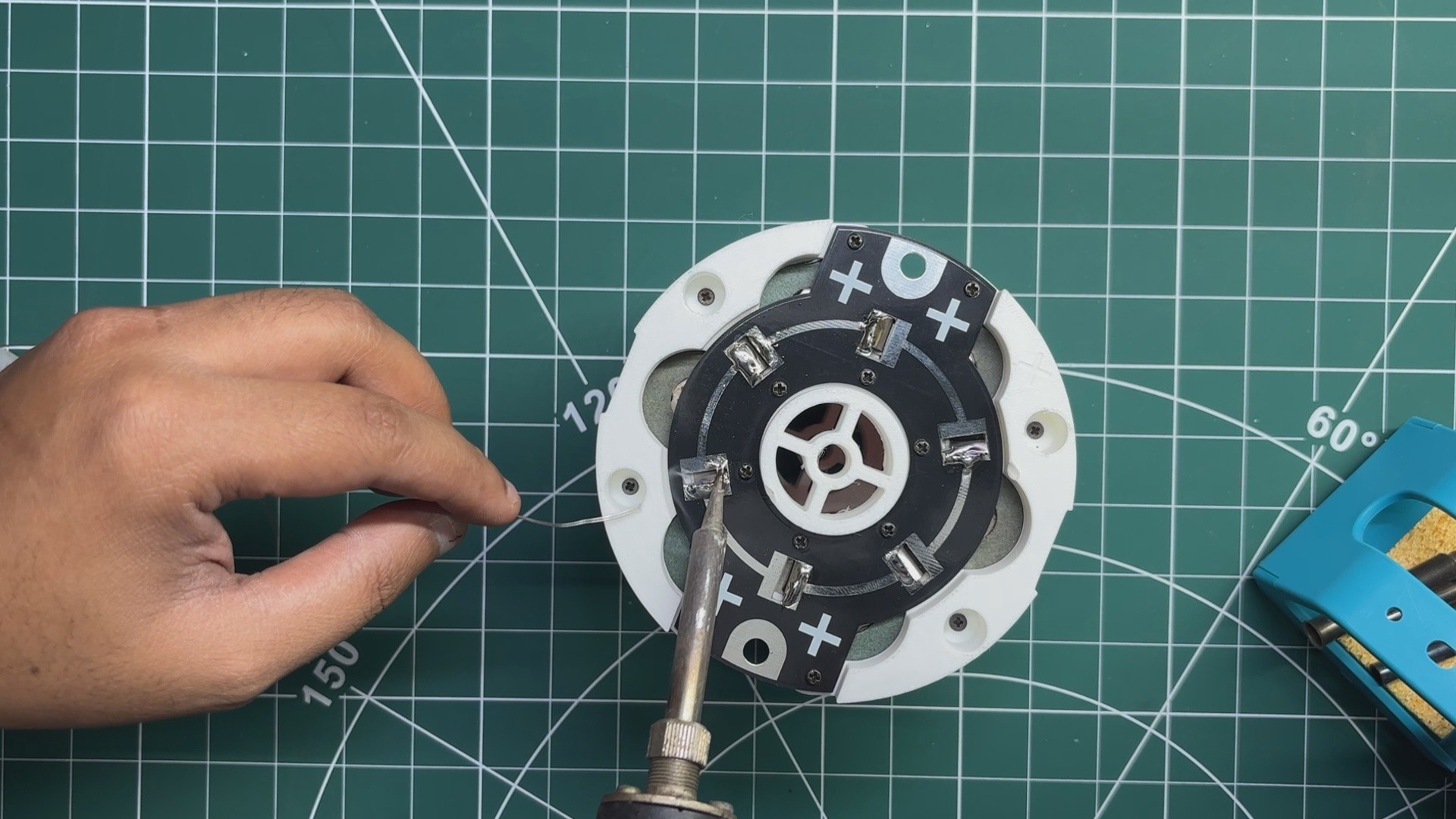
Once both nickel strips are spot-welded, the connection PCBs are placed over the nickel strips and secured using M2 screws. Finally, the nickel strips are soldered to the PCBs, creating a solid electrical connection between the cells and the connection boards.
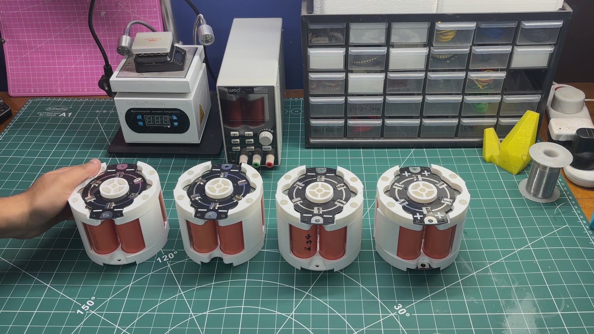
The same process is done on both the positive and negative sides of the cell holder, completing one fully assembled parallel battery module.
3
TEST
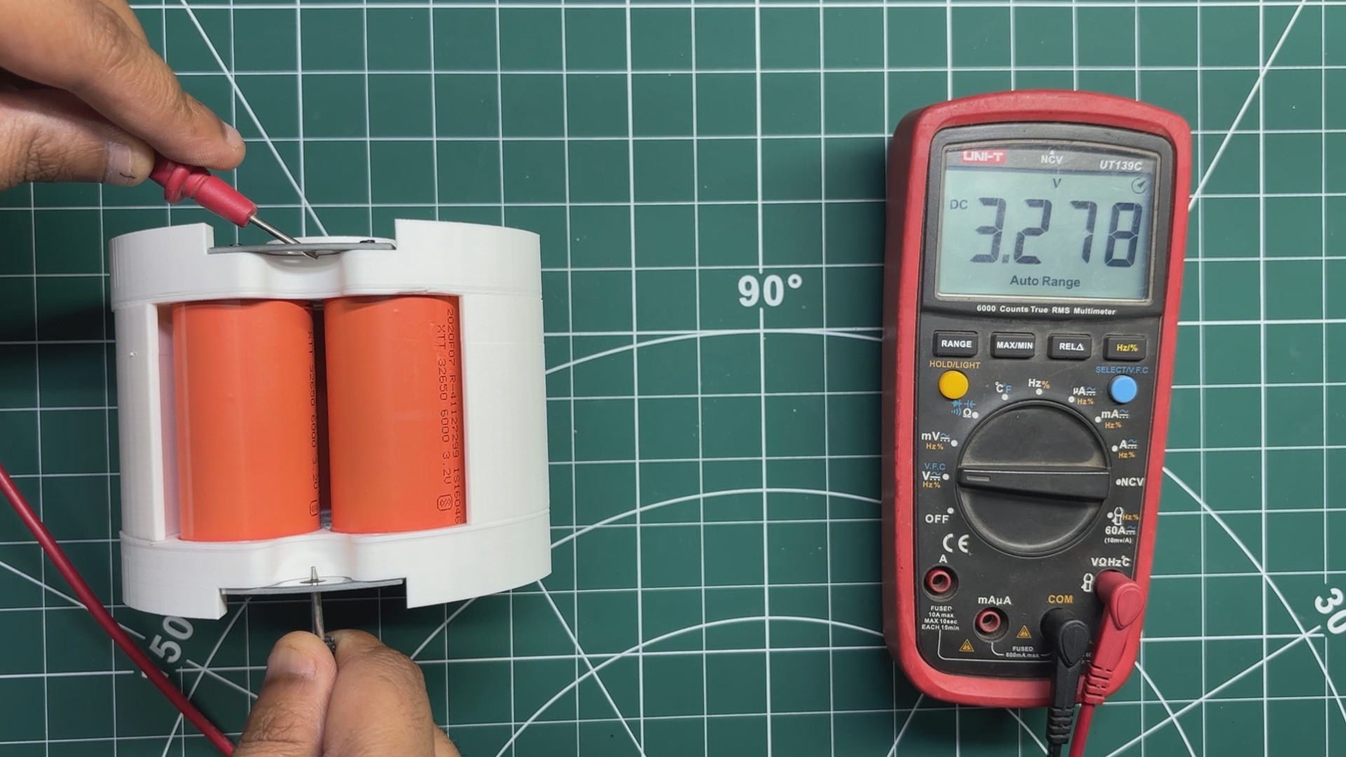
To verify that everything was assembled correctly, I measured the output voltage of the completed parallel cell holder using a multimeter. The measured voltage was approximately 3.27V, confirming that all six cells were properly connected in parallel and the assembly was functioning as expected.
Since the final battery pack requires four identical parallel cell holders, I repeated the entire assembly process three more times until all four modules were complete and ready to be connected in series.
4
COMBINED PACK ASSEMBLY
Now comes the main assembly of the battery pack.
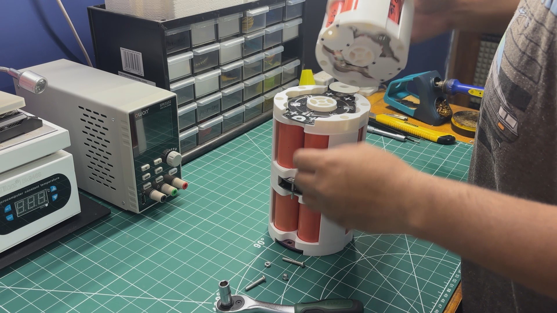
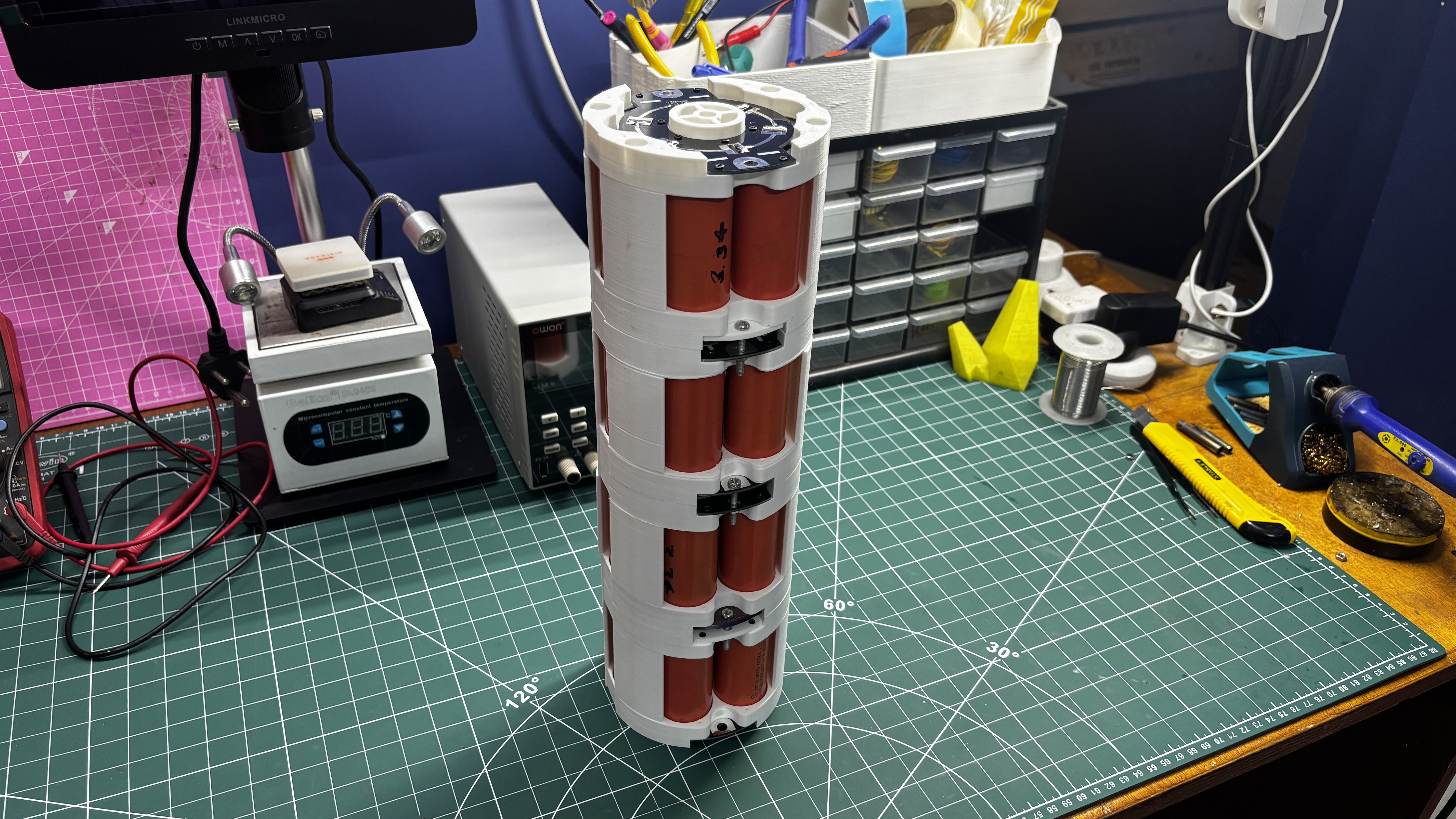
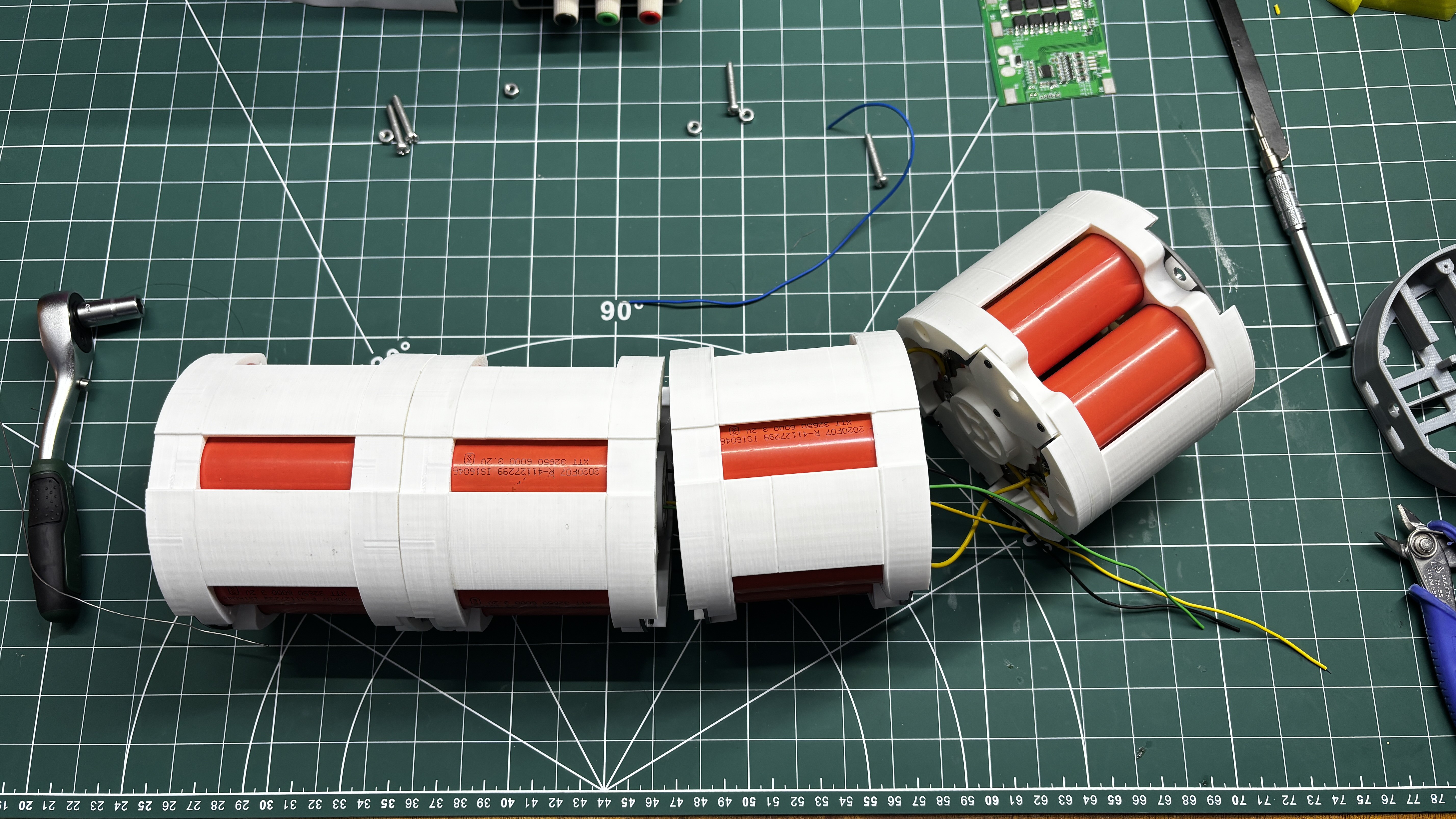
The process begins by stacking all four parallel cell holders on top of one another in the correct orientation, as shown in the assembly diagram.
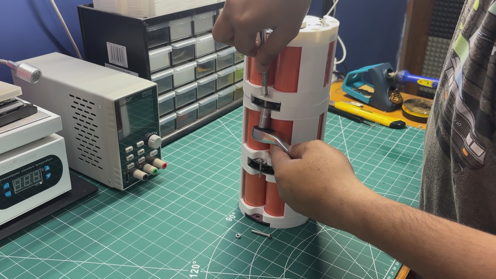
To electrically connect the four modules in series, M4 nuts and bolts are used to fasten the connection PCBs together. These connections link the positive terminal of one parallel pack to the negative terminal of the next, completing the 4-series (4S) configuration.
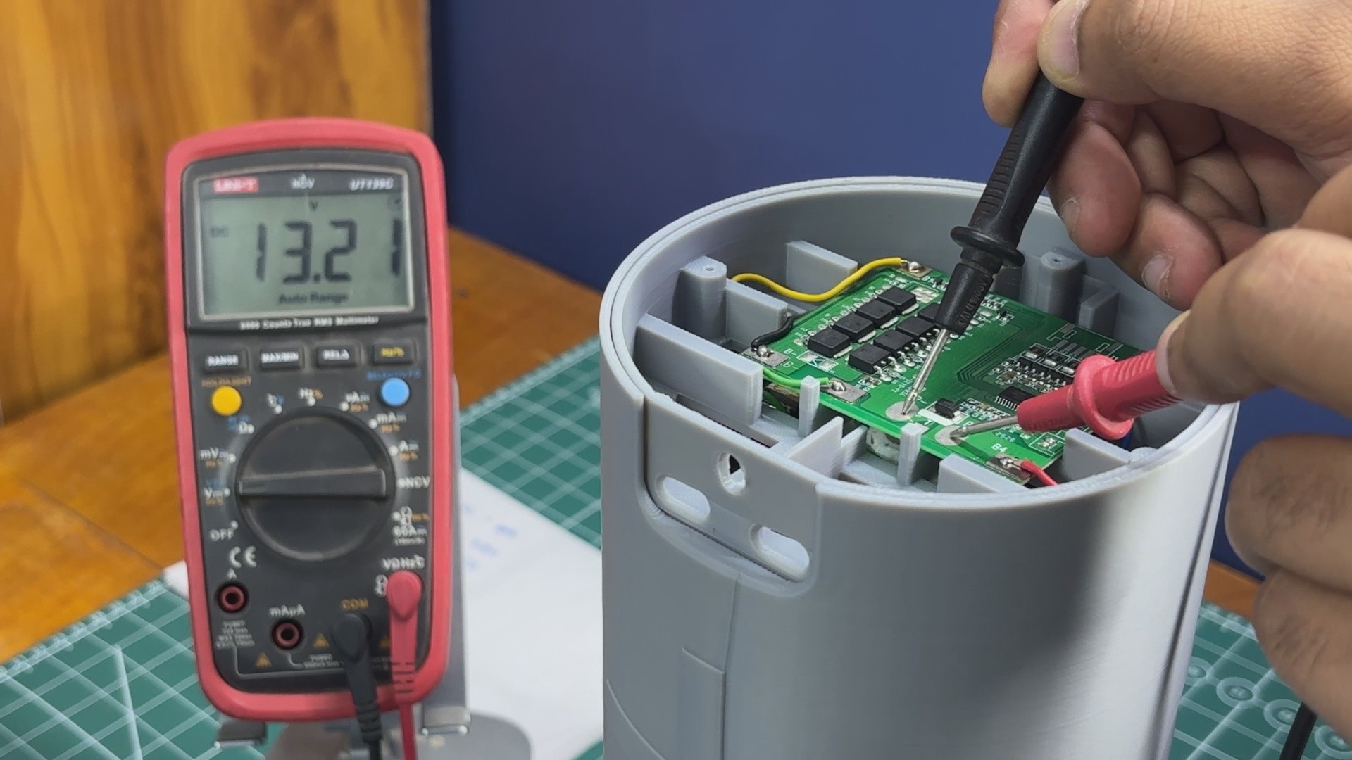
Once all four modules are connected, the battery pack has a nominal output voltage of approximately 13.3V. The positive output terminal is located at the topmost cell holder, while the negative output terminal is located at the bottommost cell holder, making these the main output terminals of the completed battery pack.
5
WIRING
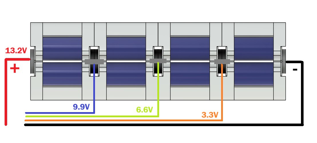
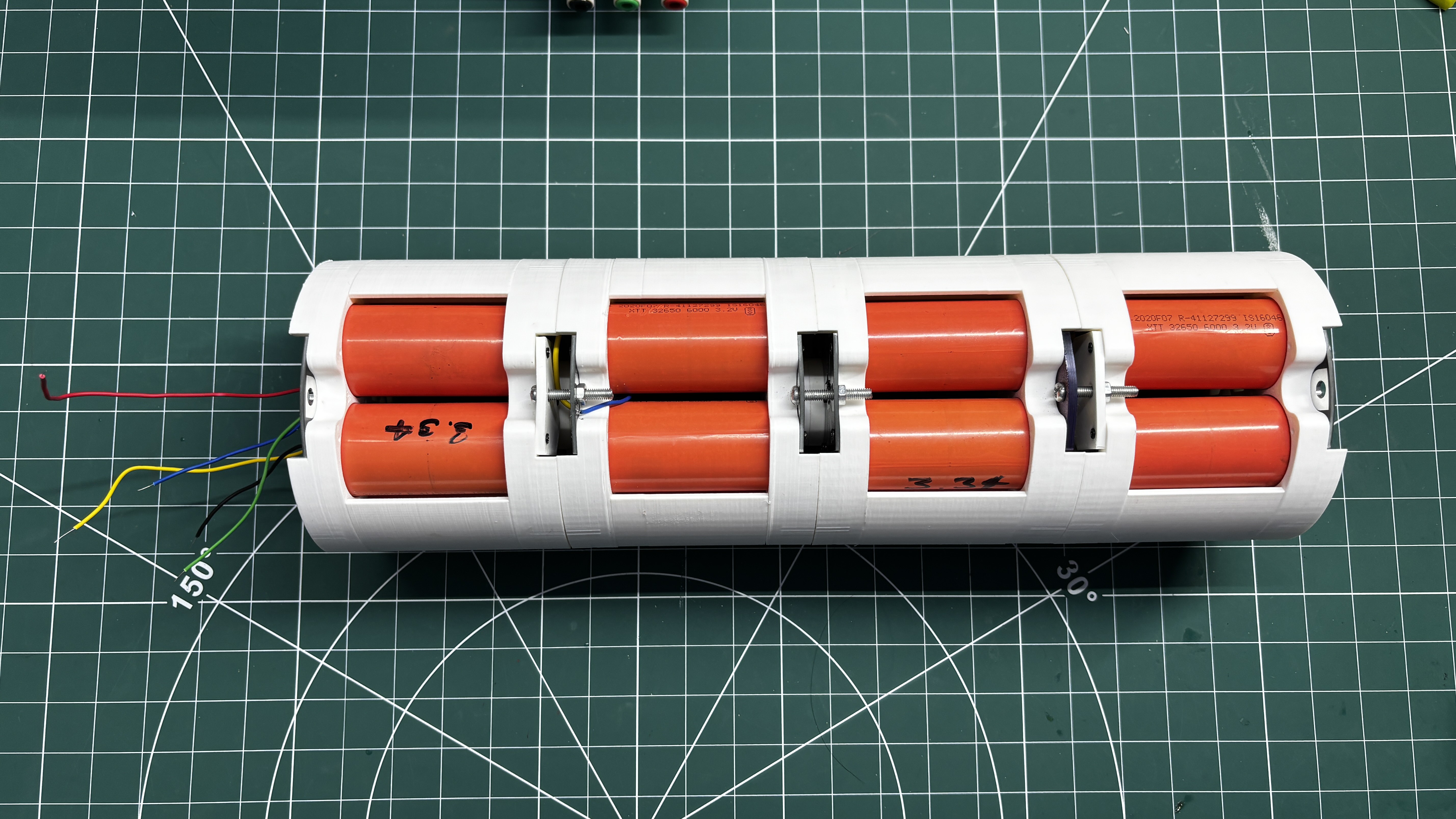
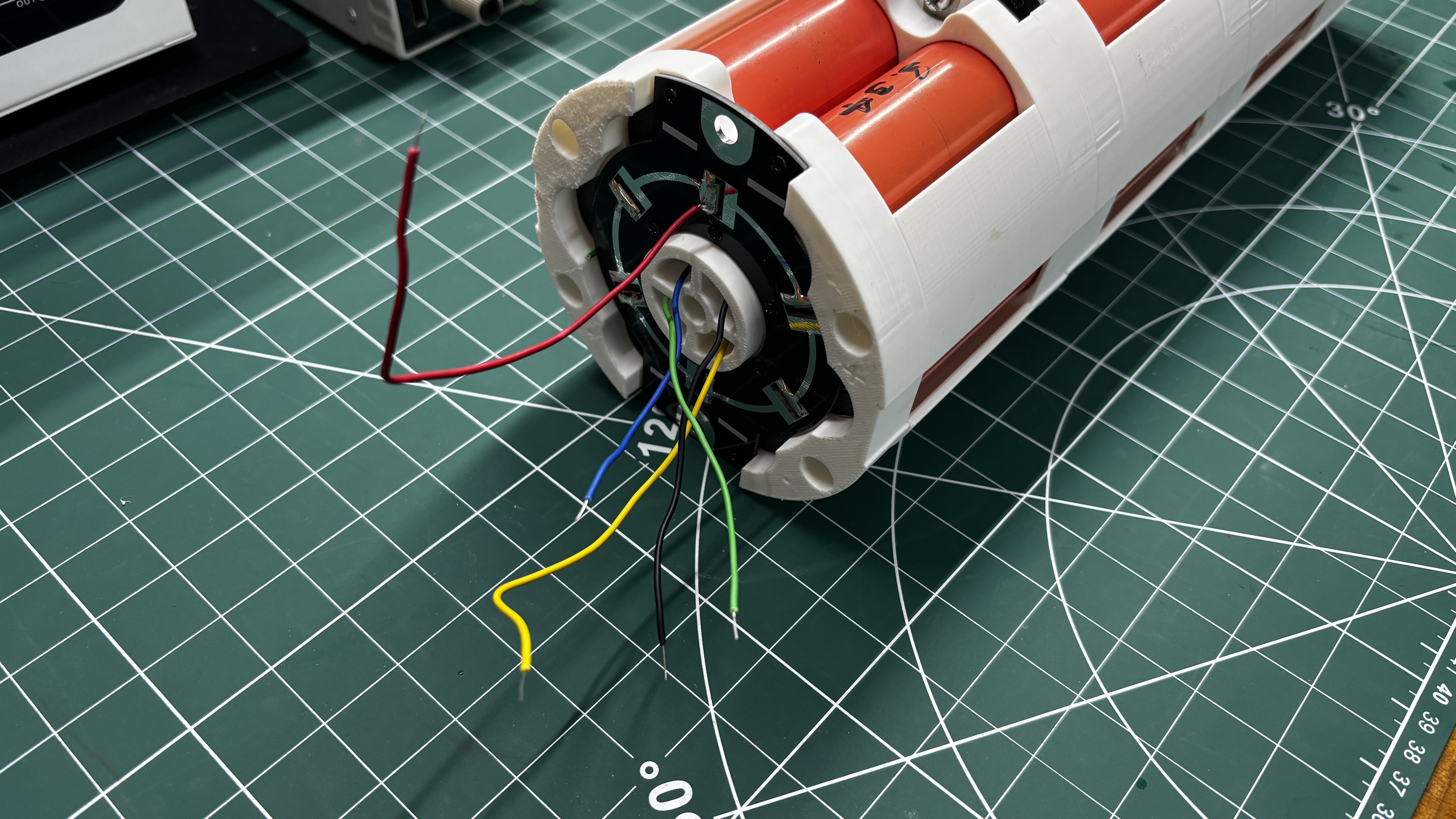
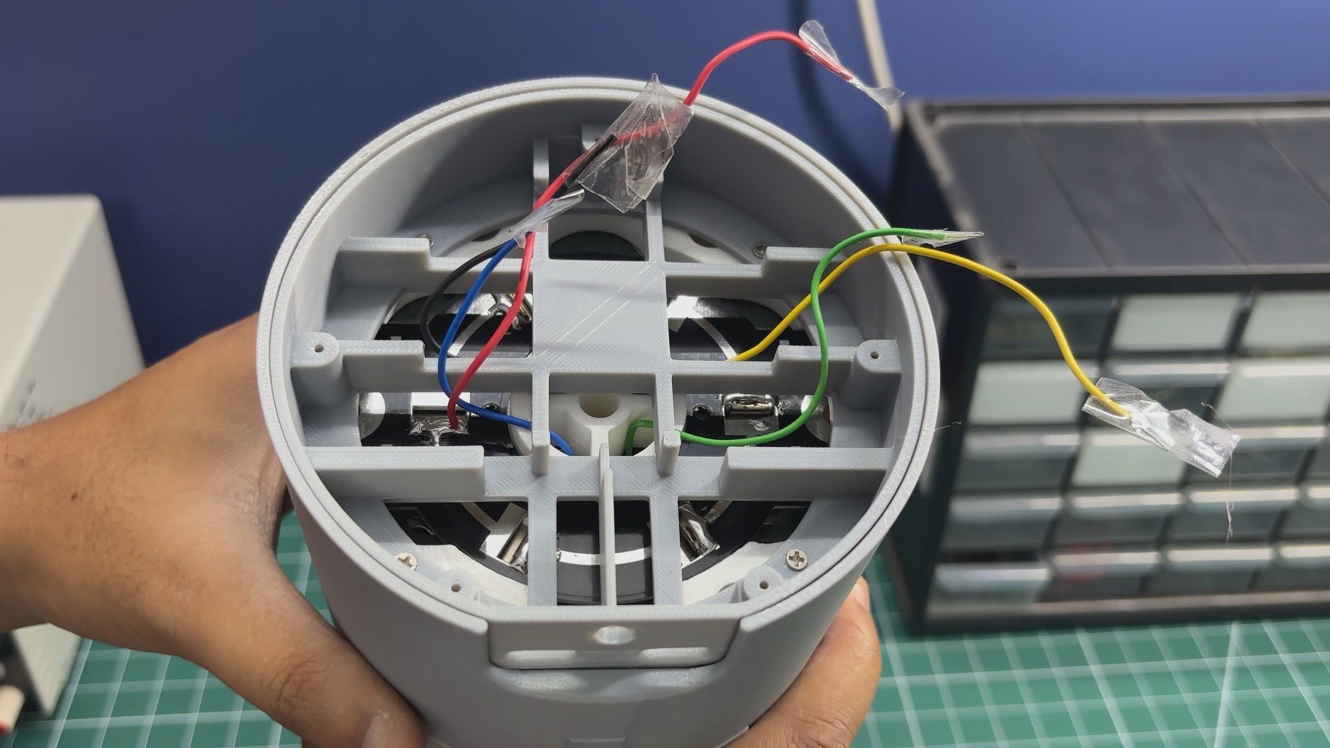
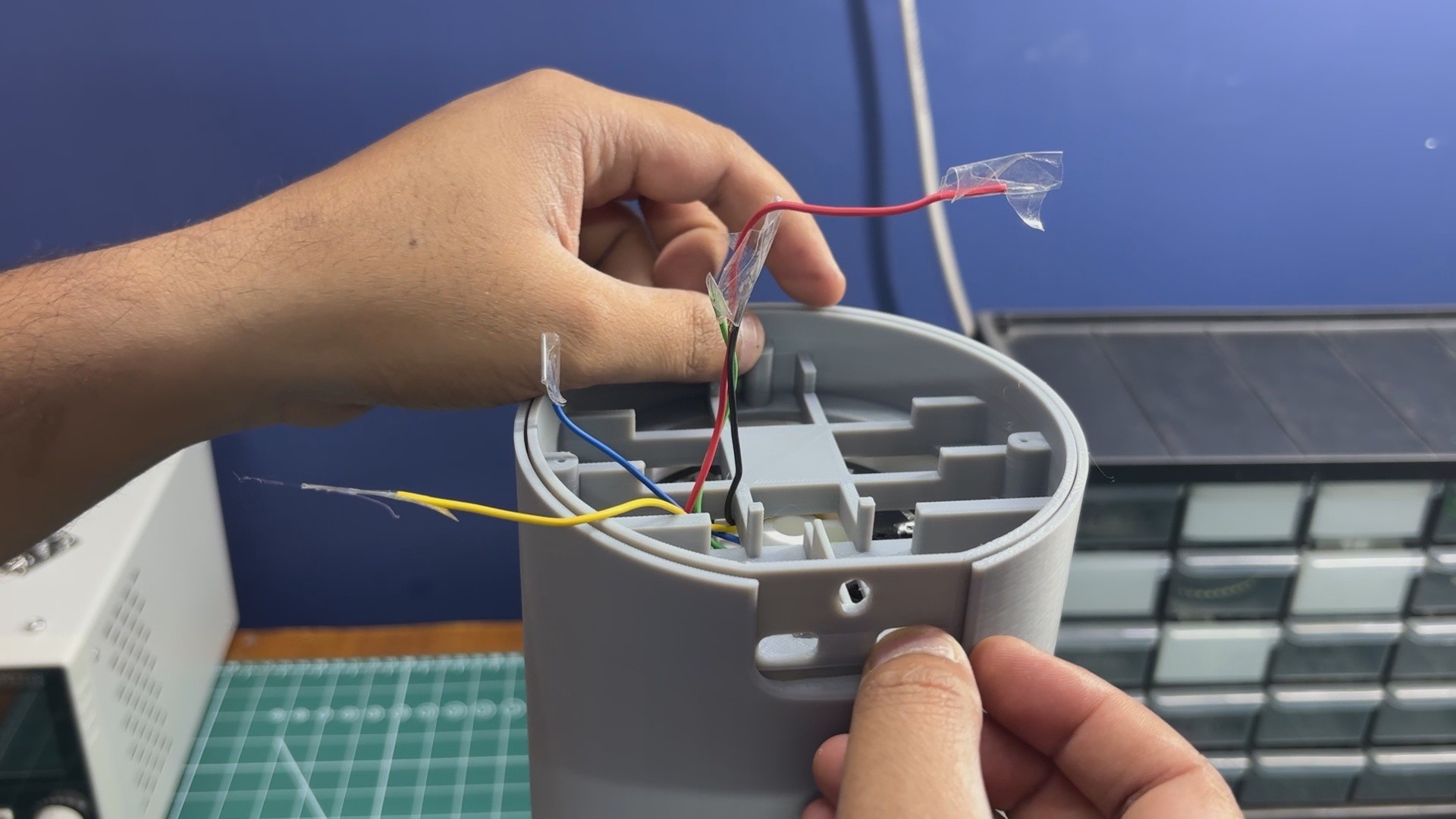
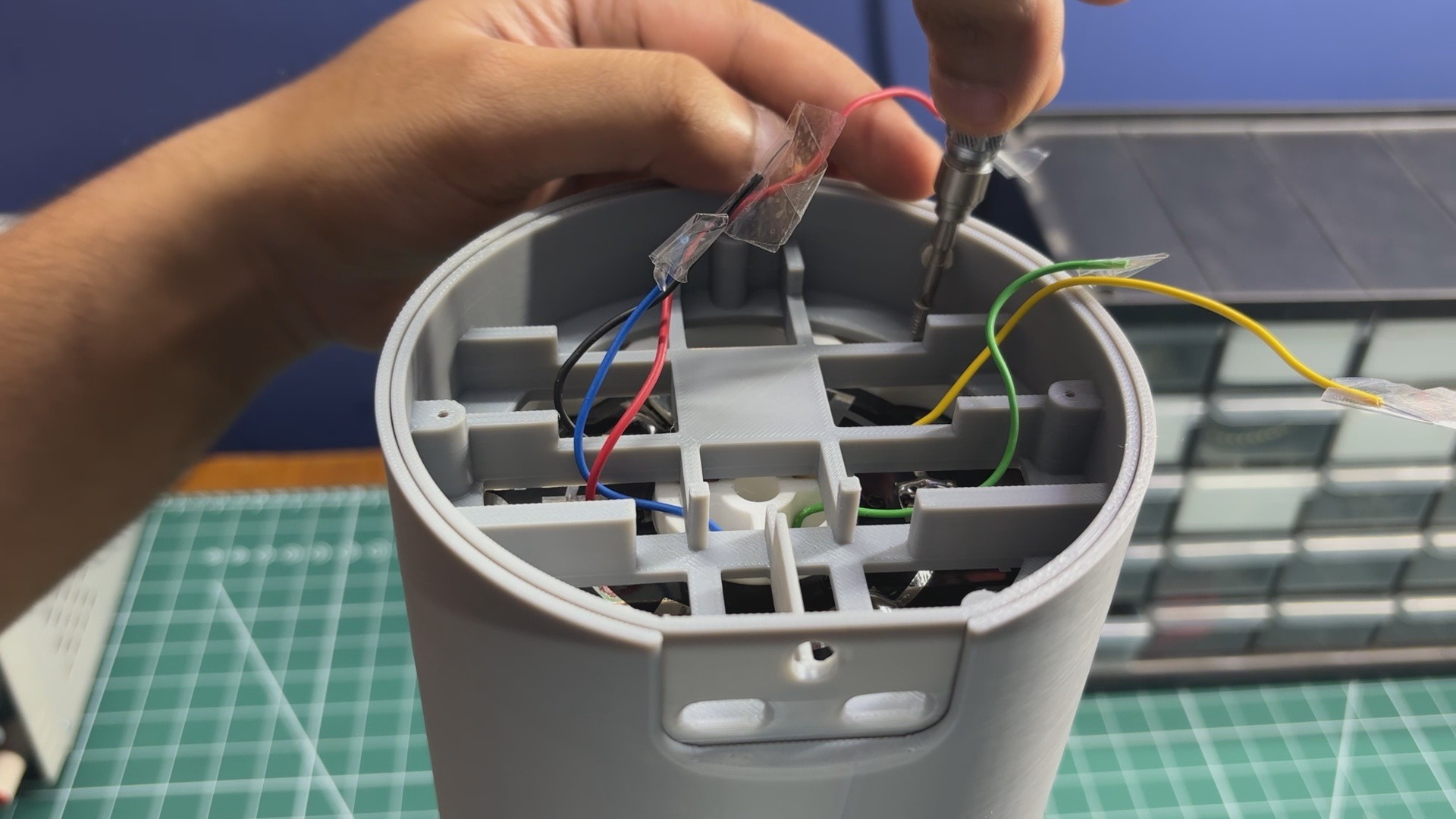
We begin the wiring process by connecting wires to each parallel cell holder according to the provided wiring diagram.
The wires are soldered to the connection PCB of each parallel pack and then routed through the opening in the center of the cell holder. All of the wires are passed through this central opening, where they will later be connected to the BMS.
For the power connections, I am using 16 AWG single-core copper wire, which is capable of handling currents well above the requirements of this project while keeping voltage drop and heat generation to a minimum. Using thicker wire also makes the battery pack more reliable when powering higher-current loads.
6
TOP LID ASSEMBLY
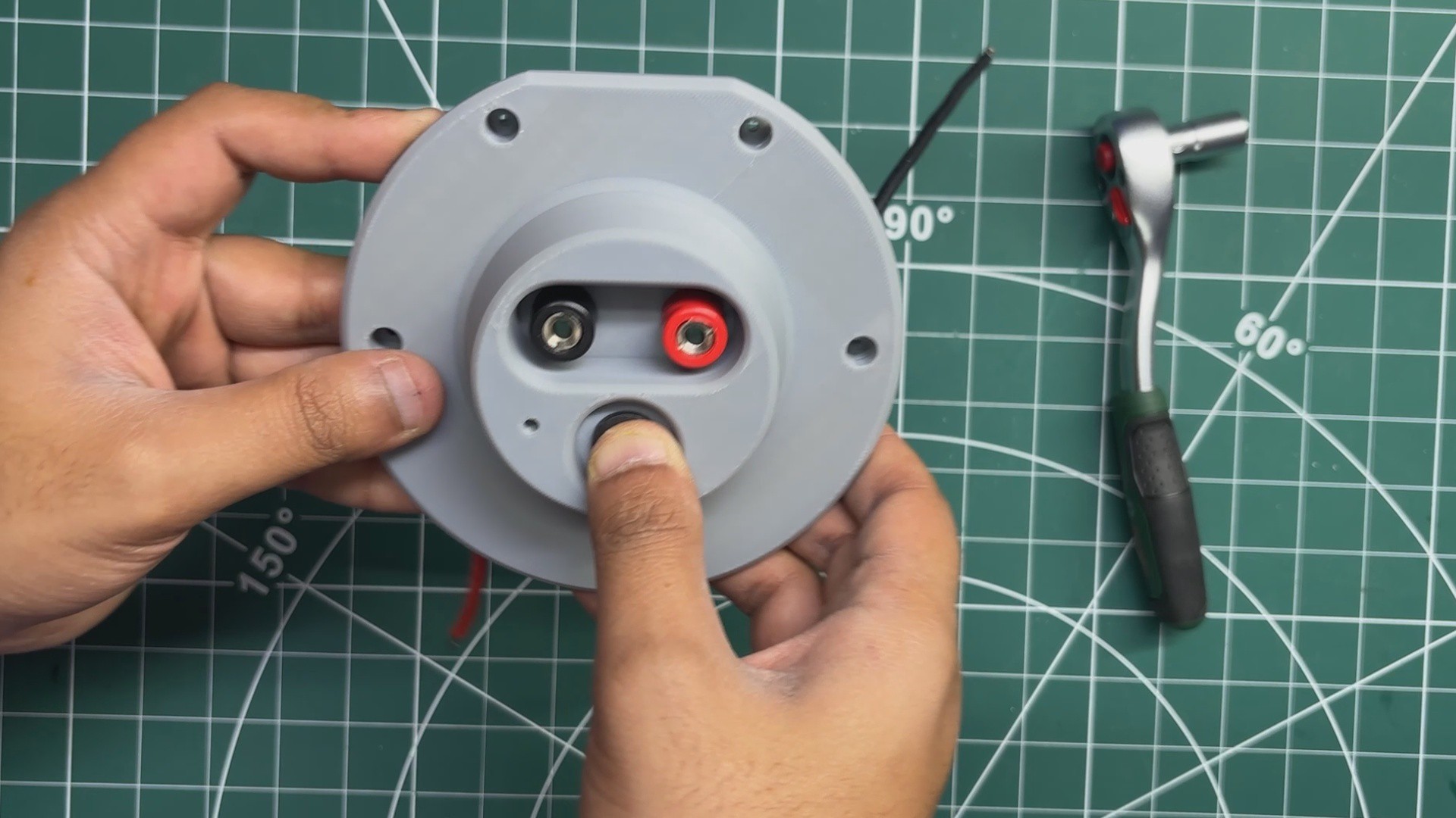
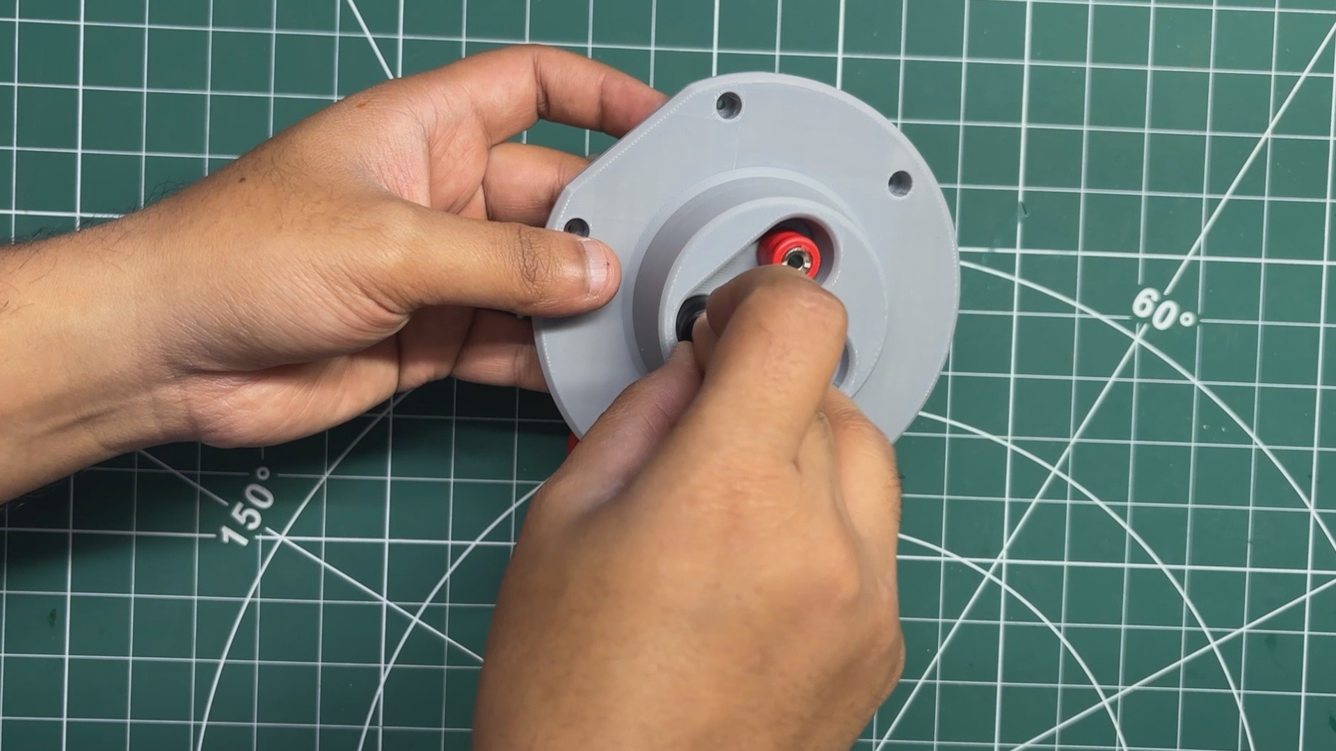
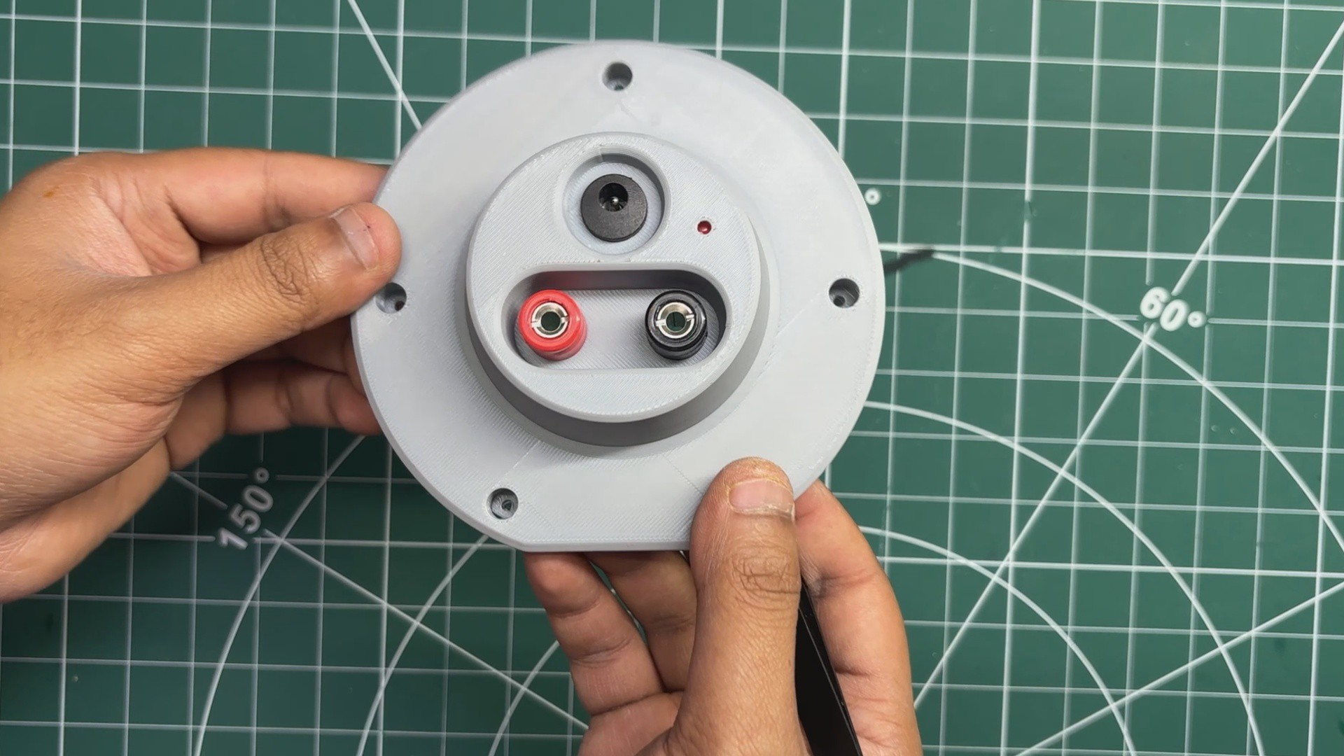
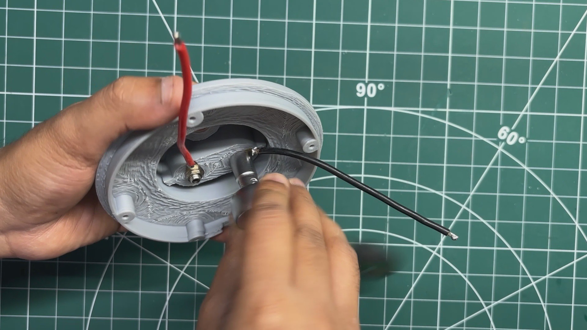
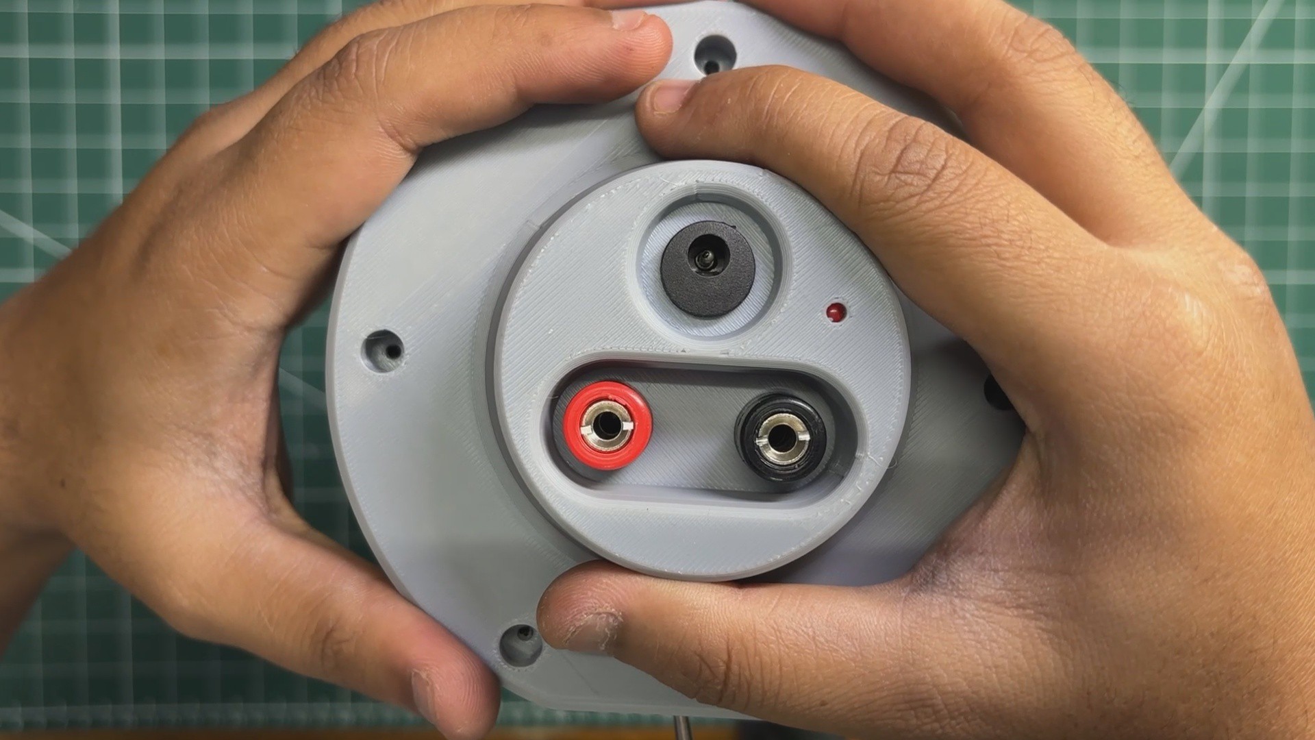
The assembly of the top cover begins by installing the red and black banana connectors into their respective mounting holes. Both connectors are inserted from the outside of the top cover and positioned correctly.
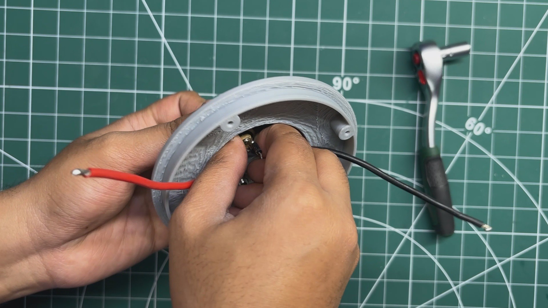
Next, a red and a black wire are soldered to the solder lugs of the banana connectors. The wires are then routed through the openings inside the top cover, and the supplied mounting nuts are tightened to securely lock both banana connectors in place.
The DC barrel jack is installed next and secured using its supplied mounting nut.
For the wiring, the VCC terminal of the DC barrel jack is connected to the cathode of an SR206 Schottky diode, while the anode of the diode is connected to the red banana connector. The GND terminal of the DC barrel jack is connected directly to the black banana connector.
Next, a 3mm LED is installed in its mounting hole. The anode of the LED is connected to the VCC terminal of the DC barrel jack before the diode. This ensures that the LED only illuminates when a charger is plugged into the DC jack.
Finally, a 10kΩ resistor is soldered between the cathode of the LED and the GND terminal of the DC barrel jack, completing the charging indicator circuit.
7
OUTER SHELL ASSEMBLY
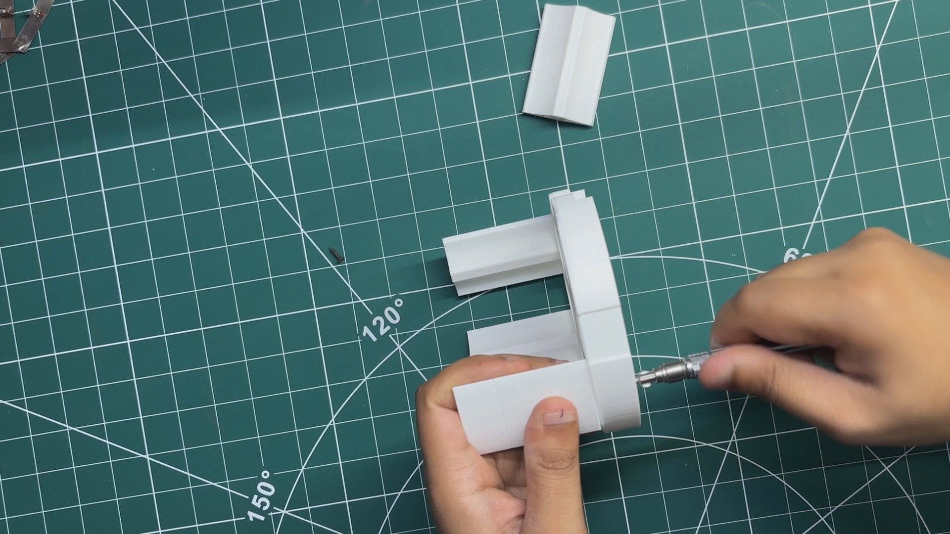
We begin the outer shell assembly by placing the base onto the bottom of the battery pack and securing it using four M2 screws.
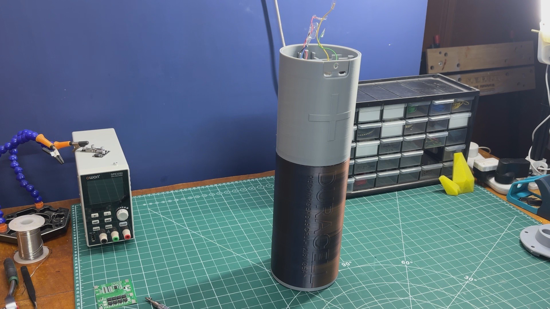
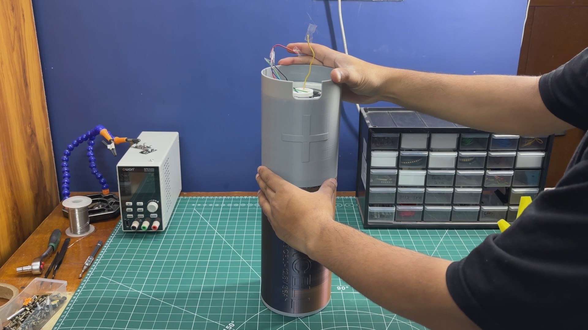
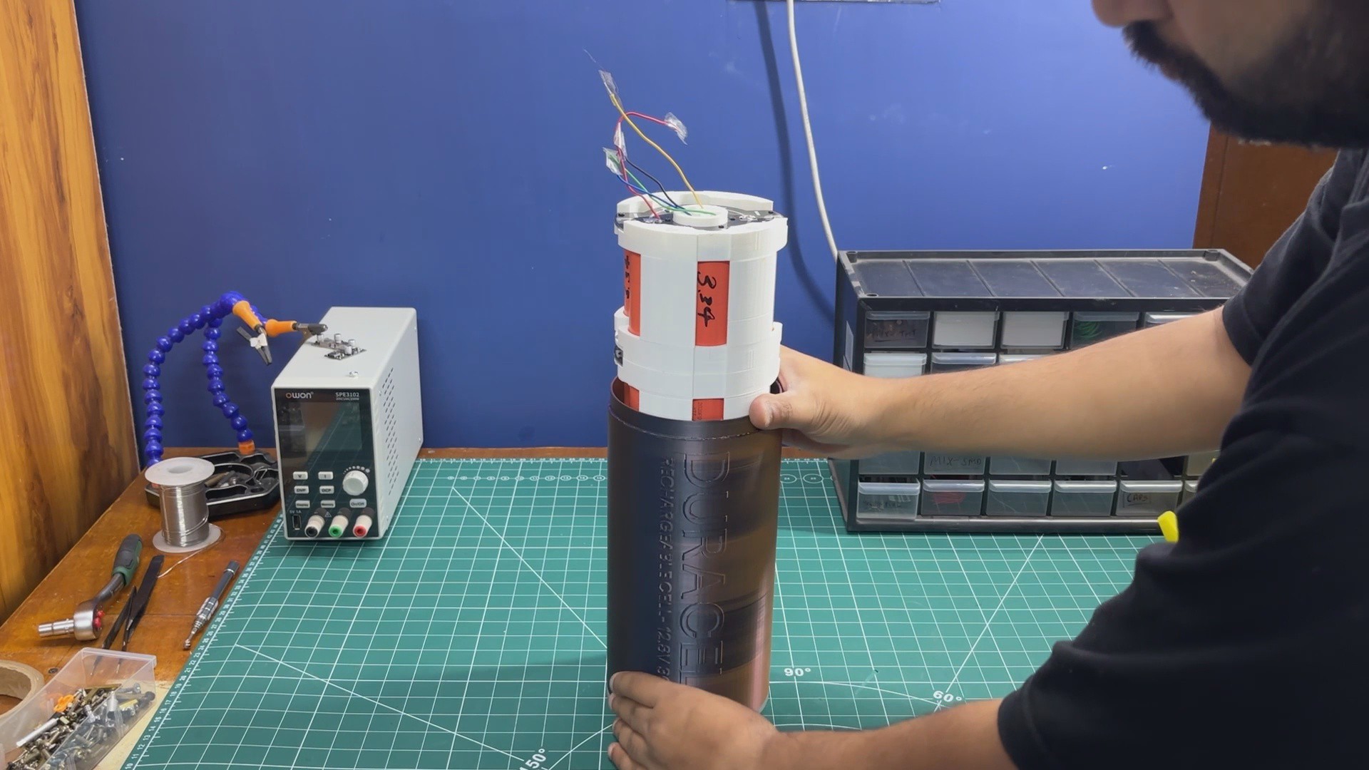
The battery pack is then turned over, and the Duracell shell is slid into position over the cylindrical battery pack. Once the Duracell shell is in place, the upper shell is also slid into its designated position.
Next, the inner support is installed at the top of the battery pack and secured using M2 screws. This inner support not only provides a mounting point for the electronics but also locks the upper shell and Duracell shell in place, keeping the entire outer enclosure securely assembled.
8
FINAL ASSEMBLY
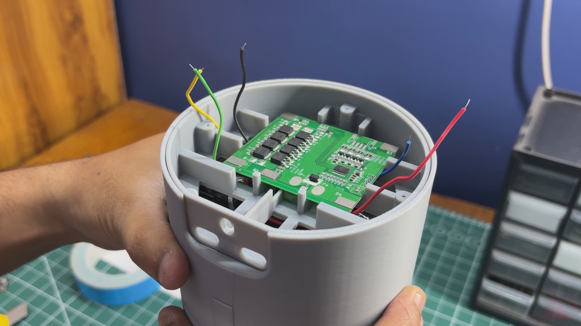
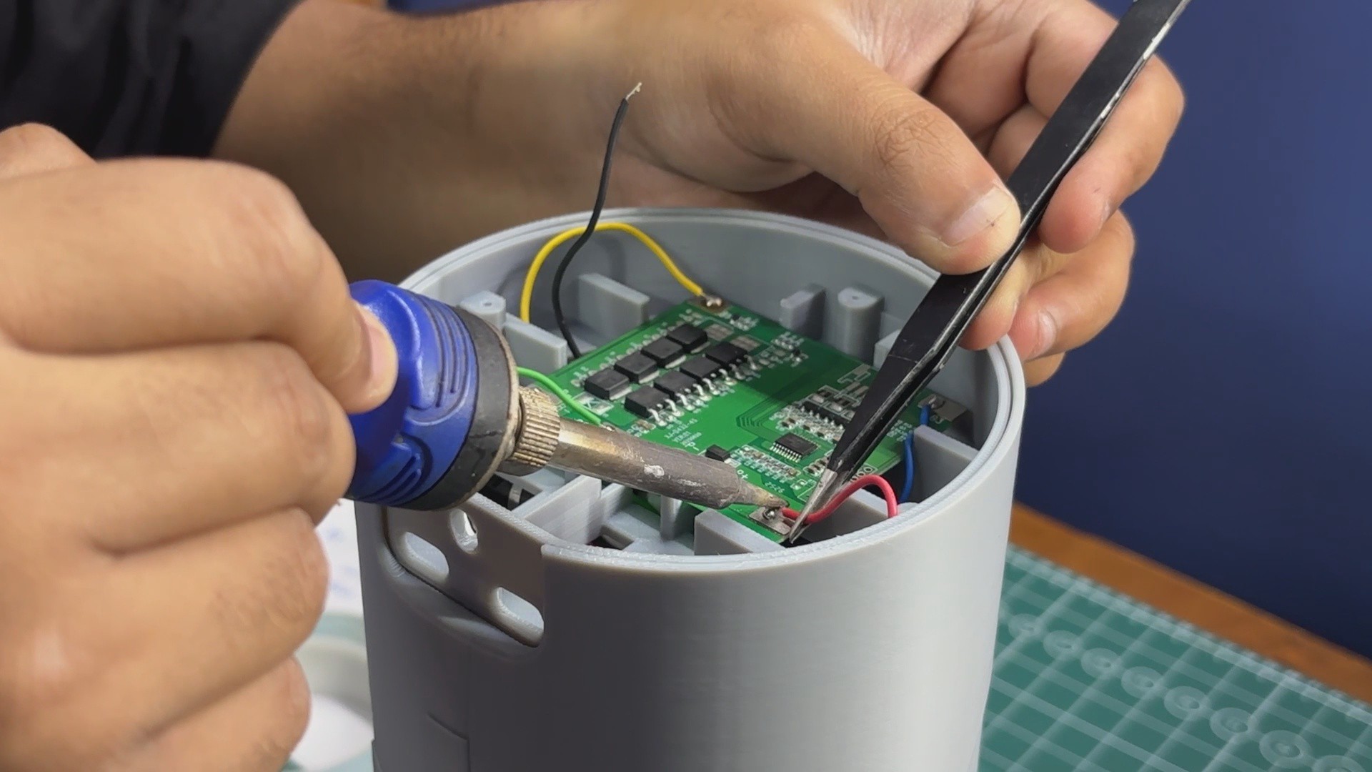
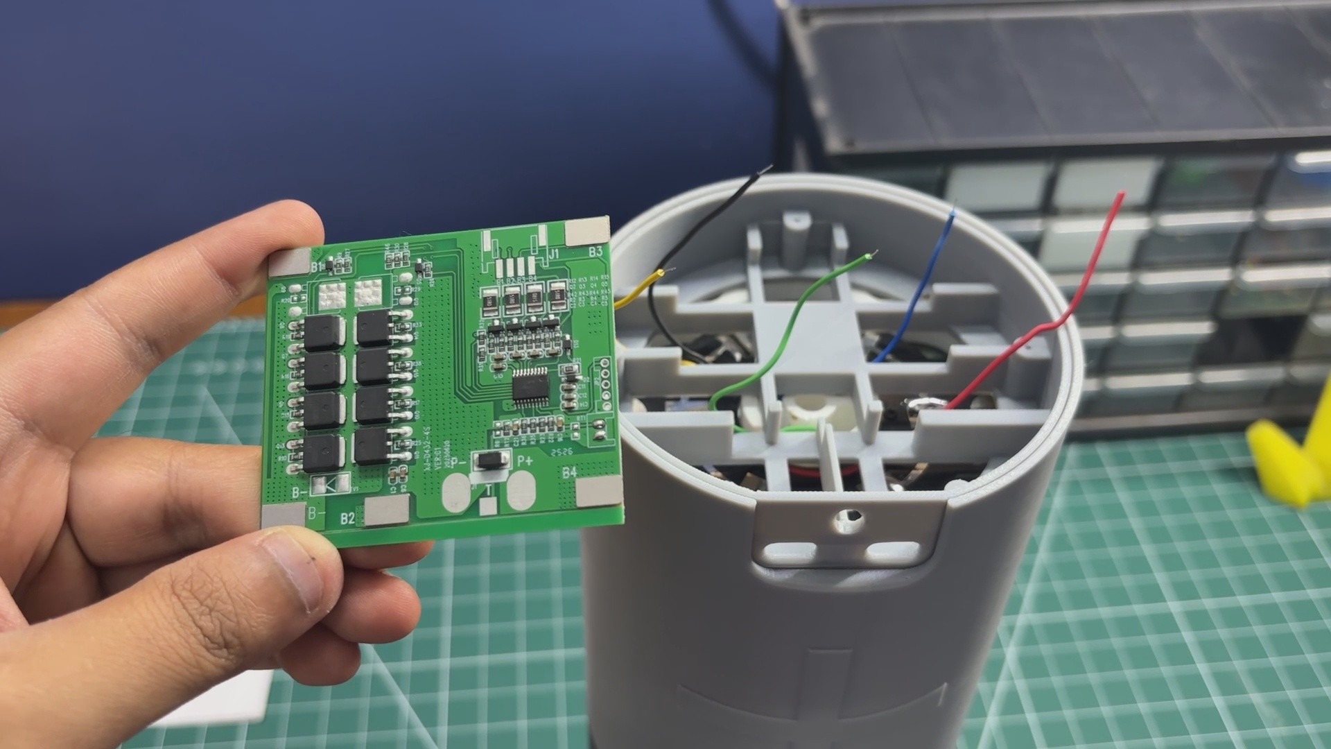
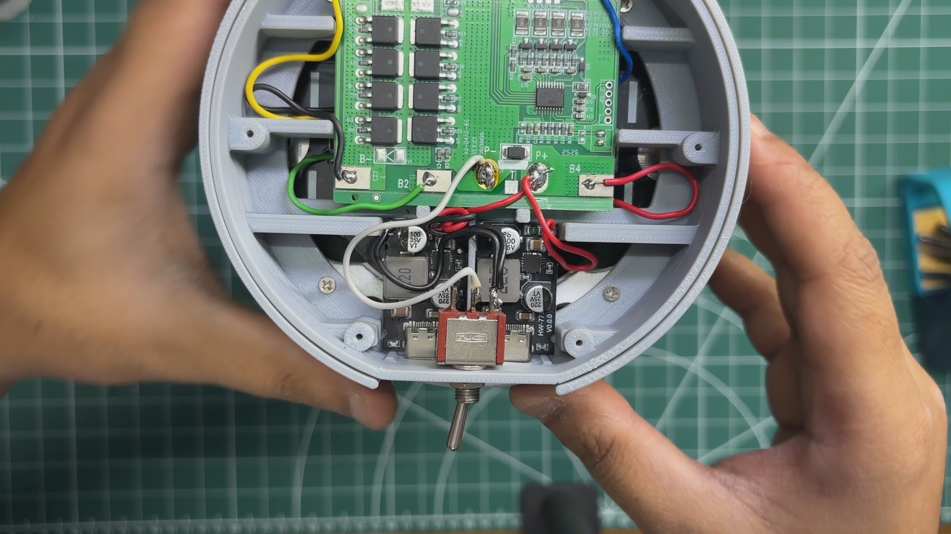
We begin the final assembly process by mounting the BMS inside the inner support part. To secure it in place, I applied a piece of double-sided thermal tape and then placed the BMS on top. The thermal tape keeps the BMS firmly attached while also helping transfer heat to the mounting surface.
Next, by following the wiring diagram, the BMS is connected to the battery pack. The B- terminal is connected to the battery negative, B1 to the 3.3V tap, B2 to the 6.6V tap, B3 to the 9.9V tap, and B+ to the 13.2V positive terminal of the battery pack.
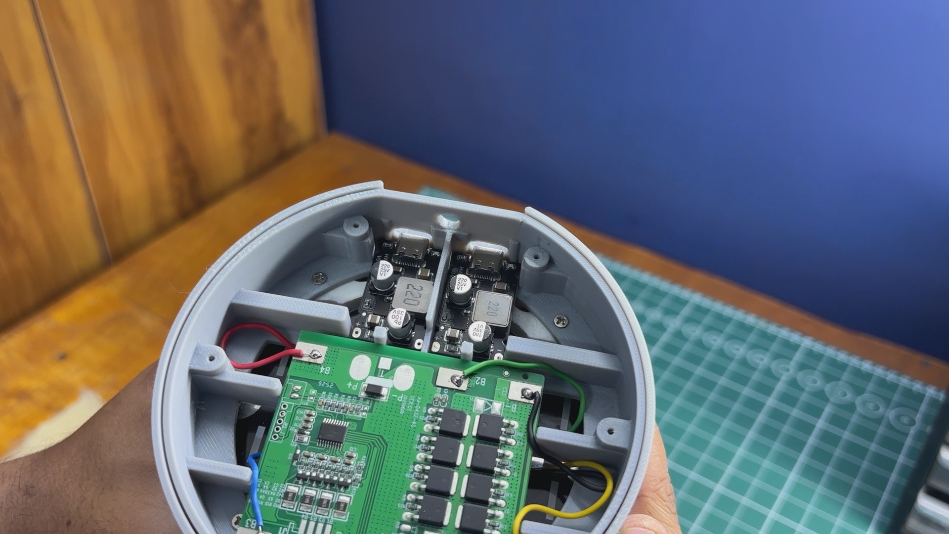
The two 65W USB-C PD modules are then installed. Thermal tape is applied beneath each module before placing it into its respective position.
After that, the lever switch is installed just above the PD modules and secured using the supplied mounting nut.
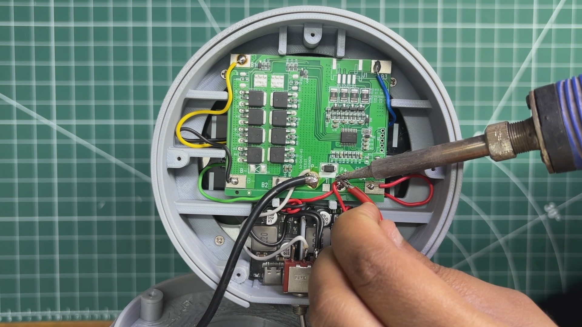
The wiring of the PD modules is fairly straightforward. First, the VIN and GND terminals of both PD modules are connected in parallel. The combined VIN connection is then connected to the P+ terminal of the BMS.
For the negative connection, the combined GND terminals of both PD modules are connected to the COM terminal of the lever switch, while the NC terminal of the switch is connected to the P- terminal of the BMS. In other words, the switch is placed in series with the negative supply line, allowing it to connect or disconnect power to both PD modules simultaneously.
Finally, the pre-assembled top cover is connected to the battery pack by soldering the red wire from the banana connector to the P+ terminal of the BMS and the black wire to the P- terminal.
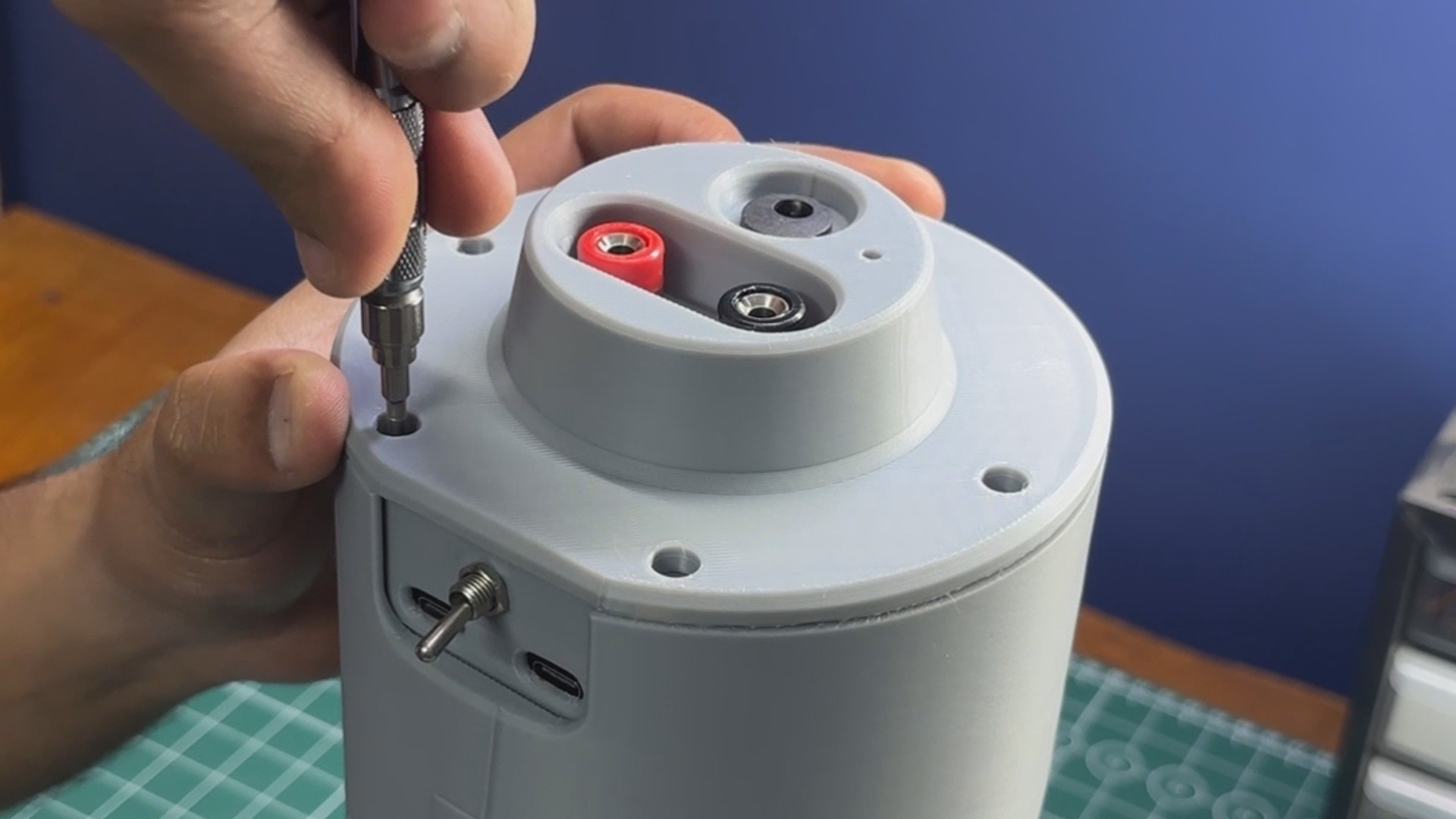
With all the wiring complete, the top cover is positioned onto the enclosure and secured using five M2.5 screws. This locks the entire assembly together and completes the final assembly of the giant Duracell battery pack.
9
RESULT
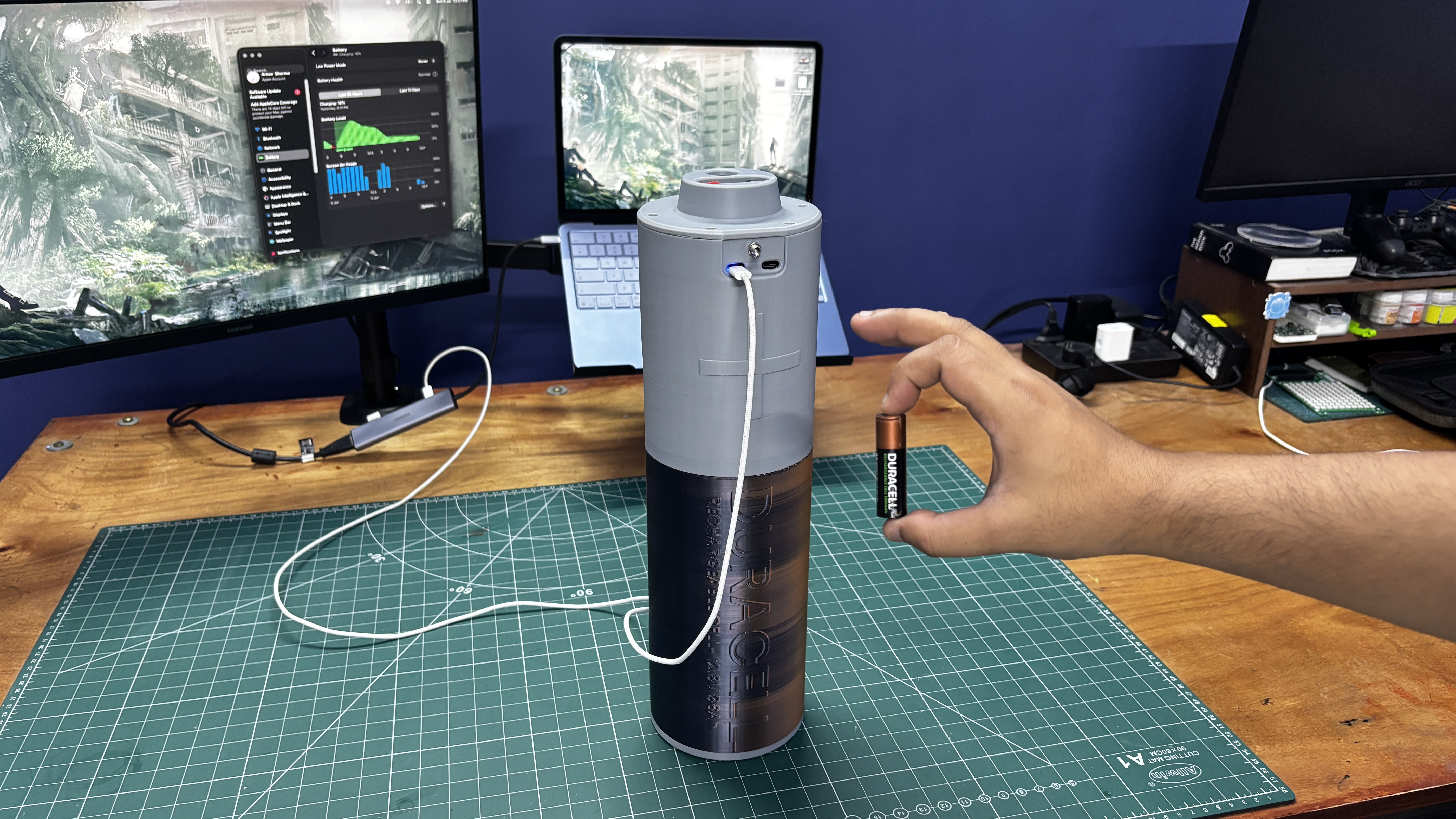
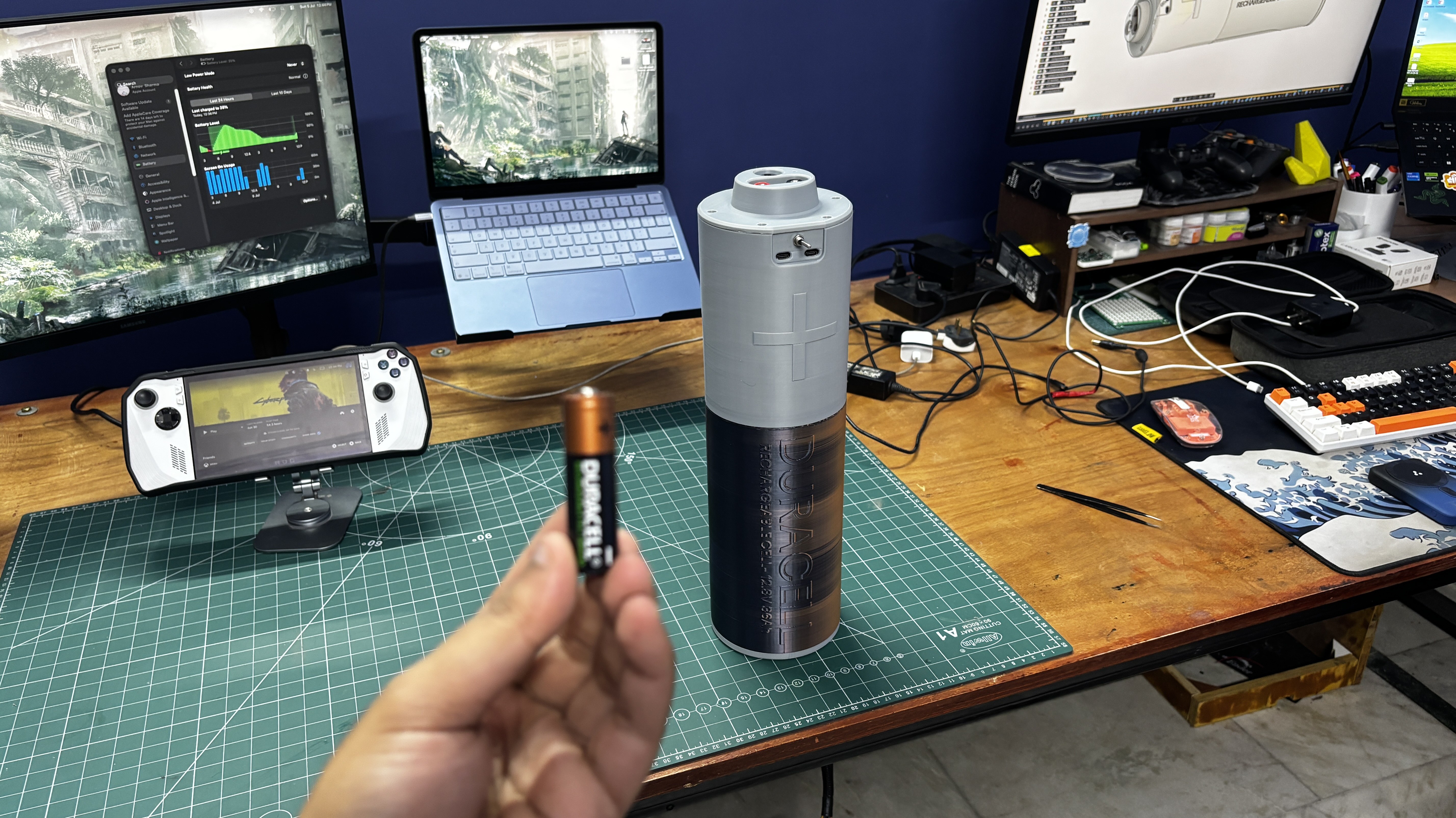
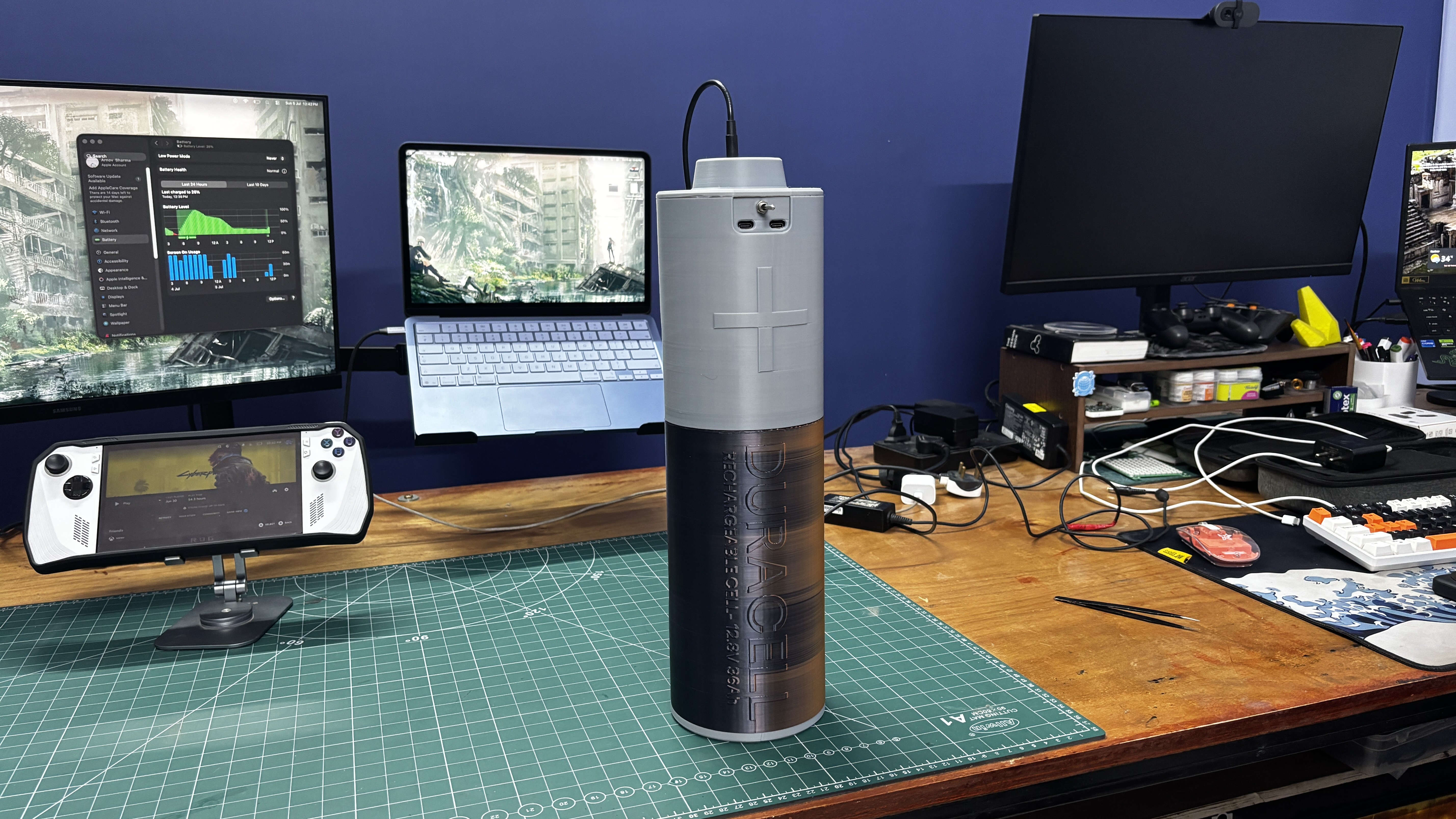
And here's the final result of this giga build—a Duracell battery that is definitely not AA-sized!
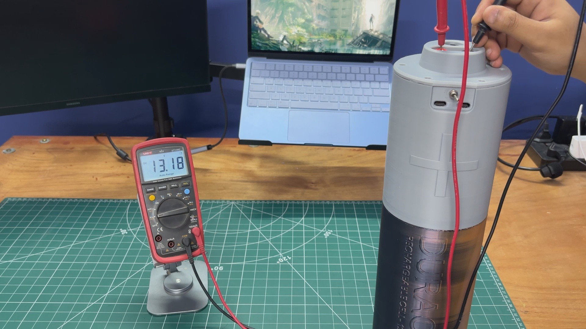
The completed battery pack weighs around 4.7kg and provides a stable 13.2V output, making it suitable for powering a wide range of 12V devices and DIY electronics projects.
Thanks to the onboard dual 65W USB-C PD modules, it can also be used as a portable power bank for charging PD-compatible devices such as smartphones, tablets, handheld gaming consoles, and even laptops.
10
WORKING DEMO
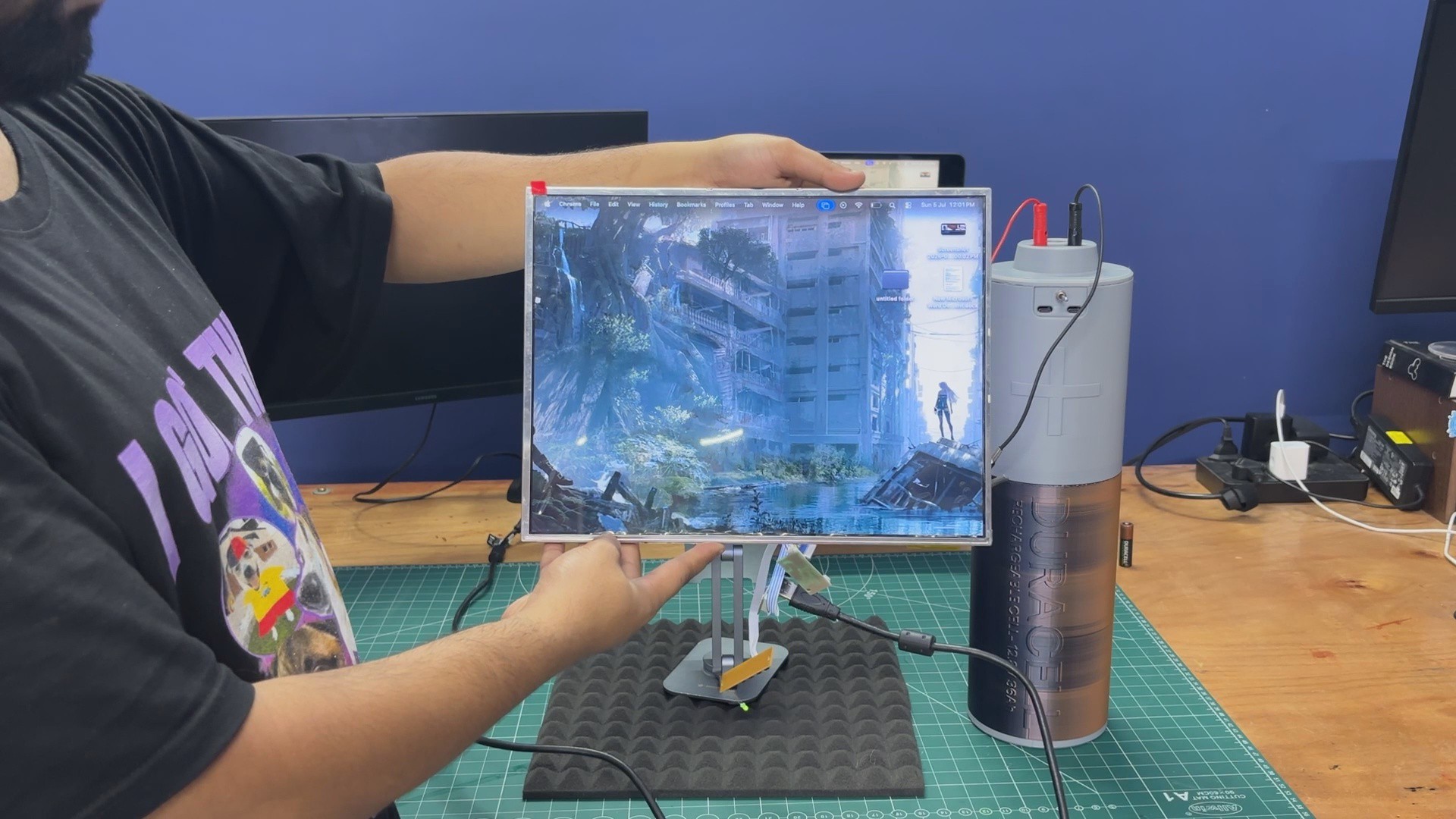
To test the battery pack in the real world, I first connected a 12V monitor that I had previously disassembled for an upcoming project. Using a pair of banana cables, I connected the monitor's driver board to the battery pack's output terminals, and the display powered on and worked perfectly.
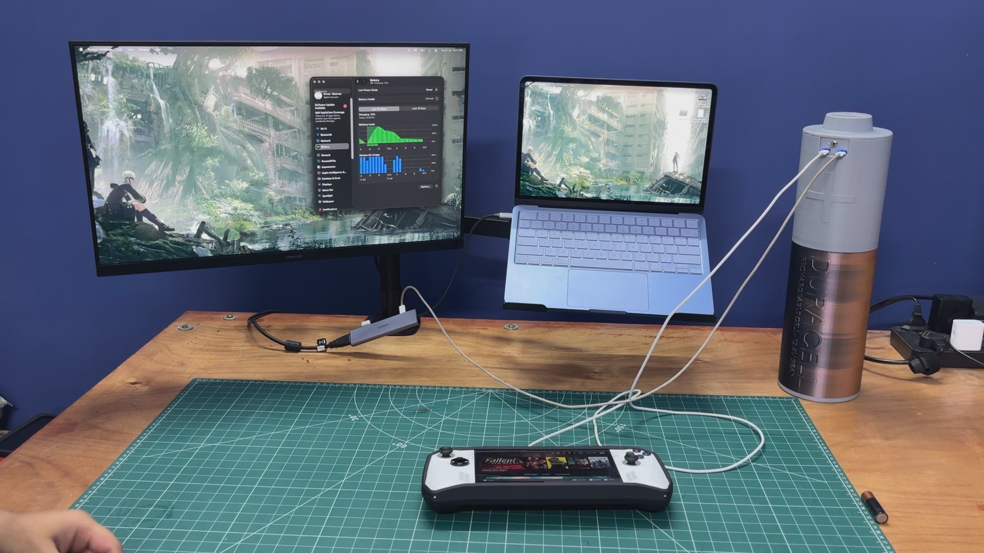
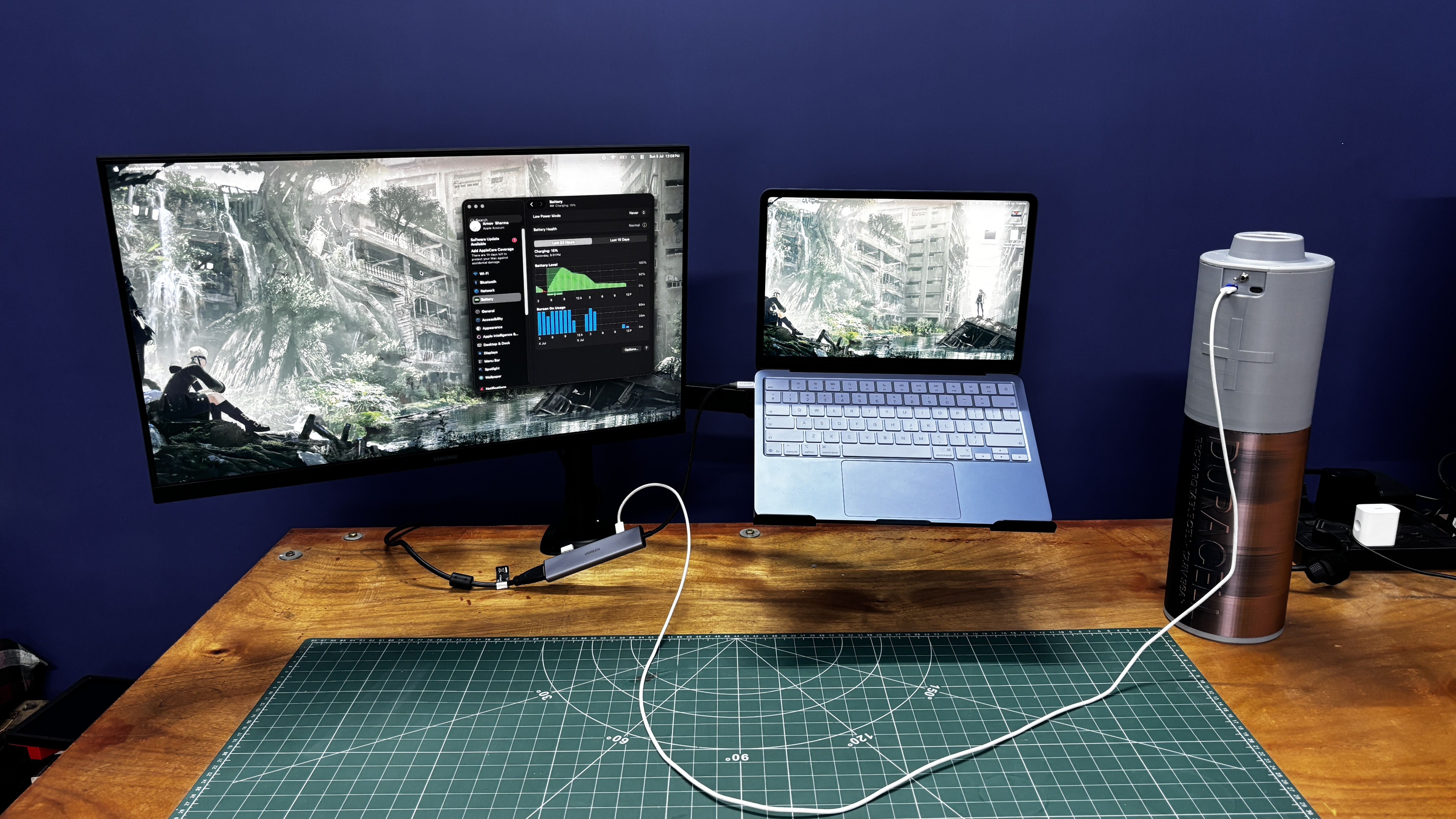
Next, I tested the onboard USB-C PD modules by connecting my MacBook with a USB-C-to-USB-C cable. The laptop started charging immediately without any issues.
I then repeated the same test with my ROG Ally, and it also charged normally through the PD module.
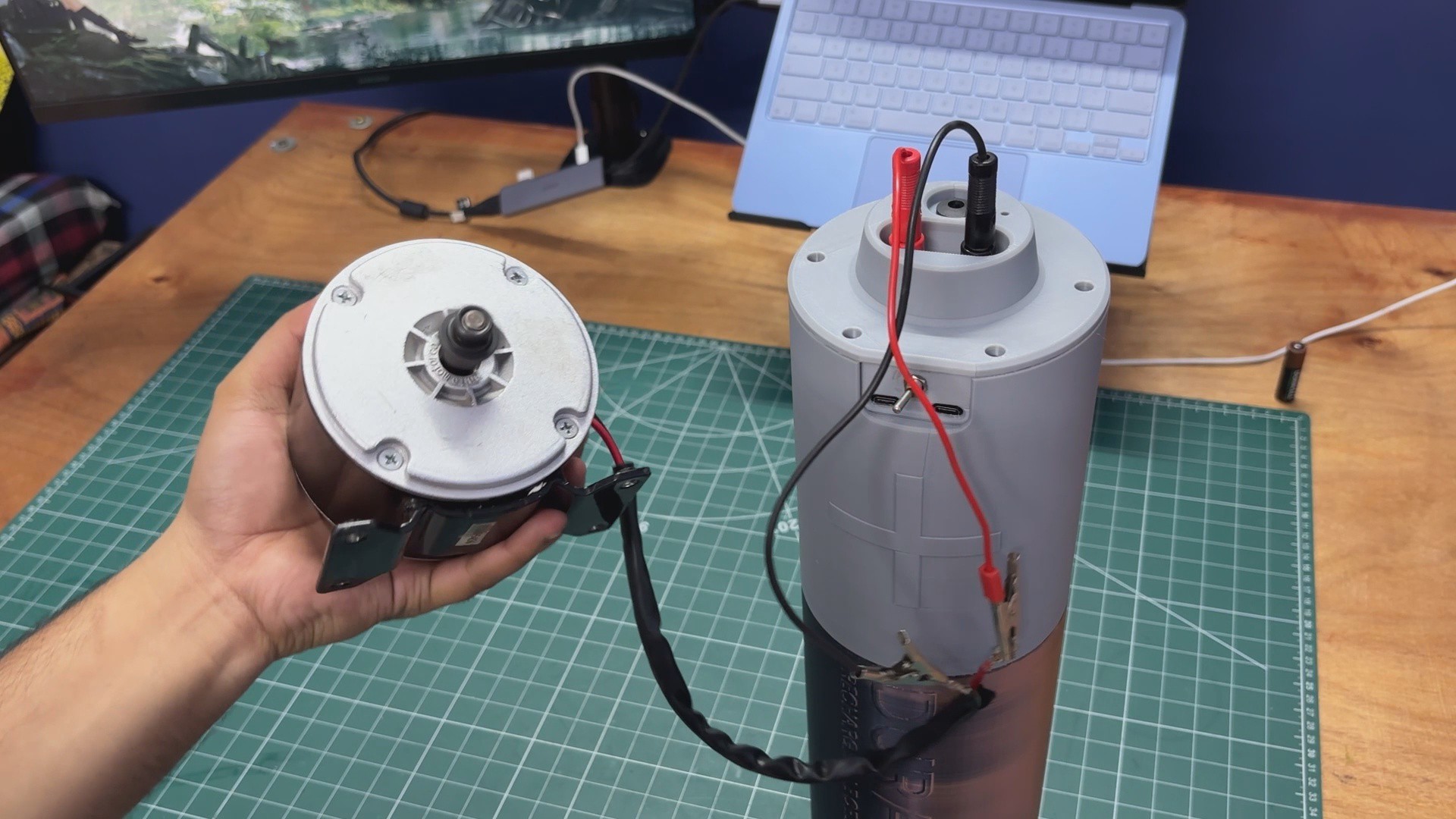
Finally, I connected a 250W e-bike motor directly to the battery pack's output. As expected, the motor ran without any problems, confirming that the battery pack can comfortably power higher-current 12V loads.
For charging the battery pack, I used a 12V 5A charger capable of delivering approximately 60W of charging power. Since the battery pack has a capacity of roughly 470Wh, a full charge takes around 8 hours with this charger.
The charging time can be reduced by using a higher-current power supply, such as a 12V 10A charger. Another option is to charge the battery pack using a solar panel. Since the BMS used in this project can tolerate charging input voltages of up to 45V, a solar panel with an open-circuit voltage below this limit can be connected. For example, a 24V, 4A (approximately 100W) solar panel would be an excellent choice for charging this battery pack outdoors.
 Arnov Sharma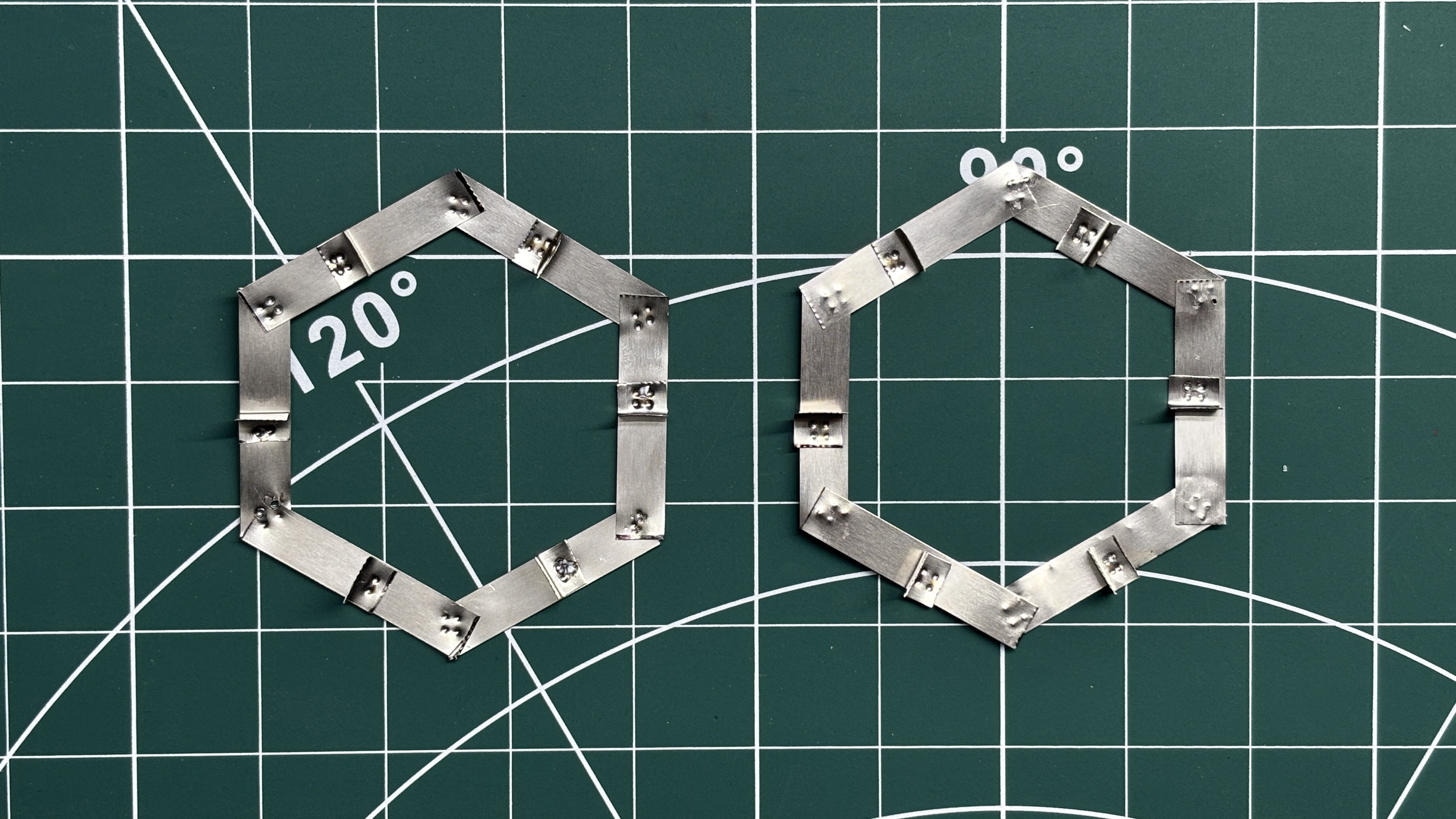
Discussions
Become a Hackaday.io Member
Create an account to leave a comment. Already have an account? Log In.