Oleg
-
TLV Protocol and Universal Message Serializer
08/08/2026 at 09:20 • 0 comments![]()
This development time was spent on designing the communication protocol between Molde modules and the main controller.
Initially, I considered using something similar to JSON with a key-value structure. However, to reduce communication overhead and improve performance, especially for more demanding modules such as displays, Bluetooth interfaces, and similar devices, I decided to develop a custom binary protocol based on the TLV (Type-Length-Value) principle.
As a result, a universal and easily scalable message serializer was created.
## Dictionary-Driven Architecture
Each module contains a descriptor table that describes all available data:
typedef struct
{
uint16_t object;
uint16_t id;
uint8_t access;
uint8_t value_type;
uint16_t size;
const void *ptr;
} descriptor_t;Each descriptor contains:
object class
object ID
access permissions
value type
data size
pointer to the actual variableFor example, the joystick module contains descriptors such as:
descriptor_t dictionary[] =
{
{ OBJECT_STATE, AXIS_X, ACCESS_RO, VALUE_TYPE_UINT16, sizeof(joystick_state.axis._x), &joystick_state.axis._x },{ OBJECT_EVENT, AXIS_XY, ACCESS_RO, VALUE_TYPE_UINT16, sizeof(joystick_state.axis), &joystick_state.axis},
{ OBJECT_METADATA, FIRMWARE_VERSION, ACCESS_RO, VALUE_TYPE_UINT8, sizeof(joystick_metadata.firmware_vers), &joystick_metadata.firmware_vers},
.......
};The message builder searches this table and automatically serializes the requested data.
This means that adding a new object normally requires only adding a new descriptor to the dictionary, without modifying the serializer itself.
## Two Message Types
At the moment, the protocol uses two basic message types.
1. Single-object message
A TLV_NONE message transfers one complete object together with its value:
TLV_NONE length OP_NOTIFY OBJECT_EVENT AXIS_X UINT16 value
This is used when the module needs to transmit an actual value or event.
2. Enumeration message
A TLV_LIST message is used for discovery.
For example, the main controller can request the properties supported by a module. The module then generates the response from its descriptor table:
TLV_LIST length OP_RESPONSE OBJECT_PROPERTY AXIS_X ACCESS_RO AXIS_Y ACCESS_RO AXIS_CENTER ACCESS_RW
The same mechanism can be used to enumerate supported commands, events, metadata, and other objects:
TLV_LIST length OP_RESPONSE OBJECT_METADATA FIRMWARE_VERSION ACCESS_RO INTERFACE_VERSION ACCESS_RO MODULE_DIRECTION ACCESS_RO MODULE_GEOMETRY ACCESS_RO MODULE_TYPE_ID ACCESS_RO
This allows the main controller to discover the capabilities of a module.
A message is identified not only by the TLV header, but also by the least significant bit of the module CAN address.
The module uses this bit to indicate the beginning of a TLV message. Therefore, the receiver use both the CAN identifier and the first TLV field to determine where a new message starts.
## Universal Message Serializer
The main message-building function is:
void message_builder(uint16_t header,uint16_t operation, uint16_t object,uint16_t tag_id);
The builder performs three main steps:
Dictionary lookup
TLV packet encoding
Transfer of the resulting binary data to the CAN transport layerThe important part of this architecture is its scalability.
Adding a new hardware module does not require changing the protocol or serializer. The module only needs its own descriptor table describing its objects and data.
The same serializer can therefore be reused for future Molde modules such as displays, LED matrices, sensors, relays, and other devices.
The communication layer remains completely generic, while the description of each individual module is contained in its descriptor table.
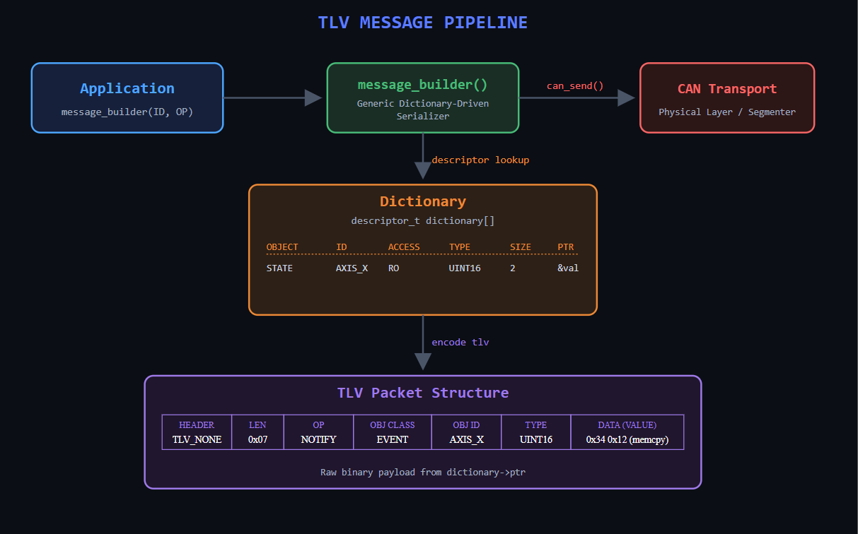
Picture 1. TLV MESSAGE PIPELINE
Dictionary-driven TLV message pipeline used by the Molde module. The application requests a message, the serializer performs a descriptor lookup, generates the binary TLV packet, and passes it to the CAN transport layer.
A message is identified not only by the TLV header, but also by the least significant bit of the module CAN address.
The module uses this bit to indicate the beginning of a TLV message. Therefore, the receiver use both the CAN identifier and the first TLV field to determine where a new message starts.
This provides an additional framing mechanism at the CAN transport level, while TLV_NONE or TLV_LIST defines the structure of the payload itself.
One step closer. See you in the next update.
-
Experimental Module Prototypes
07/24/2026 at 13:52 • 0 commentsToday Molde reached another important milestone.
## Modules.
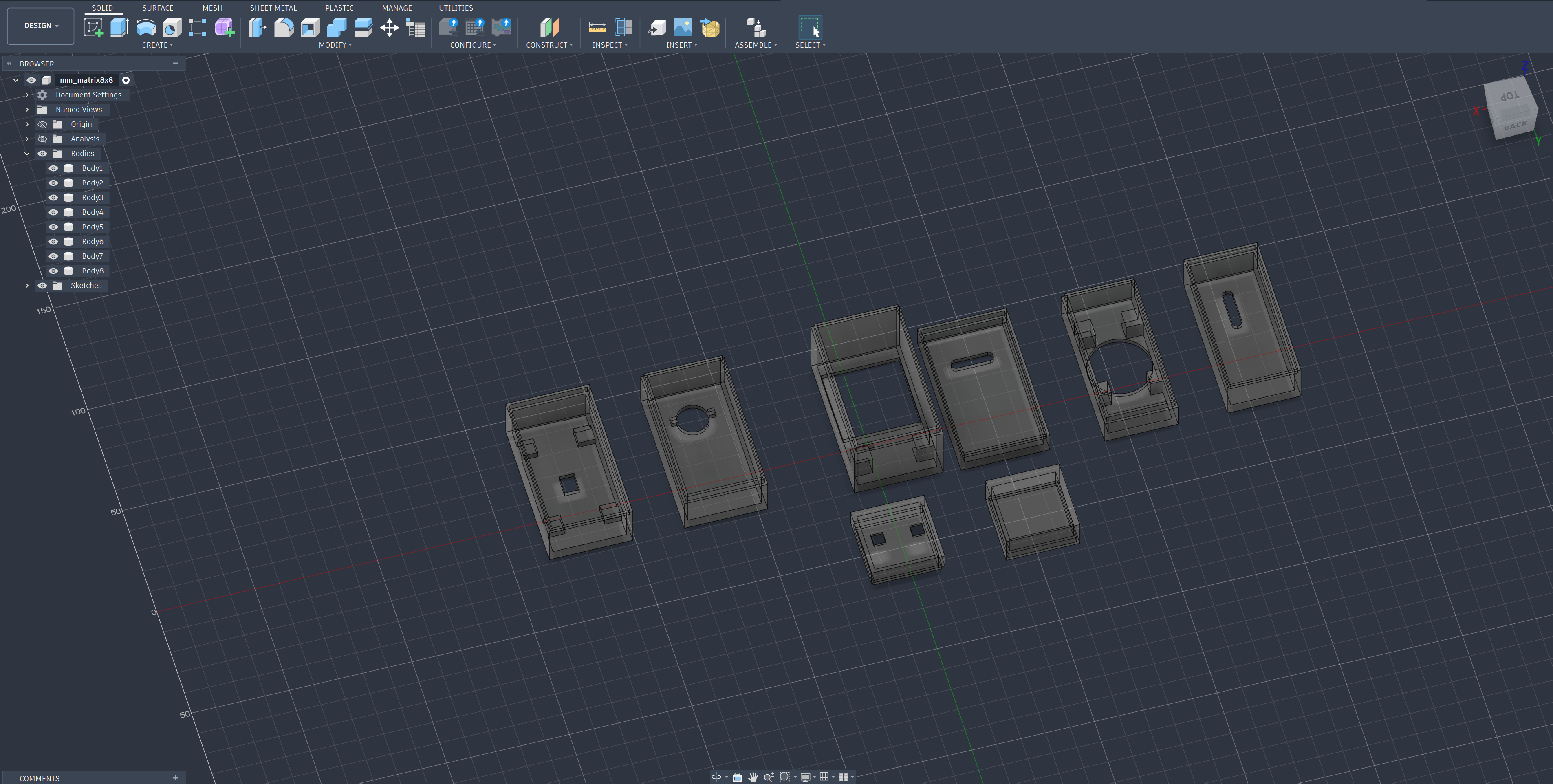
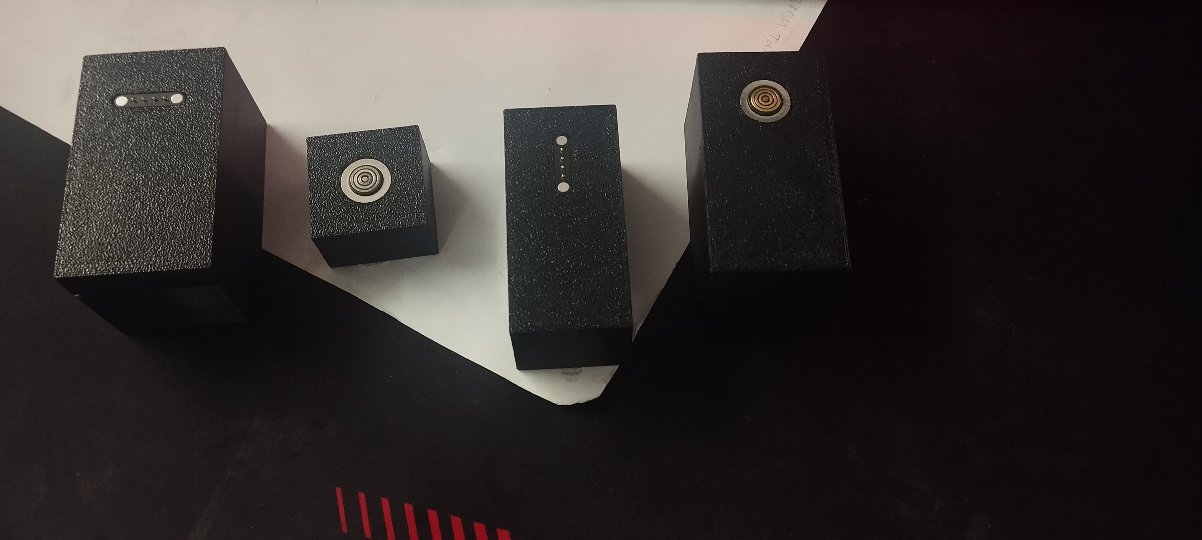
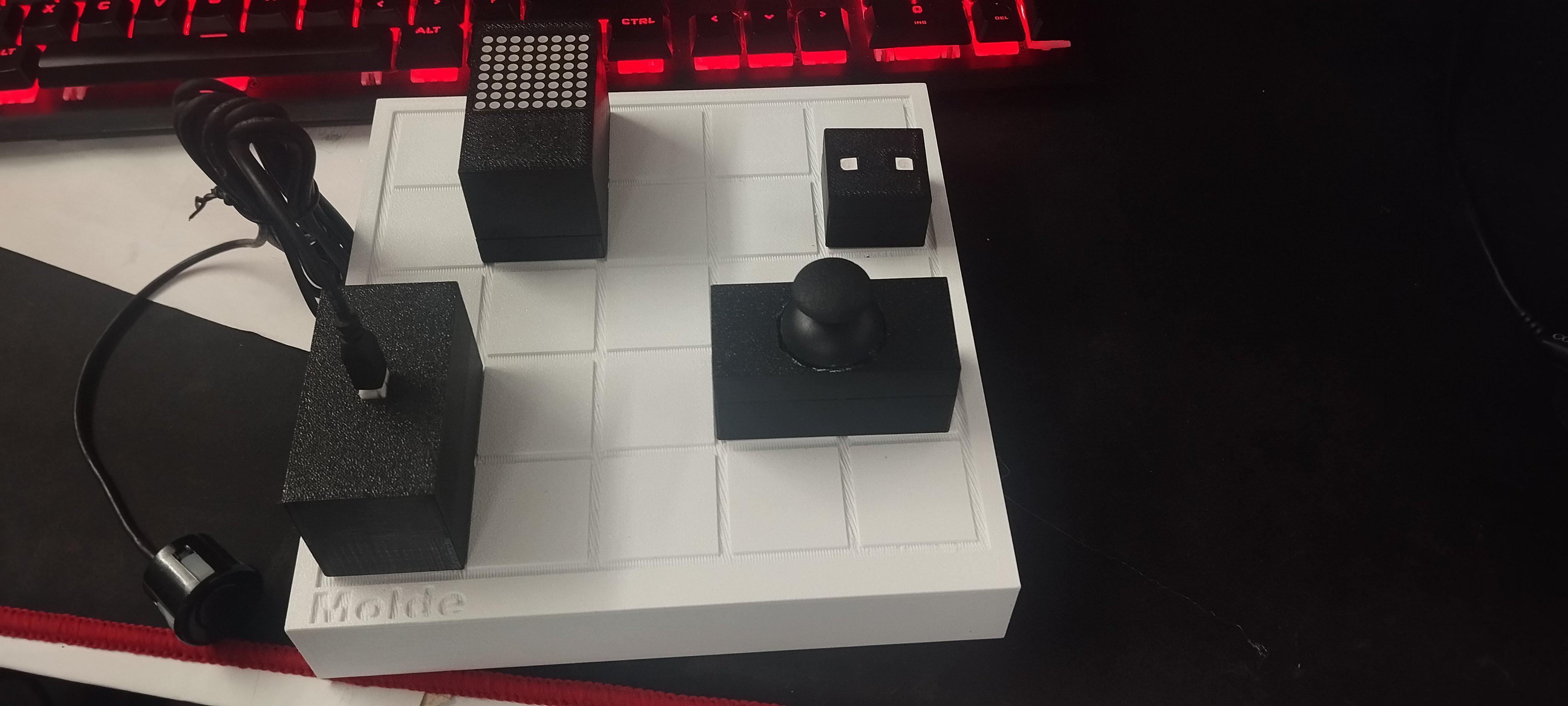
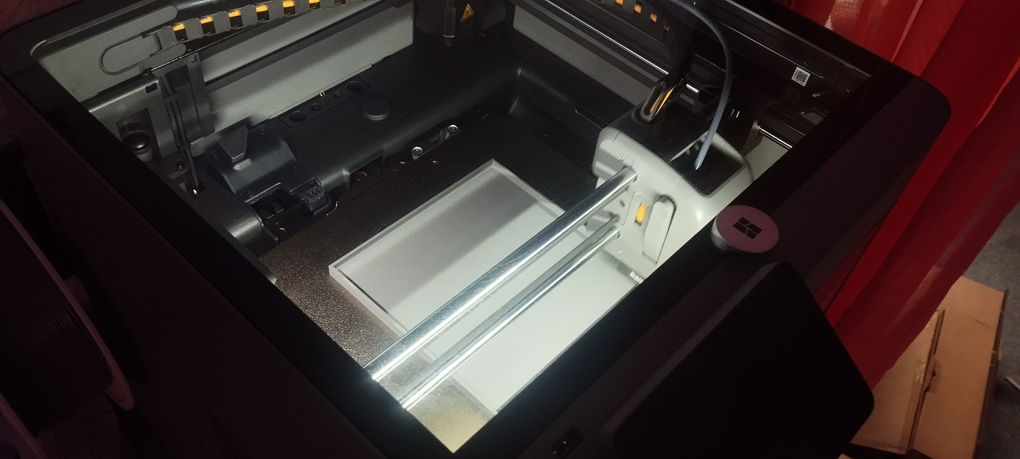
The first set of experimental modules has been designed and 3D printed. These are not intended to become final products—they are simply test platforms for evaluating mechanics, connectors and future electronics.
![]()
![]()
At the moment I have 4 magnetic connector pairs available only, so I builded 4 different modules. Some are designed as 1×1 modules, while others occupy 1×2 cells. Supporting different module sizes has been part of the concept from the beginning.
Current modules:
2-axis analog joystick with push button
8×8 LED matrix (MAX7219)
Ultrasonic distance sensor
Dual RGB LED module.
I use MCU CH32V203 for driving each module ( any recommendations?).
## The Main Panel Evolves
First printed panel 25×25 mm grid but after that I redesigned the base and increased the cell size to 30×30 mm. It already feels more comfortable, but I'm still not convinced this is the final size.
Possible directions:
reduce to 20×20 mm;
increase to 35×35 mm;
keep 30×30 mm but change the spacing between cells.
## Connector Evaluation
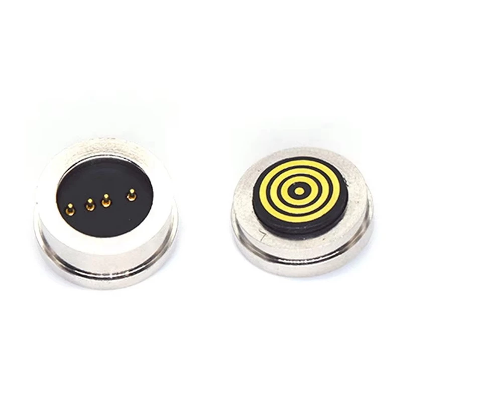
One of the big open question is still the magnetic connector.
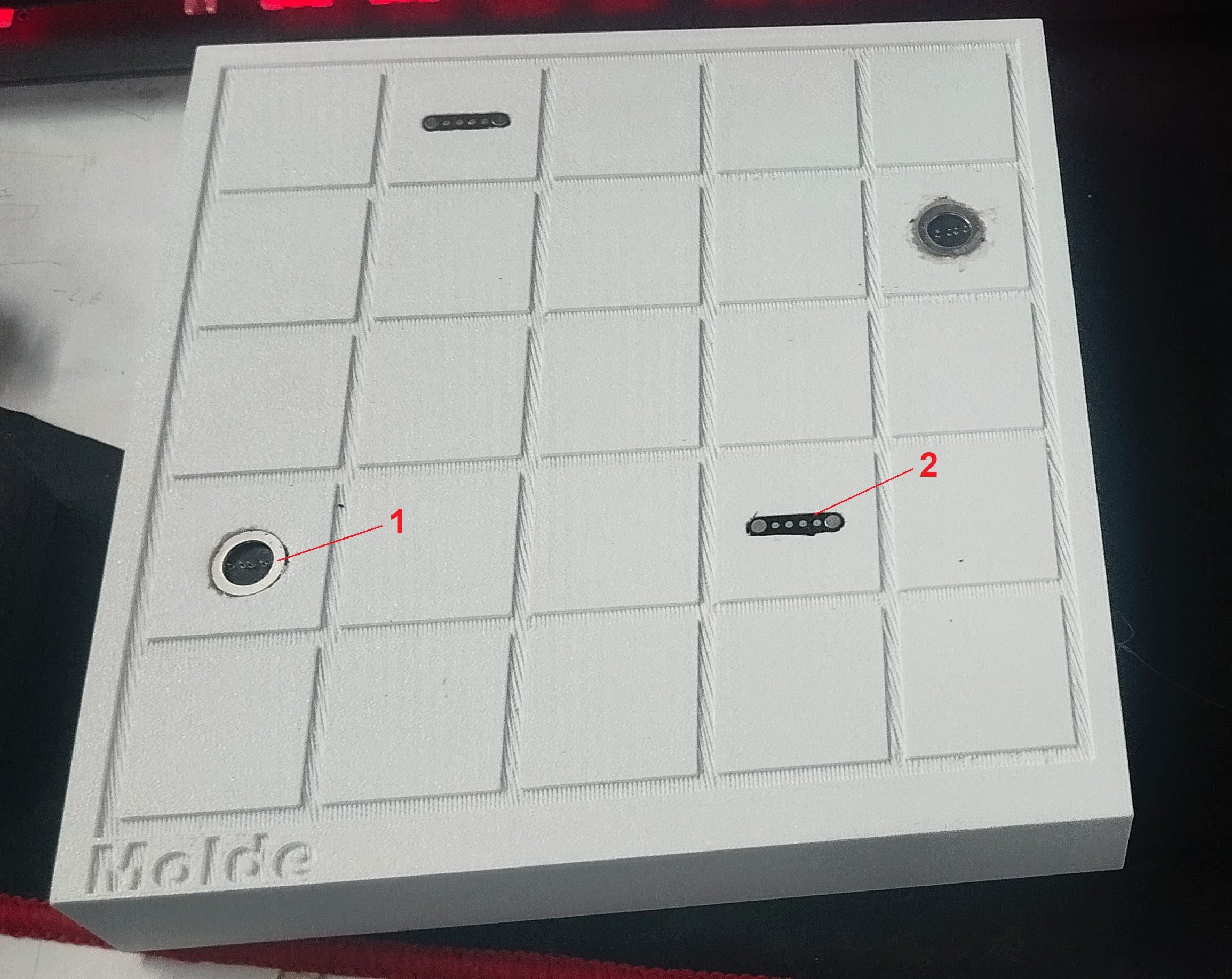
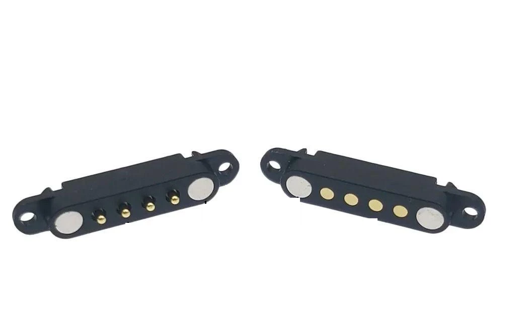
So far I'm testing two different concepts.
![]()
Type 1 — Circular connector
allows free module rotation.
Type 2 — Linear connector
noticeably stronger magnetic attraction;
aligns modules much more accurately.
At this point I honestly don't know which solution is better. The circular connector offers more freedom. The linear connector offers better precision.
![]()
## Next Steps
Develop the initial firmware for the CH32V203-based modules.
Assemble the electronics for the Main Board prototype.
One step closer. See you in the next update.
-
The First Physical Prototype
07/18/2026 at 17:37 • 0 commentsToday Molde took its first physical form.
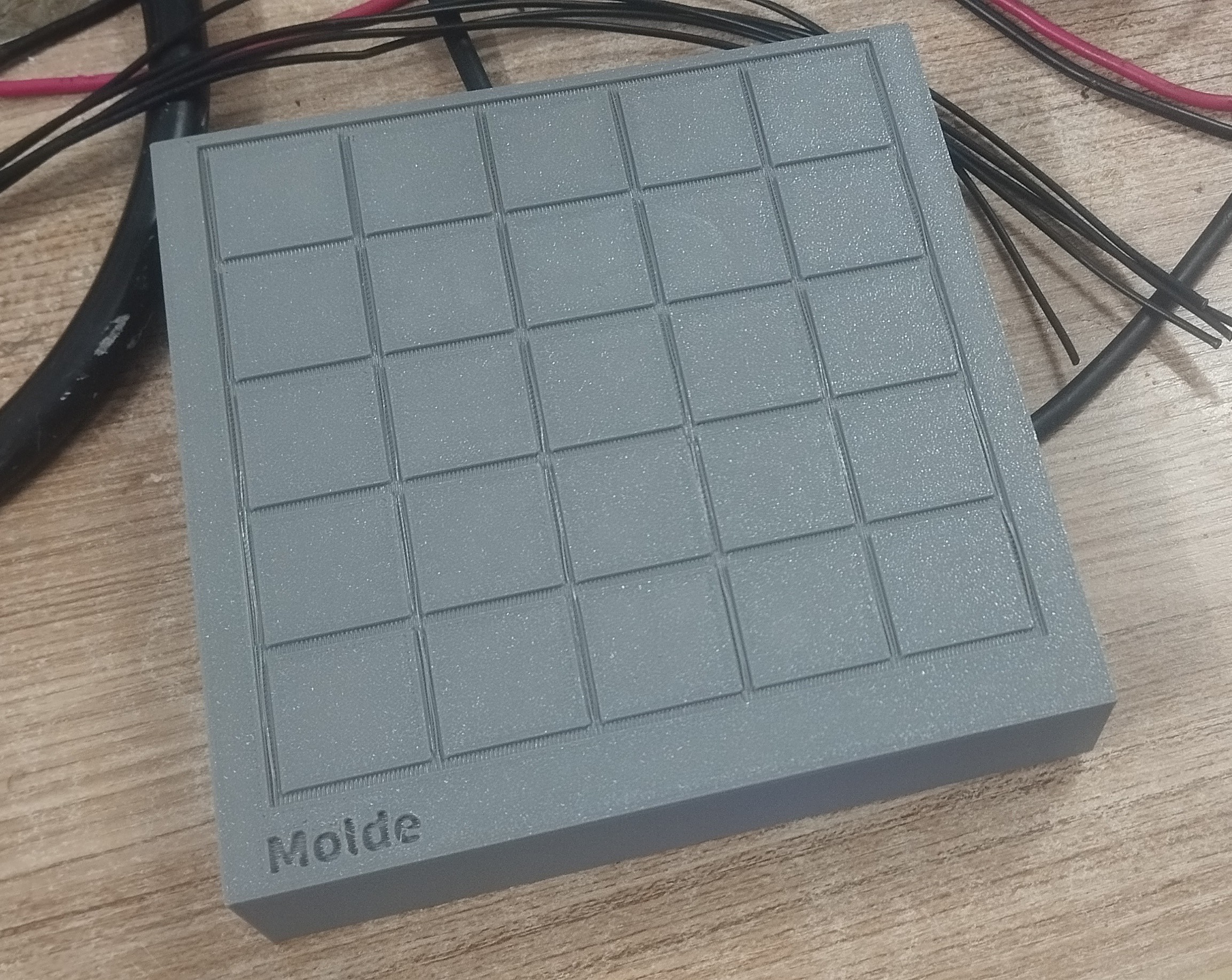
I 3D printed the first 5×5 prototype panel...
![]()
![]()
The panel uses a 5×5 grid with 25×25 mm cells.
Im not sure about size yet but anyway its a good starting point.
The next step is turning this mechanical prototype into an interactive hardware platform.
## Connector Evaluation
I also ordered two different types of magnetic connectors for evaluation.
![]()
![]()
Each one has pros and cons. Will see
## Next Steps
Design the first test modules.
3D design and print boxes.
Try to Integrate both connector types.
Evaluate electrical reliability and holding force.One step closer. See you in the next update.
-
Project Goals
07/17/2026 at 15:50 • 0 comments![]()
# Project Goals
Molde has begun.
This project is still at a very early stage. There are no working prototypes yet, and many engineering decisions are still ahead.
The purpose of this log is to document the initial goals of the project before development begins.
## Main Goals
- Create a modular hardware platform.
- Use magnetic modules that can be placed anywhere on the panel.
- Build a universal interactive base with reusable hardware modules.
- Make the platform open source.
- Keep the system simple enough for beginners, yet powerful enough for experienced developers.## Long-Term Vision
Users should be able to assemble, rearrange, and reuse hardware modules within seconds.
## Current Status
At the moment, I have:
- the initial concept;
- several ideas that need to be validated.The next step is to validate the core mechanical and electrical concepts before designing the first Main Board.