Close
0%
0%

Walking Machine

Almost everyone has seen images/videos of Theo Jansen's walking machine, the "Strandbeesten". Here I want to look at a simplified version.

Similar projects worth following
Development of a 4 bar walking machine.

The Walking Machines

-

Theo Jansen designed and built the Strandbeest, a walking machine:
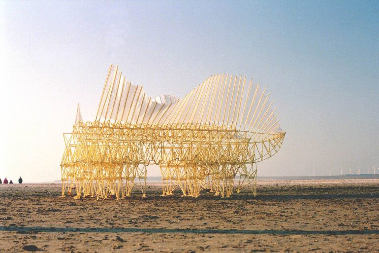
Title: Strandbeest walking on the wind

Currens Ventosa, Oostvoorne NL 1993, photo: Adriaan Kok

Source: https://www strandbeest.com/strandbeest/1993-currens-ventosa

-

There is an excellent website (DIY Walkers) that discusses the Jansen linkage and has a web simulation for experimentation (Source: https://www diywalkers.com/strandbeest.html).

This site covers (among others) the Jansen's (8 bar) linkage, the Klann's (6 bar) linkage and the 4 bar linkage.

-

The Jansen 8 Bar Linkage

Here is an example of Jansen's 8 bar linkage using the DIY Walkers web simulation:
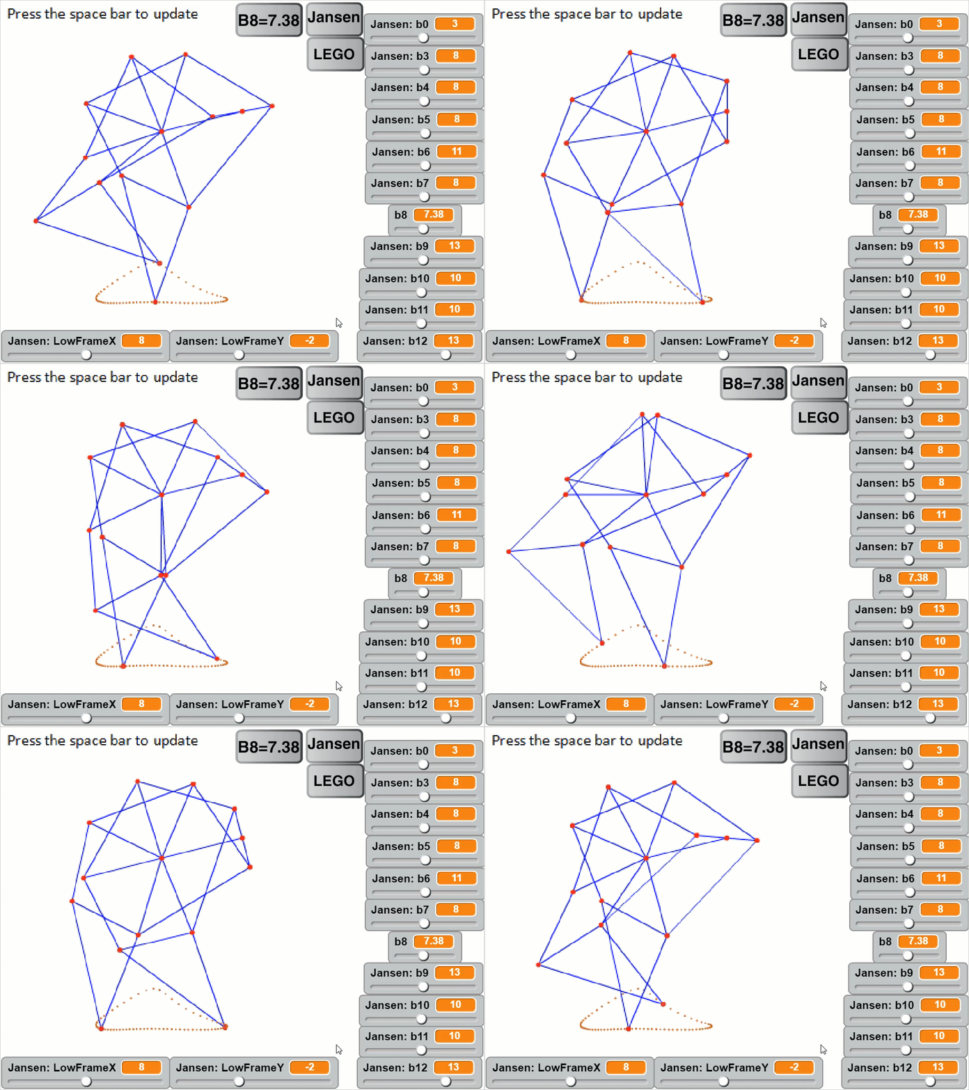
Picture

Source: https://www diywalkers.com/uploads/5/3/3/9/53394177/strandbeest-simulator-6_orig.gif

-

The Klann 6 Bar Linkage

Here is an example of Klann's 6 bar linkage (the "crab walker"):
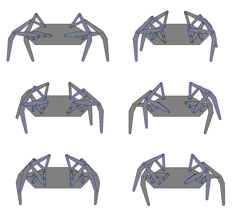
Source:https://www diywalkers.com/uploads/5/3/3/9/53394177/f4-motion_orig.gif

Note that the rear legs need to walk backwards.

The foot trace should be but may not be symmetrical.

-

The 4 Bar Linkage

Here is DIY Walker's version of the 4 bar walker:
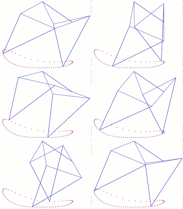
Source: https://www diywalkers.com/uploads/5/3/3/9/53394177/f4-motion_orig.gif

Note that the foot trace in not symmetrical here.

--

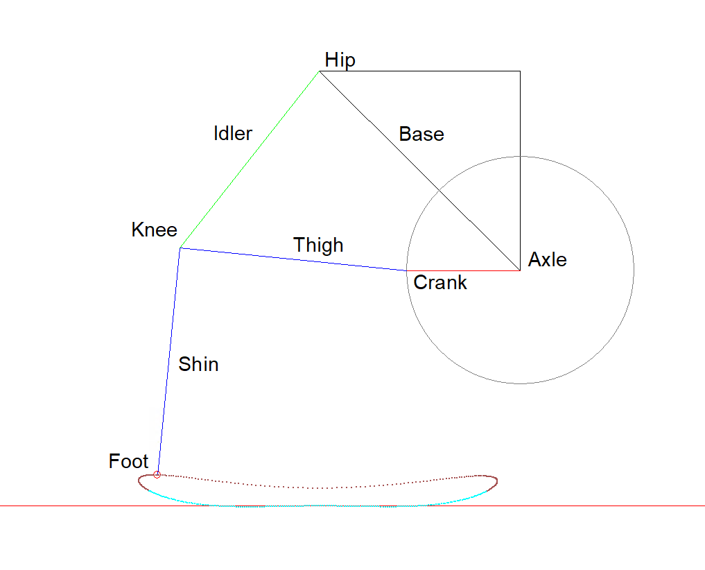
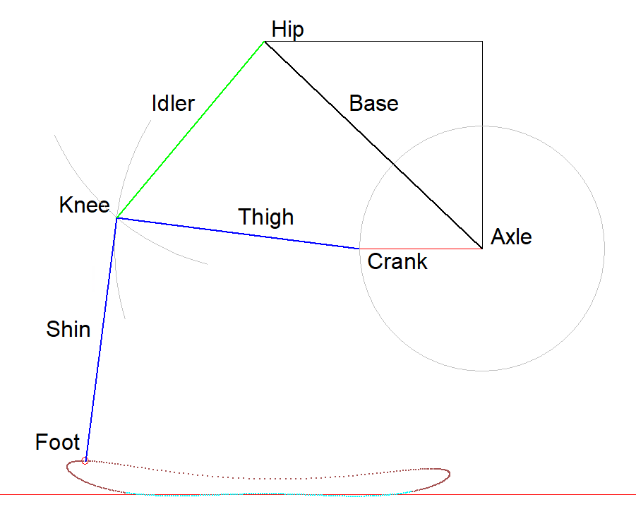
Here is my copy of the 4 bar linkage:
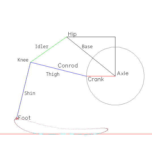
The bars are:

  1. The (black) fixed Base (Axle to Hip)
  2. the (red) Crank (Axle to Crank)
  3. the (green) Idler between the Hip and Knee
  4. the (blue) Leg consisting of the Thigh (Crank to Knee) and the Shin (Knee and Foot).

Note that the Knee angle (90 degrees) is fixed.

-

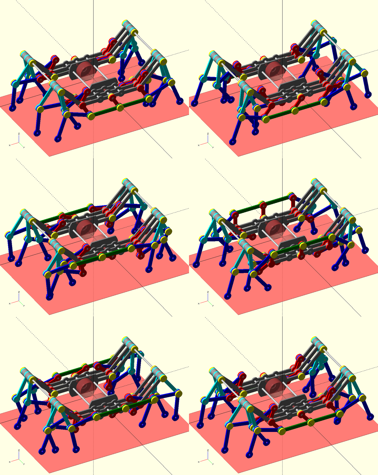
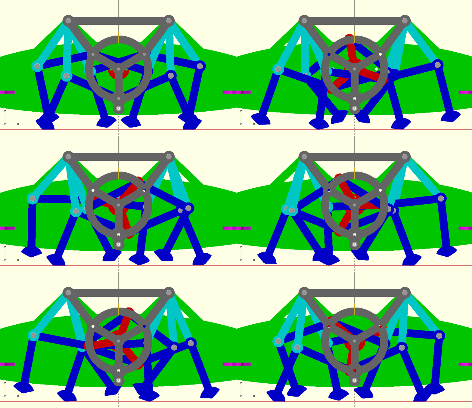
This is where my journey begins.
  • Refactoring the Walker to fit 250 mm threaded rods

    agp.cooper08/17/2026 at 07:10 0 comments

    Refactoring The OpenSCAD Model

    -

    Found a thin M3 nut (1.65 mm thick), these are used as locking nuts.

    I already have 1.25 mm thick PTFE (6.0 mm diameter) M3 bushings.

    So swap out the old components to see it I can use the 250 mm threaded rod that I already have.

    Great, it works. Added the excess savings to the body width so I can install and remove the stepper motors after the body has been glued up.

    I will have to check the actual widths of the nut and bushing before ordering the lasercut parts.

    -

    Next is to replace the disk foot with an optimal foot. I can import a DXF into OpenSCAD for this.

    Currently reworking the Optimisation Code to optimise the Foot at the same time as the Walker Geometry. Many hundreds of line of code to rework so it takes time.

    -

    After, examining the the animation of the first optimal foot design, I noticed that the toe of the foot stabbed the floor on the return stroke!

    So I fixed the minimum return stroke lift (5 mm) and practically destroyed the down foot stroke improvement:

    -

    I could have just just used a point for the foot.

    Still, a combine optimisation has potential to improve the down foot stroke.

    -   

    After several days of reworking the optimisation code, some preliminary results.

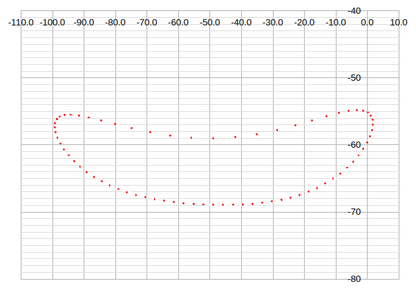
    First was to use the current optimal model and the impact of the optimal foot:

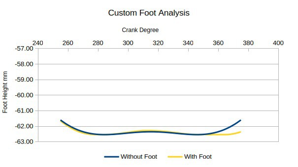
    The main improvement was the extension of the useful window to the rear (to the right) of the down stroke. To take advantage of this I need to recalculate the 120 degree window, and then optimise.

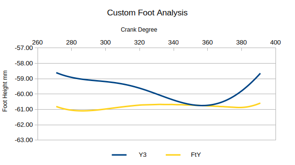
    Here is the result of optimisation if the window is not moved and the other constaints are  removed:

    Not ideal, as the non-custom foot curve (Y3) is worse but compensated by the custom foot.

     Still the oscillation of the down stroke has been reduce.

    -

    Finished the the Optimisation code.

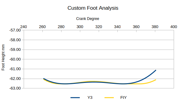
    Best option seems to be taking the current optimisation and sliding the foot down window:

    -

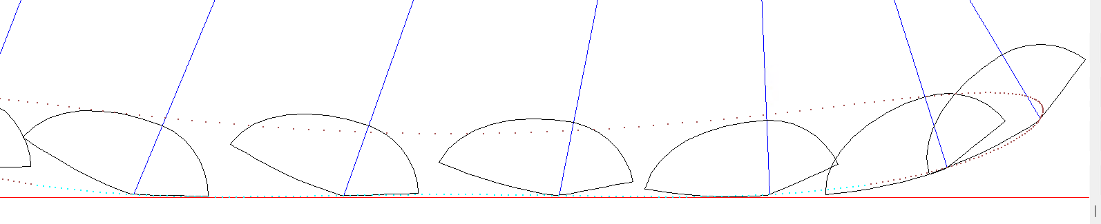
    The foot peak to peak "wobble" has been reduced from 0.94 mm to 0.48 mm:

    -

    AlanX

  • Side Projects

    agp.cooper08/16/2026 at 02:22 0 comments

    Side Projects

    -

    There are a lot of side projects and check work to be done.

    There are uncertainties in the process that need to be reduced.

    Examination of fall back positions if the preferred option fails.

    And lots of new areas to explore.

    -

    Fall Back Options

    -

    The preferred option is to use inference fits and loose fits.

    The problem is the lack of control over the tolerance of online laser cutting.

    The next option is to glue the crank axle and crank pin to the rod.

    If that fails then the fall back is the use thread rod and nuts:

    -

    Two 3D (OpenSCAD) designs have been completed to cover the options.

    -

    Part Orders

    -

    Most parts (nuts, bolts, rods, washers, bearings etc) have been ordered (from China),

    but this can take up to six weeks  to arrive.

    Even then the parts may not be suitable.

    For example, the longest M3 threaded rod I could get was 250 mm long.

    The thread rod and nut version of the design needed a 312 mm long.

    There are solutions but the parts need to be ordered.

    -

    Reoptimisation

    -

    I have used a steepest descent optimiser for this project.

    They are not straight forward as the error function and constraints are rather tricky to setup.

    One constraint (sub-goal) that was critical for good solutions was to enforce symmetry.

    Indirect methods did not work. Balancing the competing sub-goals was more important than expected.

    The error functions also needed to be quite specific.

    -

    Until recently I thought that my optimisation was complete, with this solution:  

    • Bar 1: Base Plate Points
      • Axle
        • PX0 =  0.0
        • PY0 =  0.0 
      • Hip Pivot:
        •     PX1 =-53.0
        •     PY1 = 53.0  
    • Bar 2: Crank
      • L0 =  30.0
    • Bar 3: Conrod (leg thigh)
      • L1 =  60.0
    • Bar 4: Hip Bar
      •     L2 =  60.0  
    • Bar 4: Extension (shin)
      • L3 =  60.0   Leg (shin)
      • A3 =  90.0   Knee Bend

    -

    Foot Optimisation

    -

    Struggled to work out how to do this. Not that I did not know the general shape.

    The problem is the solution is specific to the walker design:

    Finally worked out a method:

    But now I have to reoptimise the foot with the walker at the same time.

    After this reoptimisation, I will get the parts lasercut.

    -

    Boolean Shape Options for DeltaCAD

    -

    Delta CAD is now deceased. A shame!

    It has a persistent menu system that reduces the cost  key strokes and mouse clicks.

    Unfortunately the menu system was half finished. Still, it is very nice to use.

    While the GUI works with Linux just fine, the macro language does not.

    Now I run DeltaCAD in a VM. With two menu bars visible at all times, it is just one click to switch between Windows and Linux.

    After using OpenSCAD, I really like the boolean operations: union(), difference(), intersection().

    So I used Alan Murta's Generic Polygon Clipper (GPC, 2004) code and wrapped a DeltaCAD macro around it.

    It's magic, select a couple of shapes, run the macro, select your option, and a few seconds later, the selected shapes are replaced by the boolean operation shape.

    It saves so much time spent moving shape points over other shapes.

    Acrylic Glue

    -

    Acrylic glue is very different to normal glue. It is very fluid (low viscosity) and wicks into the joints by capillary action.

    I have bought a kit ($$$) so I am set for the Walker's acrylic  body assembly: 

    -

    I am hoping with the right tools the process will be magic.

    -

    AlanX

  • Designing the Body

    agp.cooper07/27/2026 at 09:58 0 comments

    Designing The Body

    -

    I have started designing the body. First thoughts is a bumper bar:

    It serves several functions:

    • A floor to the battery and micro-controller board.
    • Protection for the legs (they look rather fragile).
    • A sensor platform.
    • A structure to increase rigdity.

    I think I will need to extent the motor plate forward and aft, to reinforce the bumper bar floor.

    -

    I have selected 2 mm thick PTFE M3 washers.

    Bought the rods and pins.

    Bought the Nema 14 round steppers.

    A couple for the motor shaft (5 mm) to the drive shaft (3 mm).

    -

    I looked at buying M3 collars but after a long consideration, stayed with gluing the "fixed" rods/collar to the shafts.

    -

    While there are commercially  available stepper drivers, a long long time ago I built discrete drivers based on TTL logic:

    transistors - Totem Pole Output Driver - Electrical Engineering Stack ExchangeI seem to remember that I added protection diodes between ground and the output, and the output to the power supply.
    The input transistor was not used but looks like a good idea.

    -

    For the micro-processor I feel rather retro. As in the vein of "How to build your own working robot pet." by Frank DaCosta. A book I repurchased after more than 40 years. So I am looking at the Intel 8085.

    -

    When I look at the bumper bar, I could add a nose and it would look like a dog from above!

    That is the bumper bar looks like a head and a set of ears, all it needs is a snout and a nose,

    -

    I started this project on the 28th of June so tomorrow is one month.

    -

    Its been a few days with some success and failures to report:

    • Good progress on refactoring the code, getting slot and tab working:

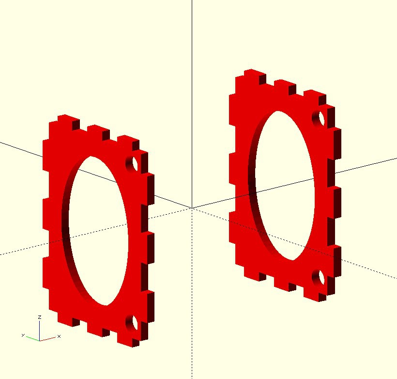
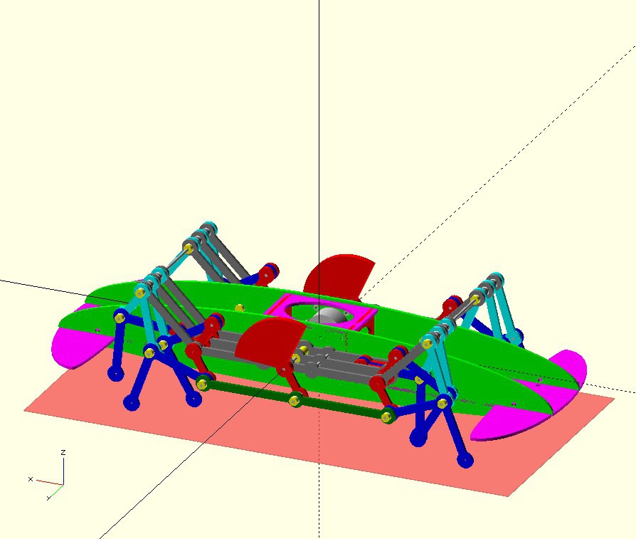
    If you wondering, the big holes in the carriage torsion box,  are used to get access to the stepper motors.

    Balancing the Rotating Mechanisms

    I looked at a balancing the crank:

    The double thickness counter balance matches weight and centre of mass so should work okay.

    -

    Here is my first pass counter balance design:

    -

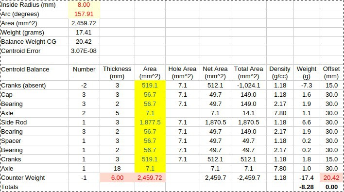
    Recalculated the counter balance weight (as best I could):

    Made the counter weight balance small as practical, but no allowance for reciprocating parts. 

    Usually an allowance of 50% to 90% of the moment of these parts is made (for internal combustion engines).

    -

    Bugs in OpenSCAD

    Bug in OpenSCAD are silent (but Syntax errors are noisy).

    -

    To implement Slot and Tabs, I wrote Function Slots(). Easy enough, create some slots, translate them to the edge in question and take the difference:

        // Add Slots for Bulkhead
        mirrorCopy([1,0,0])
        translate([cgap/2-5,0,0])
        rotate([0,0,90])
        slots(wgap,plateThick,3);

    -

    Worked fine until it does not!

    Spent a day working through this, the answer was a vertical version of slots to avoid the rotation: 

    -

    Slotting

    The slotting code work with odd and even matching slots or tabs:

    // Make Slots for edge joins
    module xslots(l,d,n) {
      let(m=n%2)
      let(w=l/(2*n+2*m-1))
      for(i=[1-n:2:n-1+0.001])
      translate([i*w,0,0])
      cube([w+0.01,d+0.02,3*d],center=true);
    }
    
    module yslots(l,d,n) {
      let(m=n%2)
      let(w=l/(2*n+2*m-1))
      for(j=[1-n:2:n-1+0.001])
      translate([0,j*w,0])
      cube([d+0.02,w+0.01,3*d],center=true);
    }
    

    -

    For example, adding slots and tabs using  tab = 3 and slots  = 4, to bulkheads:

      // Add Bulkheads
      color("Red") mirrorCopy([1,0,0]) { 
        translate([cgap/2-5,0,0])
        rotate([0,90,0])
        difference() { 
          cube([wgap,mgap,plateThick],center=true);
    
          // Add Tabs on Sides
          mirrorCopy([1,0,0]) 
          translate([wgap/2-plateThick/2,0,0])
          yslots(mgap,plateThick,4); // 4 slots and 3 Tabs
    
          // Add Tabs on Top and Bottom
          mirrorCopy([0,1,0]) 
          translate([0,mgap/2-plateThick/2,0])
          xslots(wgap,plateThick,4); // 4 slots 3 and Tabs
        }
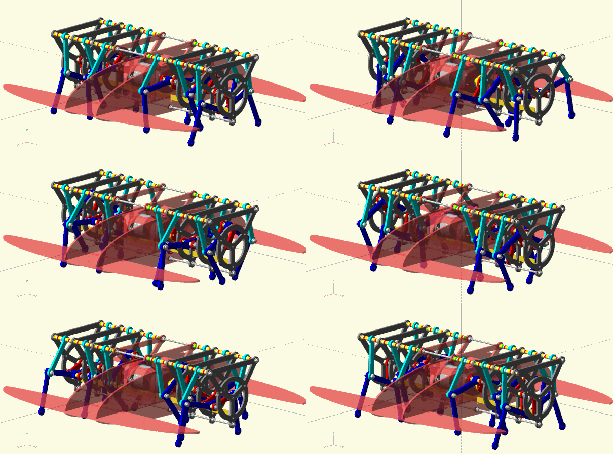
      }

     -

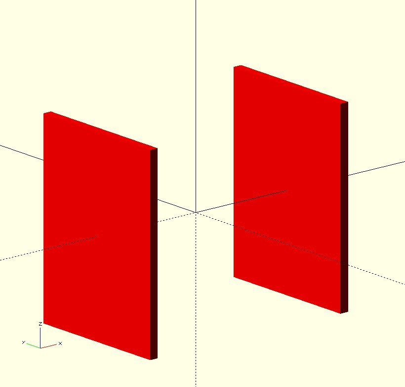
    First the bulkheads with edges oversized:

    -

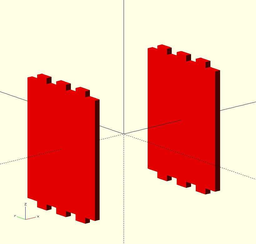
    First set of slots cutout:

    -

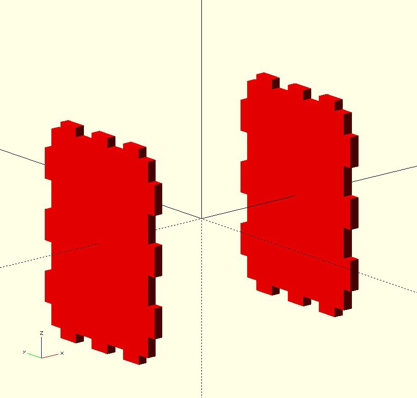
    Second set of cutouts:

    -

    Other cutouts:

    -

    So the trick here was to use n=3 for tabs and n=4 for slots, keeping d=depth and l=length the same.

    Note: (1,2) and (3,4) and (5,6) etc, are matching sets. 

    Now some matching slots in the Top:

      color("Magenta") translate([...
    Read more »

  • Building an OpenSCAD 3D Model and Animation

    agp.cooper07/22/2026 at 08:48 0 comments

    Learning OpenSCAD (work in progess)

    -

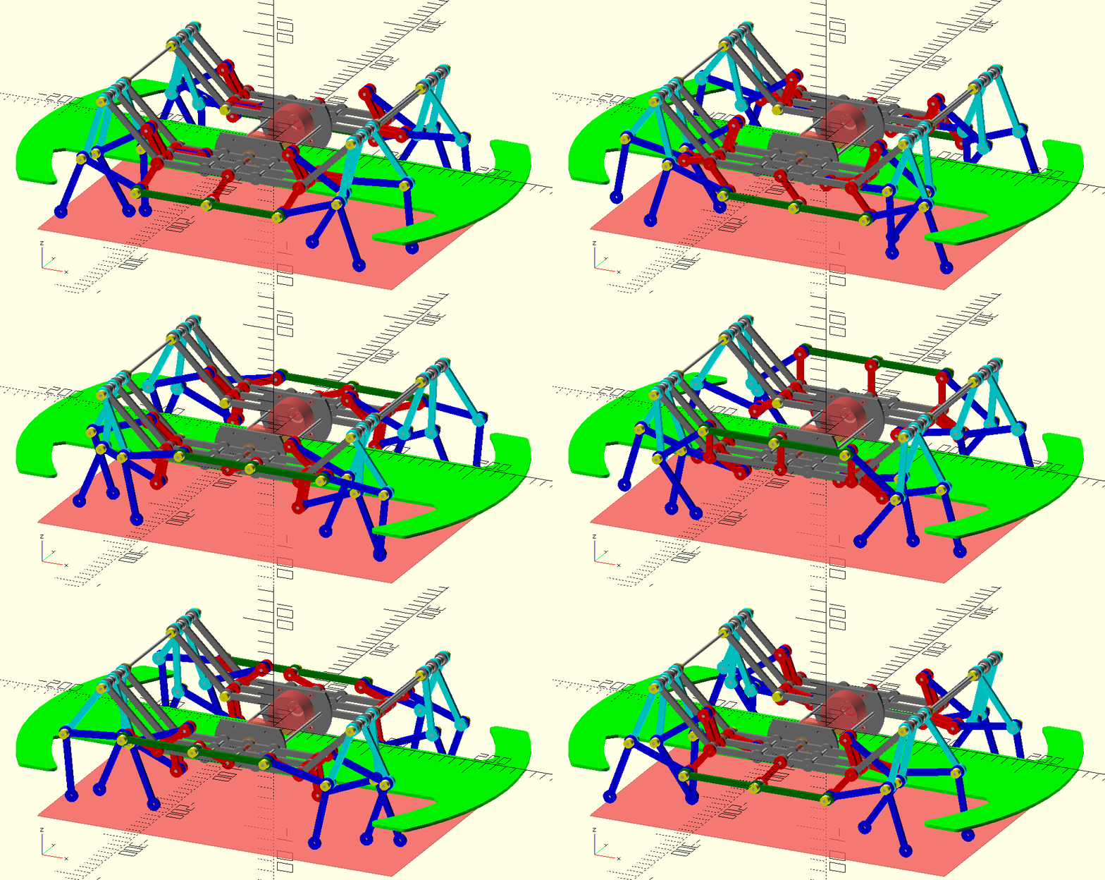
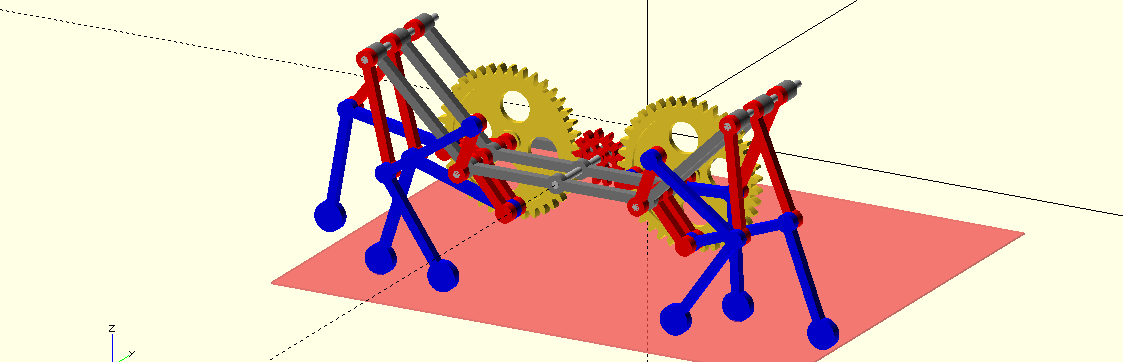
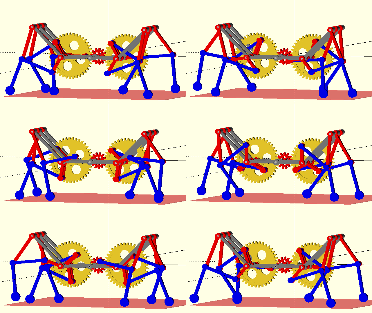
    Using the WikiBooks OpenSCAD User Manual Strandbeest (https://en_wikibooks.org/wiki/OpenSCAD_User_Manual/Example/Strandbeest), as a base, I reworked the code (it has lots of bugs) for a 4 Bar and add

    3D offsets.

    It is still a work in progress:

    -

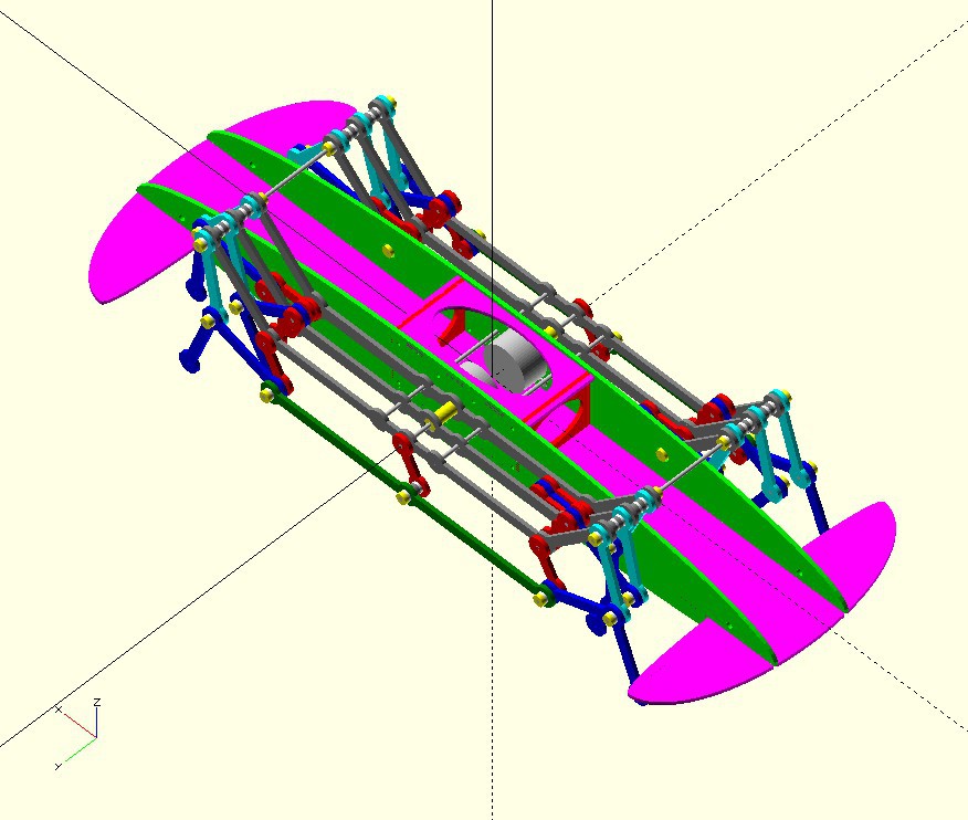
    Here is a 3D GIF of a three leg walker (one side):

    -

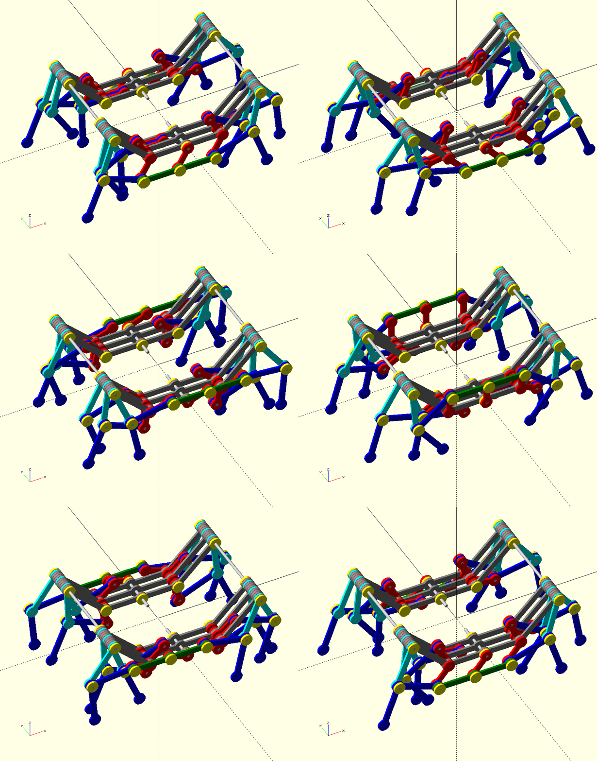
    Removed the cogs and replaced with a side crank. Only one of the axles need to be driven:

    -

    Next is to add spacers or washer between moving parts:

    -

    Notes:

    • The two colours Red and Yellow are inference fits to the rods. The other as sliding fits.
    • The spaces are 25% of the plate thickness but this is not that important.
    • The design has been changed to a "side-rod" drive. The two driven shafts are now centrally located.
    • Now I need to design the motor mounts and the internal cargo space.

    -

    Update:

    • Refactored the code to make creation more systematic and easier to debug.
    • Replaced most of the individual spacers and shim code with a function and a list.
    • Added cross-rod reinforcements and motor mounts (had to make the body a little longer).
    • To coupling the motors to the drive rod, I will use a flexible tube.

    -

    Refactored the code and removed hacked code. Now able to rebuild with parameters except for the stepper motor. Cool to be able to shop online for some Teflon washers and adjust the walker for the washer thickness that was available. 

    To do:

    • Controller board mounts.
    • Battery mounts.
    • Sensor mounts.
    • And more.

    AlanX

  • Optimising the 4 Bar Linkage

    agp.cooper07/22/2026 at 05:44 0 comments

    Optimising What Exactly?

    -

    It is not easy to optimise most problems have:

    • multiple local optima
    • multiple objectives
    • objective functions may result in degenerative (useless) solutions
    • constraint functions may result in degenerative (useless) solutions
    • the need to start with a feasible solution

    The process involves mapping out the feasibility areas and then focusing in on the most important objectives that result in the best solution.

    -

    Finding an initial feasible solution

    Fortunately we can start with DIY Walkers solution (but at half scale):

    • Axle: (0.0 mm,0.0 mm)
    • Hip:  (-48.0 mm,33.0 mm)
    • Crank L1: 30.0 mm
    • Thigh L2: 60.0 mm
    • Idle    L3: 40.0 mm
    • Shin   L4: 70.0 mm
    • Knee Angle: 90.0 degrees

    -

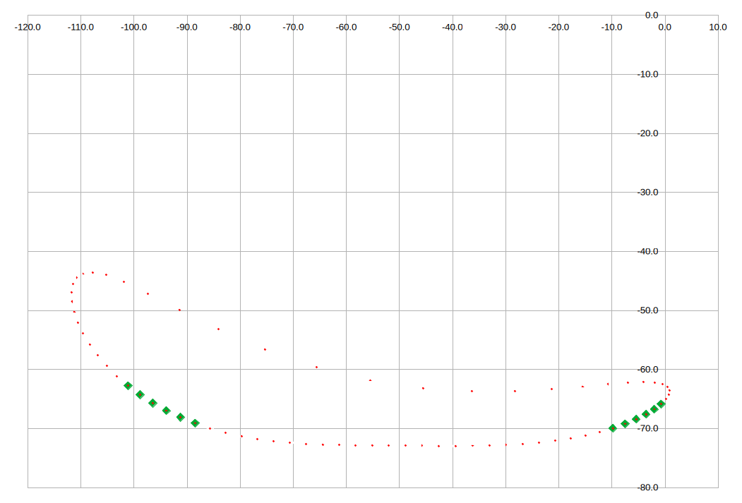
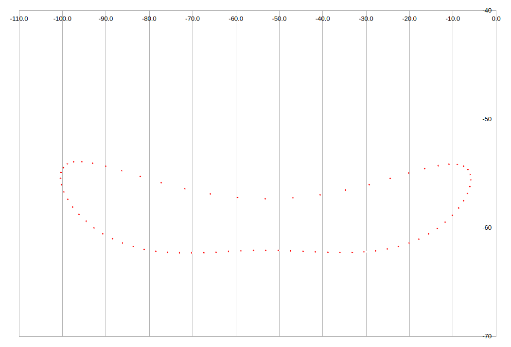
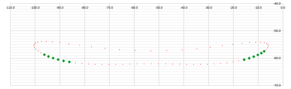
    Here the foot trace down range is 120 degrees between the green markers and 180 degrees inclusing the green markers:  

    Note how the foot trace slow down near each left/right extremes, and is very fast when the foot up.

    -

    Extending the Flat Bottom Range

    The first major objective identified was the need to have a flat bottom (as much as practical):

    While this objective has been meet for 120 degree range (suitable for a three leg walker). How ever foot lift has been lost.

    -

    A Symmetry Constraint

    -

    For symmetry, the difference between each Y point at each horizontal extreme is minimise, using:

    • DeltaY = ABS(Yfwd-Ybwd)
    • Minimum mid-section upper and lower range of 10.0 mm

    Here is the result:

    --

    Using this as an initial feasible solution, we can impose a flat bottom:  

    -

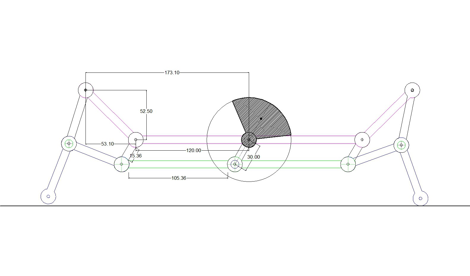
    The final walker parameter are:

    • Axle: (0.0 mm,0.0 mm)
    • Hip:  (-53.1 mm,52.5 mm)
    • Crank L1: 30.0 mm
    • Thigh L2: 60.0 mm
    • Idle    L3: 59.3 mm
    • Shin   L4: 60.0 mm
    • Knee Angle: 90.0 degrees

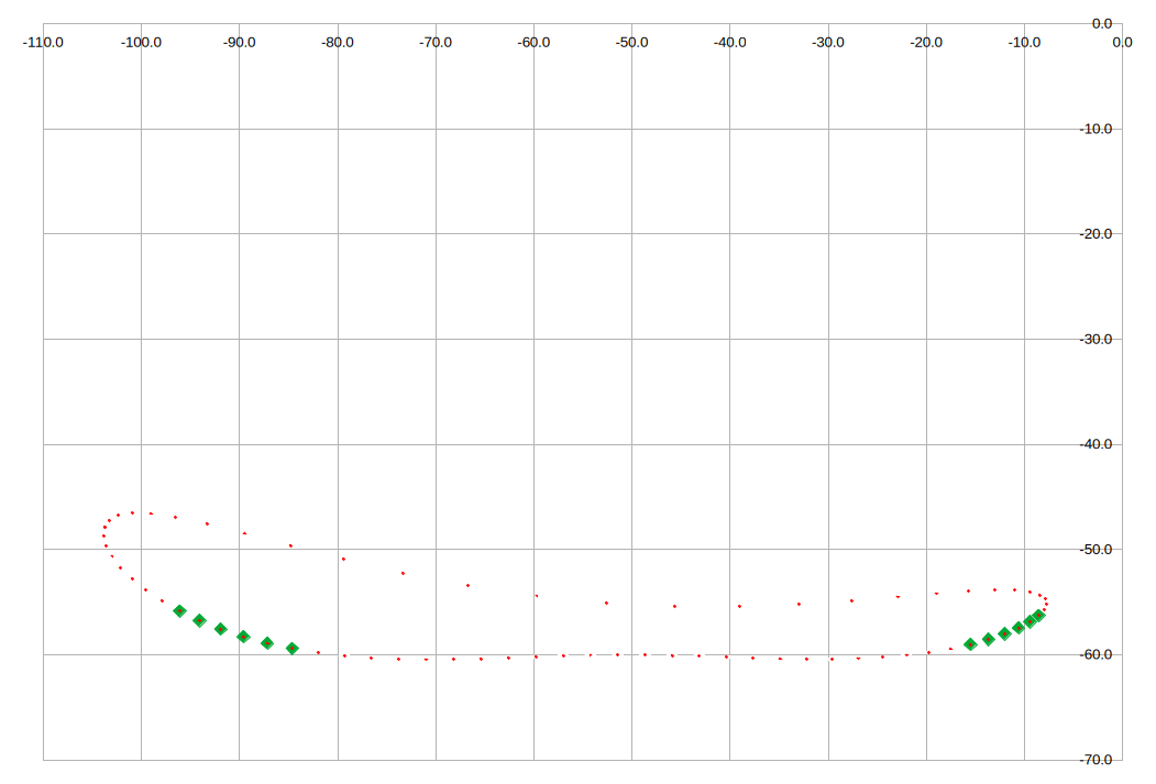
    Reducing the minimum mid-section upper and lower range to 5 mm for the final result:

    Note the flat bottom has been optimised for 120 degrees
    -

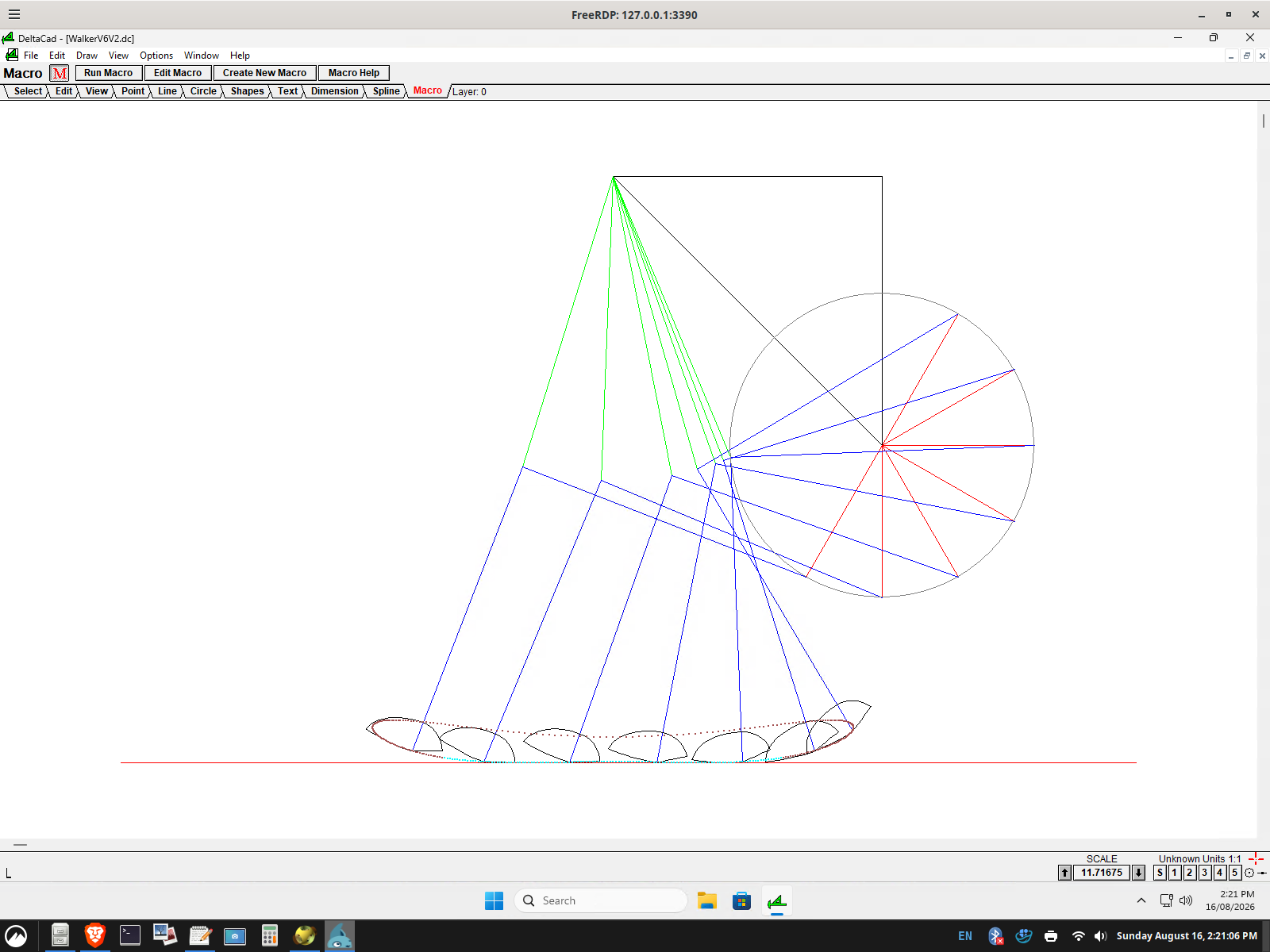
    The same design as imported into a CAD package:

    Note the cyan bottom range is for 180 degrees.

    -

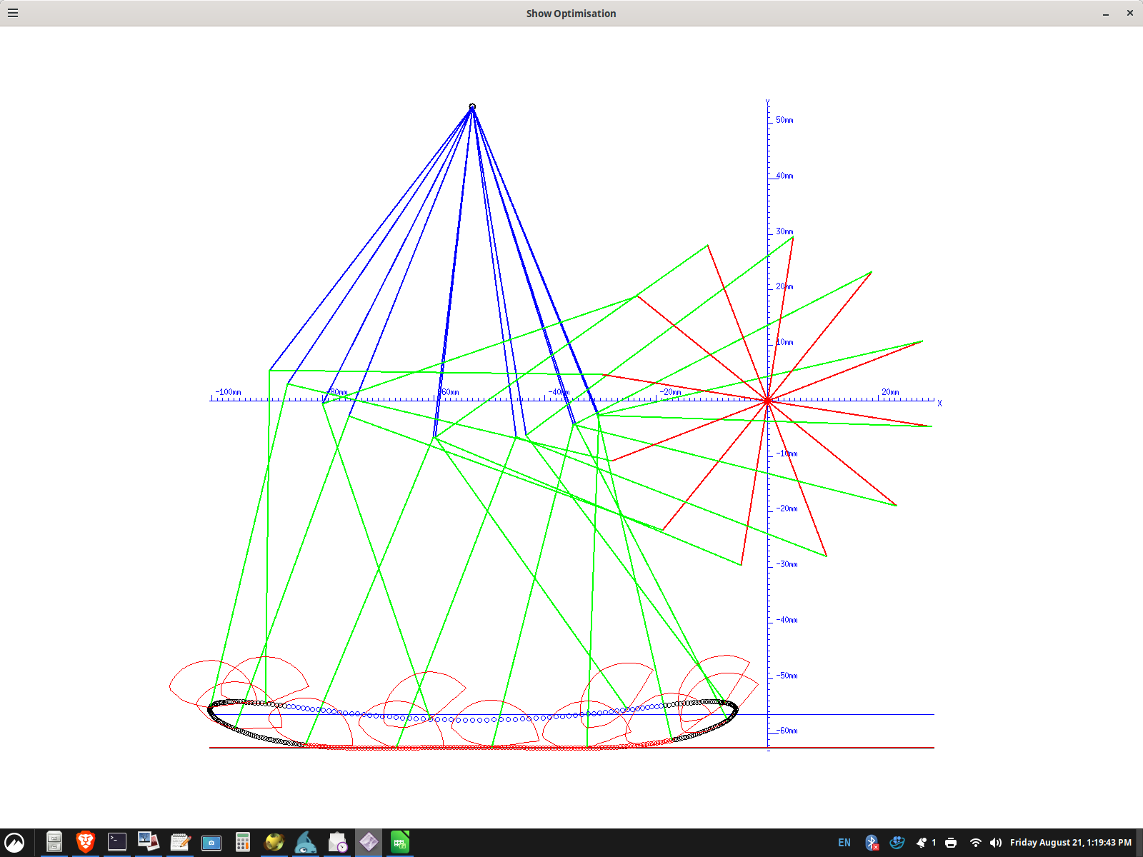
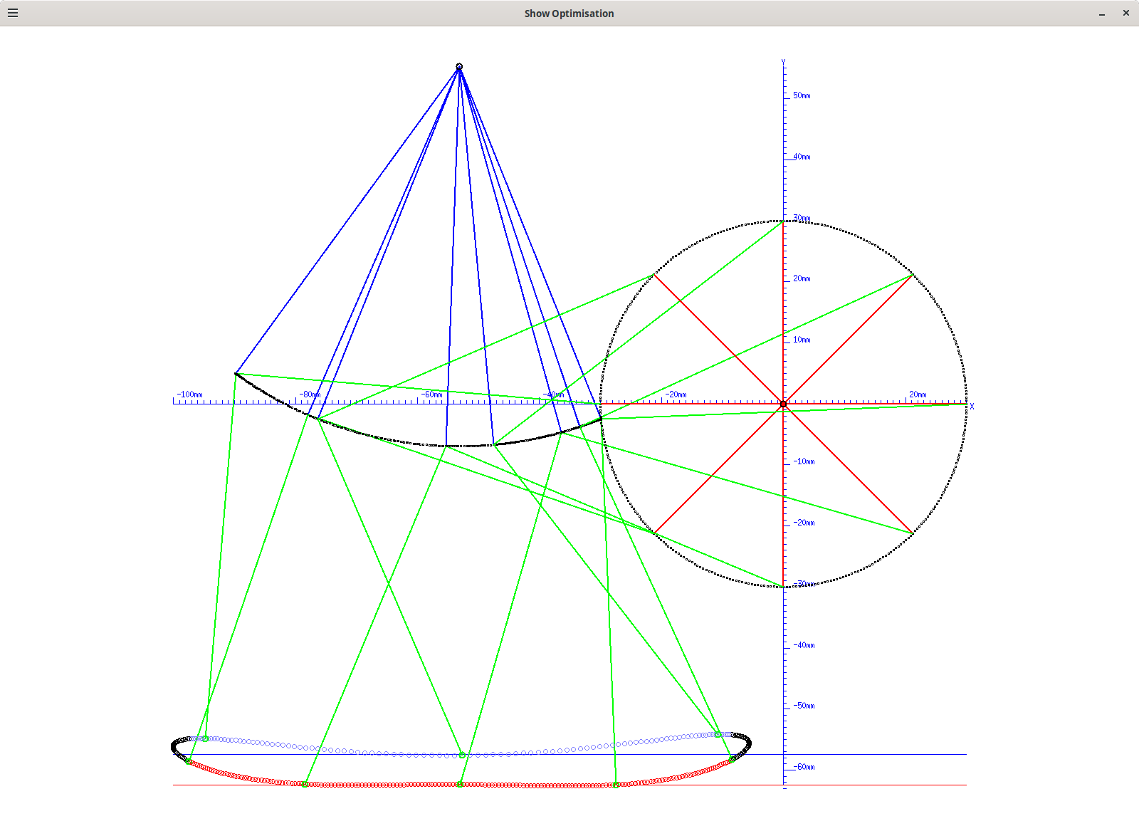
    This is what I see after my optimiser runs:

    -

    Clearly the 4 bar linkage can be used for a three foot (120 degree) walker, but its use would be best for relatively smooth floors as the minimum clearance is about 5.0 mm (for a 94 mm step).

    The cyan vertical range (for 180 degrees) is about 3.5 mm, suggesting a two foot (rather than three foot) walker is possible, but perhaps some what bumpy ride.

    AlanX

  • Modelling the 4 Bar Linkage

    agp.cooper07/22/2026 at 05:06 0 comments

    Modelling the 4 Bar Linkage

    -

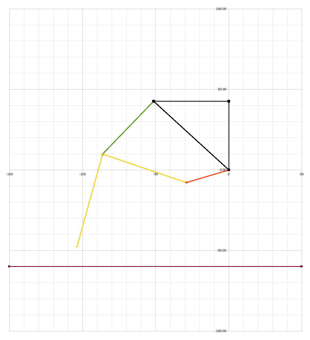
    It is convenient to build the initial model in a spreadsheet. The results can be displayed as a graph:

    -

    First steps would be to start at the Axle (0,0) on the black base plate and calculate the red crank position:

    X1 = L1*COS(RADIANS(A0))+X0
    Y1 = L1*SIN(RADIANS(A0))+Y0

    Where:

    • (X0,Y0) is the Axle position
    • A0 is the rotation angle (clockwise from the X axis)
    • L1 is the Thigh length
    • (X1,Y1) is the Crank position

    -

    Next is the find the intersection of two circles from the Crank and the Hip:

    -

    There are generally two solutions and the correct one needs to be selected. If the order of the parameters are consistent, then the selected solution will be consistent.

    -

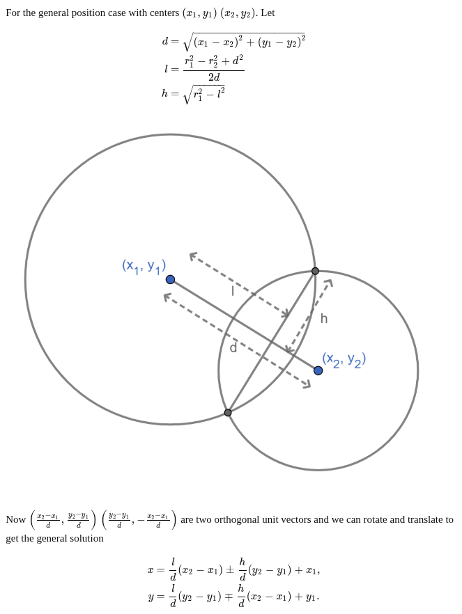
    One method to solve this problem follows:

    Source: https://math stackexchange.com/questions/256100/how-can-i-find-the-points-at-which-two-circles-intersect

    -

    Here are the Circle Intersection Calculations:

    CX1 = Crank X
    CY1 = Crank Y
    R1 = Thigh length (L2)
    CX2 = Hip X
    CY2 = Hip Y
    R2 = Idler Length (L3)
    D = SQRT((CX1-CX2)^2+(CY1-CY2)^2)
    L = (R1^2-R2^2+D^2)/2/D
    H = SQRT(R1^2-L^2)
    IX1 = L/D*(CX2-CX1)+H/D*(CY2-CY1)+CX1
    IY1 = L/D*(CY2-CY1)-H/D*(CX2-CX1)+CY1
    IX2 = L/D*(CX2-CX1)-H/D*(CY2-CY1)+CX1
    IY2 = L/D*(CY2-CY1)+H/D*(CX2-CX1)+CY1

    -

    The two solutions are:

    1. (IX1,IY1)
    2. (IX2,IY2)

    -

    For the way I ordered my circles, the solution 2 (IX2,IY2) was chosen for the Knee position:

    X2 = IX2

    Y2 = IX2

    -

    Finally the Foot has to be extended (L4) from the Knee at 90 degrees toward the Floor:

    Thigh Angle: A = DEGREES(ATAN2(X2-X1,Y2-Y1))
    Foot X: X3 = L4*COS(RADIANS(A+90))+X2
    Foot Y: Y3 = L4*SIN(RADIANS(A+90))+Y2

    Note: Spreadsheets use atan2(Cos,Sin) while C code uses atan2(Sin,Cos).

    -

    Having satisfied myself that I the equations are working, I can code the model in C code for optimisation.

    AlanX

View all 6 project logs

Enjoy this project?

Share

Discussions

Similar Projects

Does this project spark your interest?

Become a member to follow this project and never miss any updates