 Vlad
Vlad

I already knew that trying to connect it to the TV via RF had failed, so I tried using the signal before the RF modulator and feeding it into the composite video input. The result was as follows:
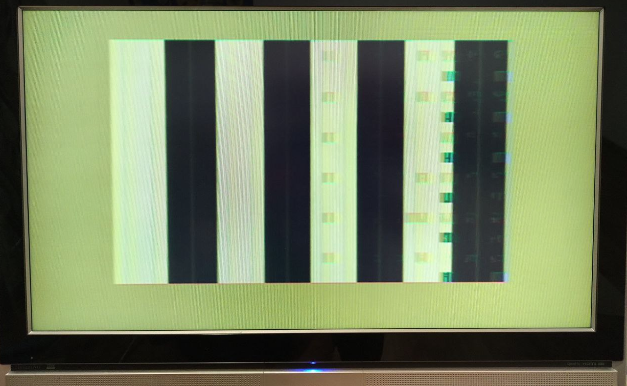
This means the ULA is reading video memory and outputting a video signal, but the processor or ROM are not working.
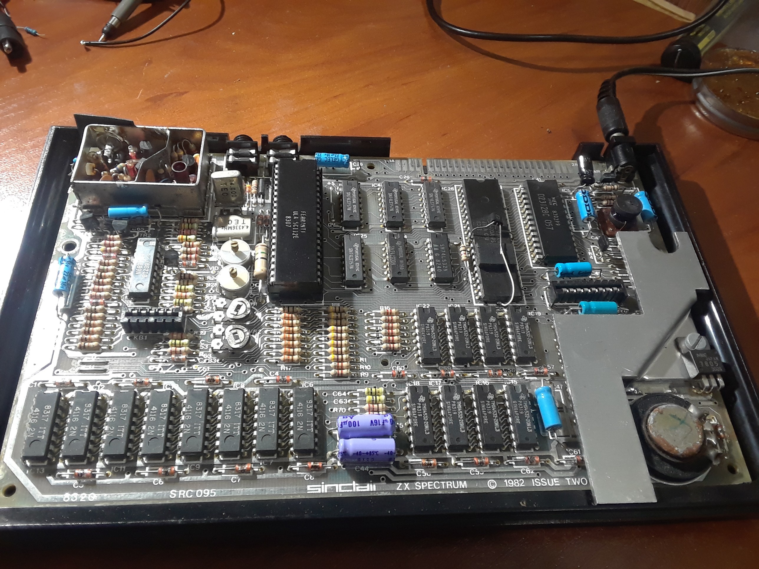
The board looked fine; we can see the "spider mod" over the processor, as well as several other improvements recommended by Sinclair in the original service manual, mostly related to the power supply:
I checked the processor pins with an oscilloscope. Some address pins were changing, but pins A14 and A15 were constantly at +1.5 V, so the ULA wasn't outputting a ROMCS signal. To make sure it wasn't a ULA issue, I installed the ULA on an additional socket, which allowed me to disconnect any ULA pin from the board and test the signals on the ULA and the board separately:
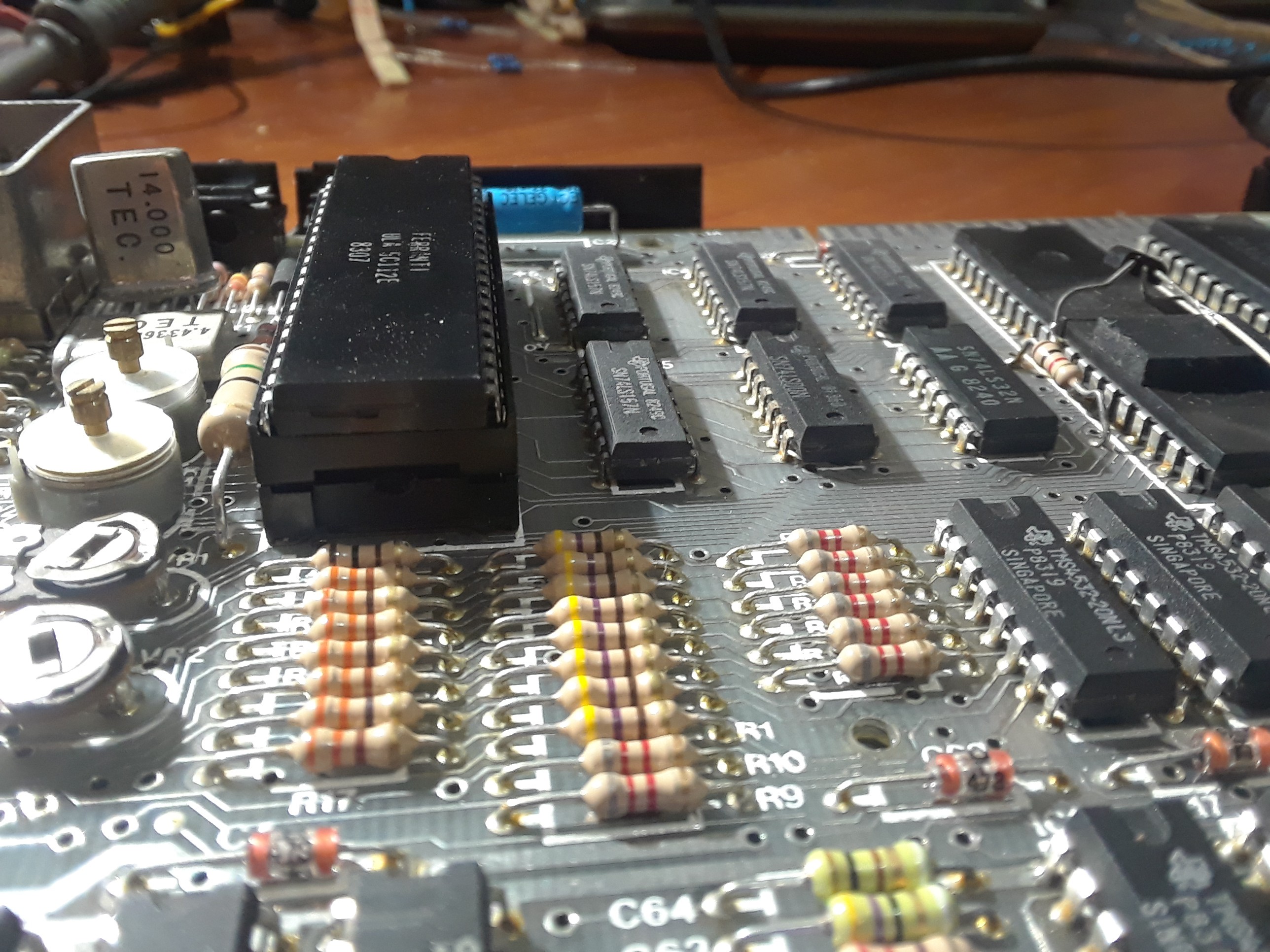
Lines A14 and A15 still had +1.5 VDC. The clock signal from the ULA was normal, and the processor still showed some activity.
While I was checking everything with an oscilloscope here and there, something changed. The processor stopped working; it was dead and cold. I don't know what happened, and I don't know if my actions were the cause.
In any case, the processor is definitely dead now, so I decided to connect another processor in parallel using an edge connector and see what happens:
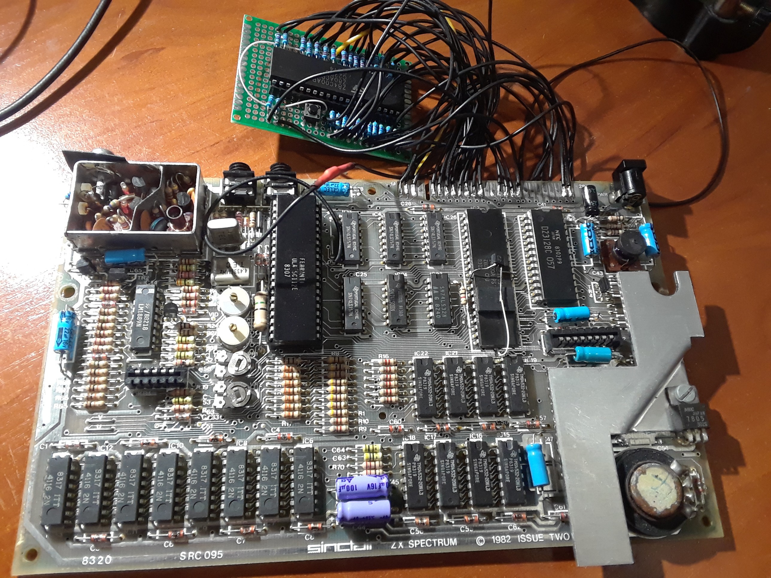
Now the video was a bit different:
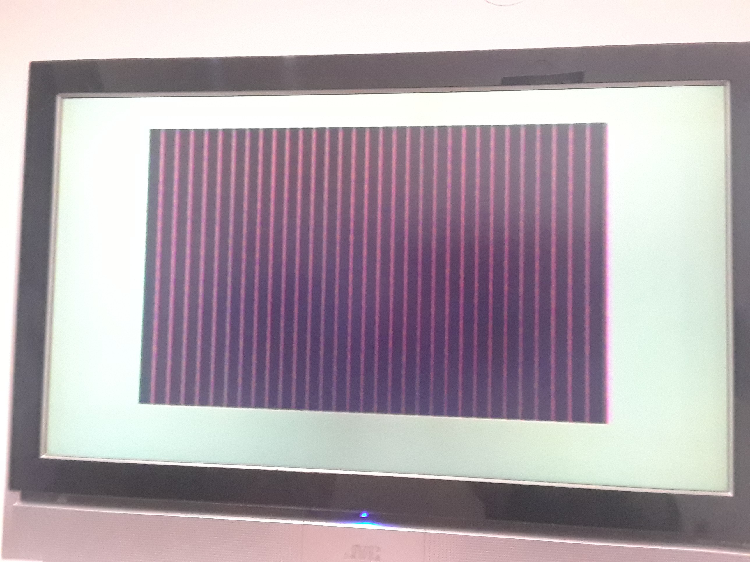
It appears to be an incomplete memory check during the Spectrum's normal power-on initialization. I checked the data bus and found the cause::
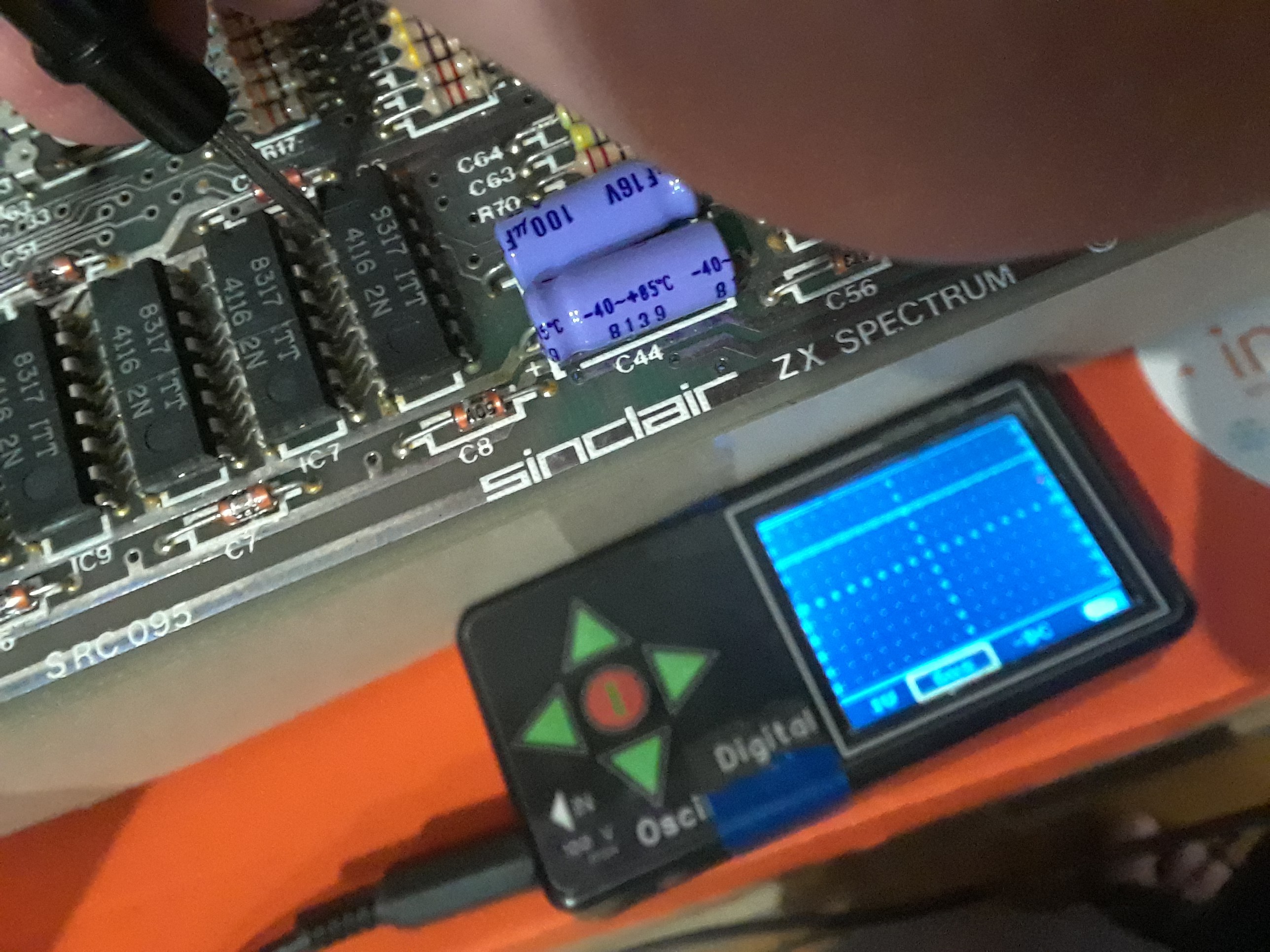
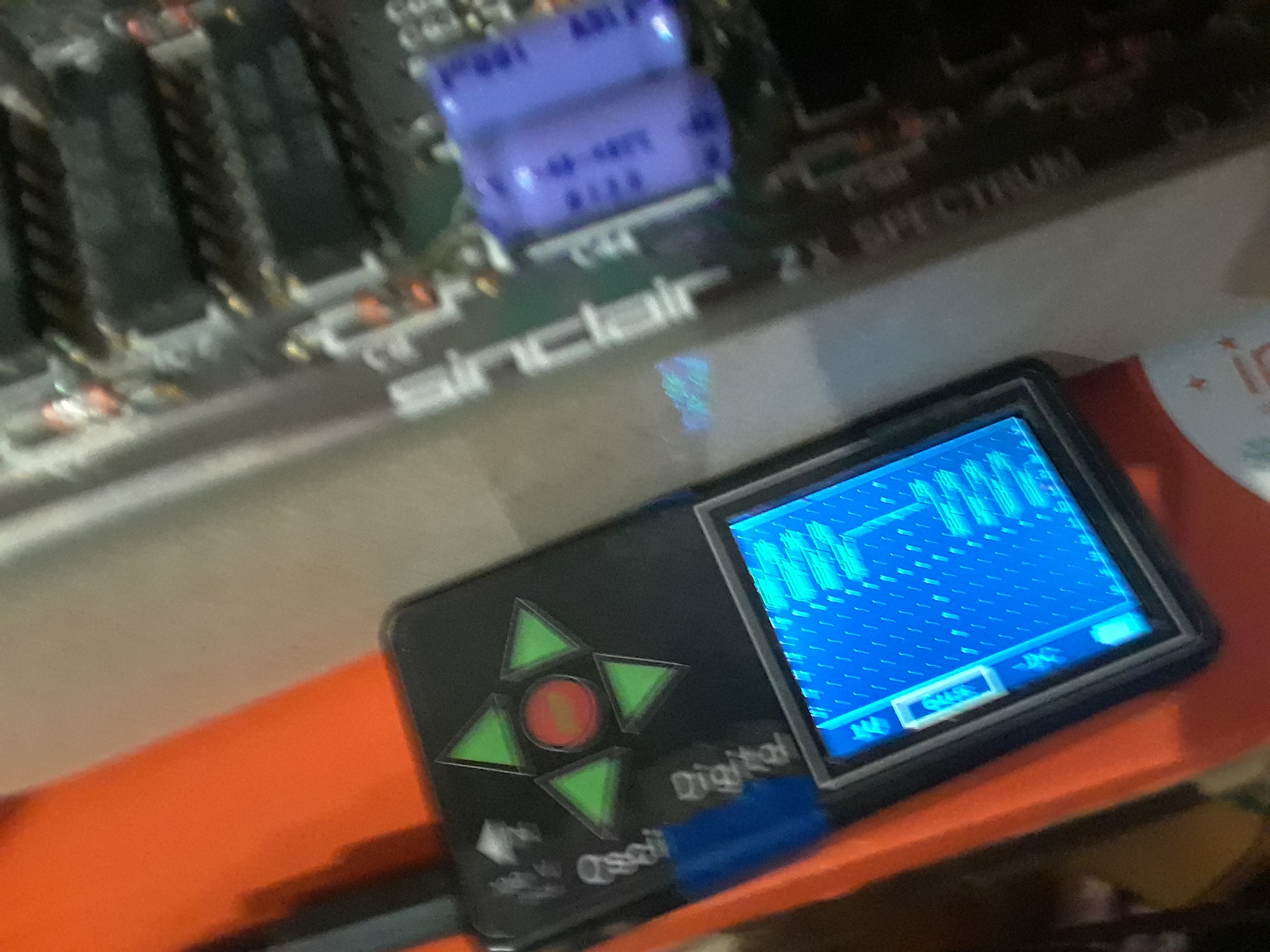
This memory chip is dead and it's data pin is always high. Other memory chips are ok, i.e.:
So, I've replaced bad memory chip:
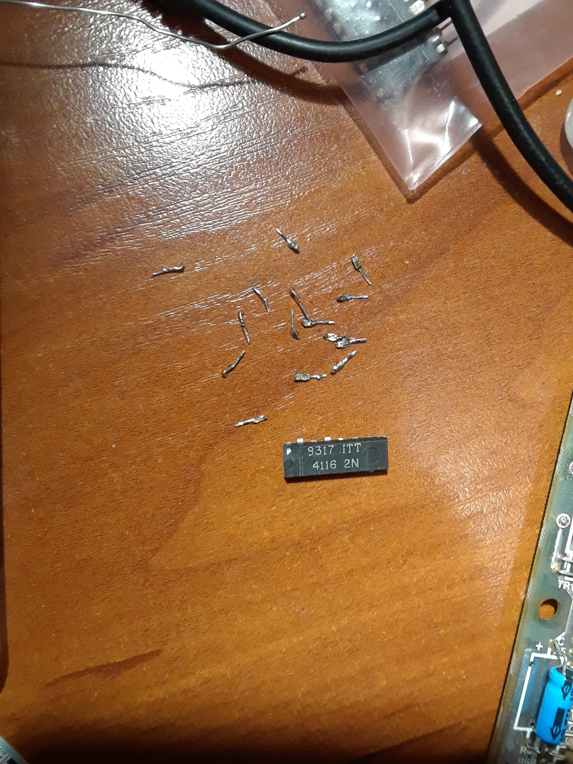
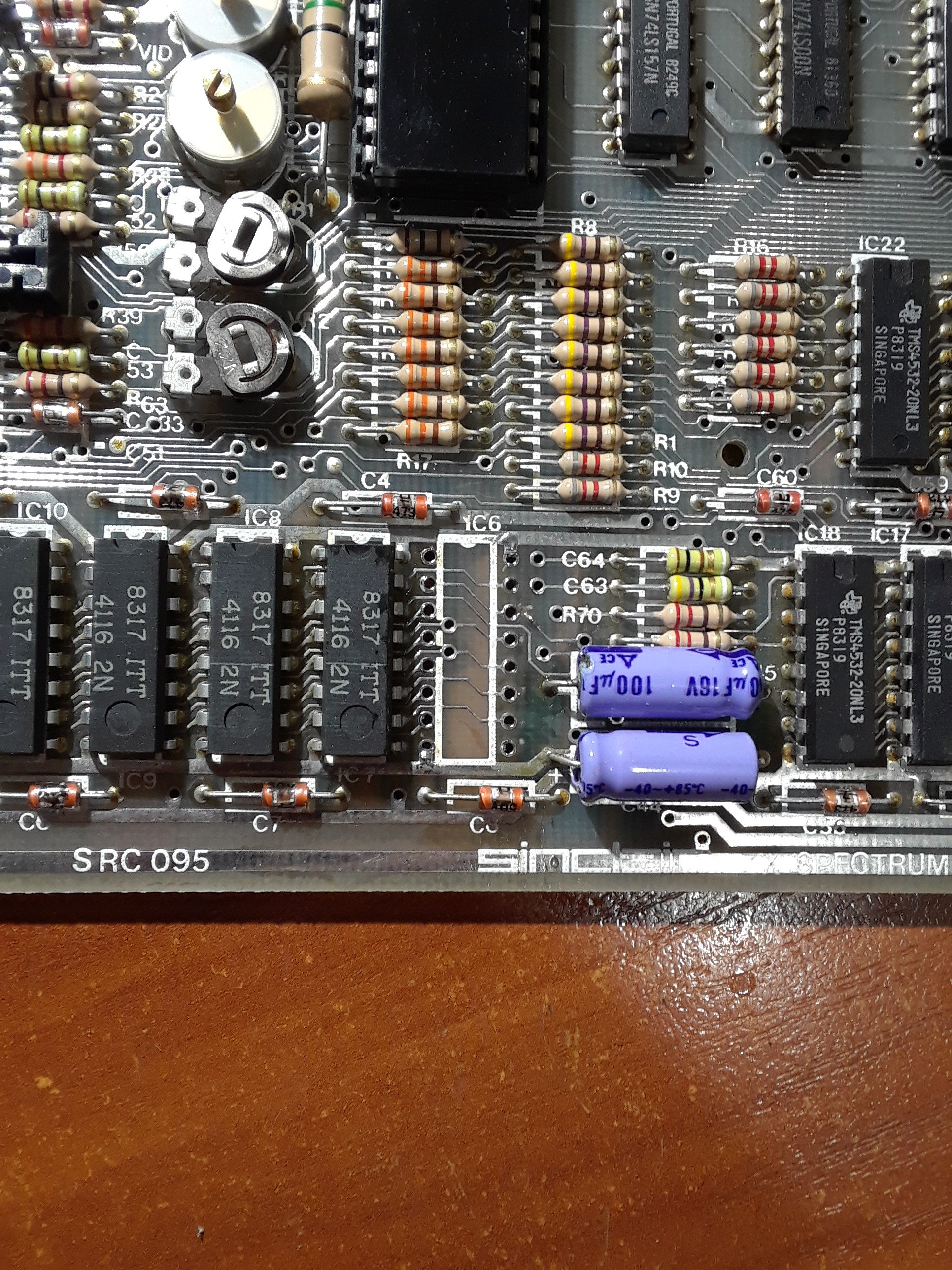
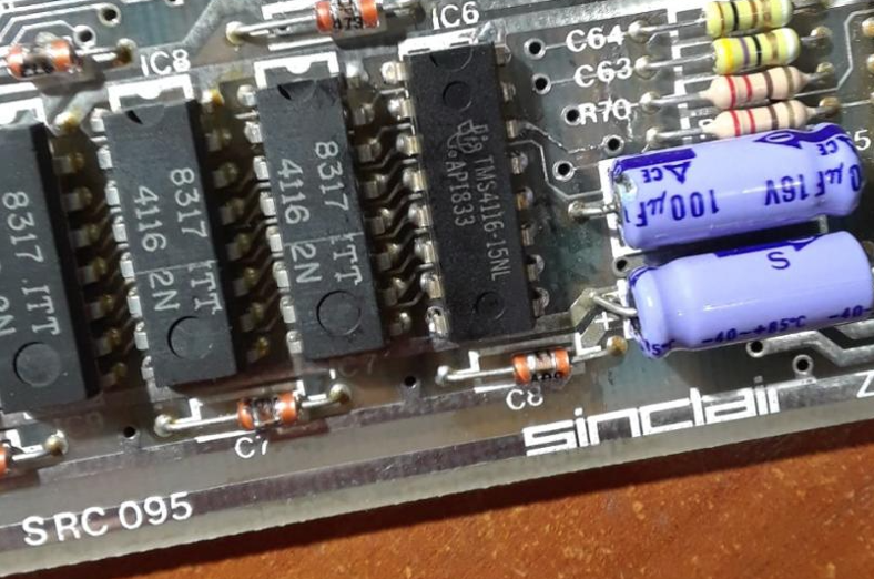
.... and CPU:
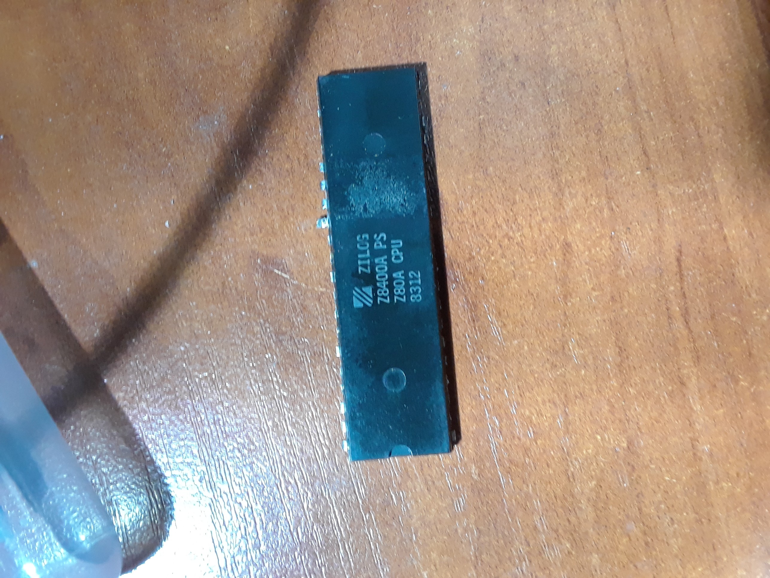
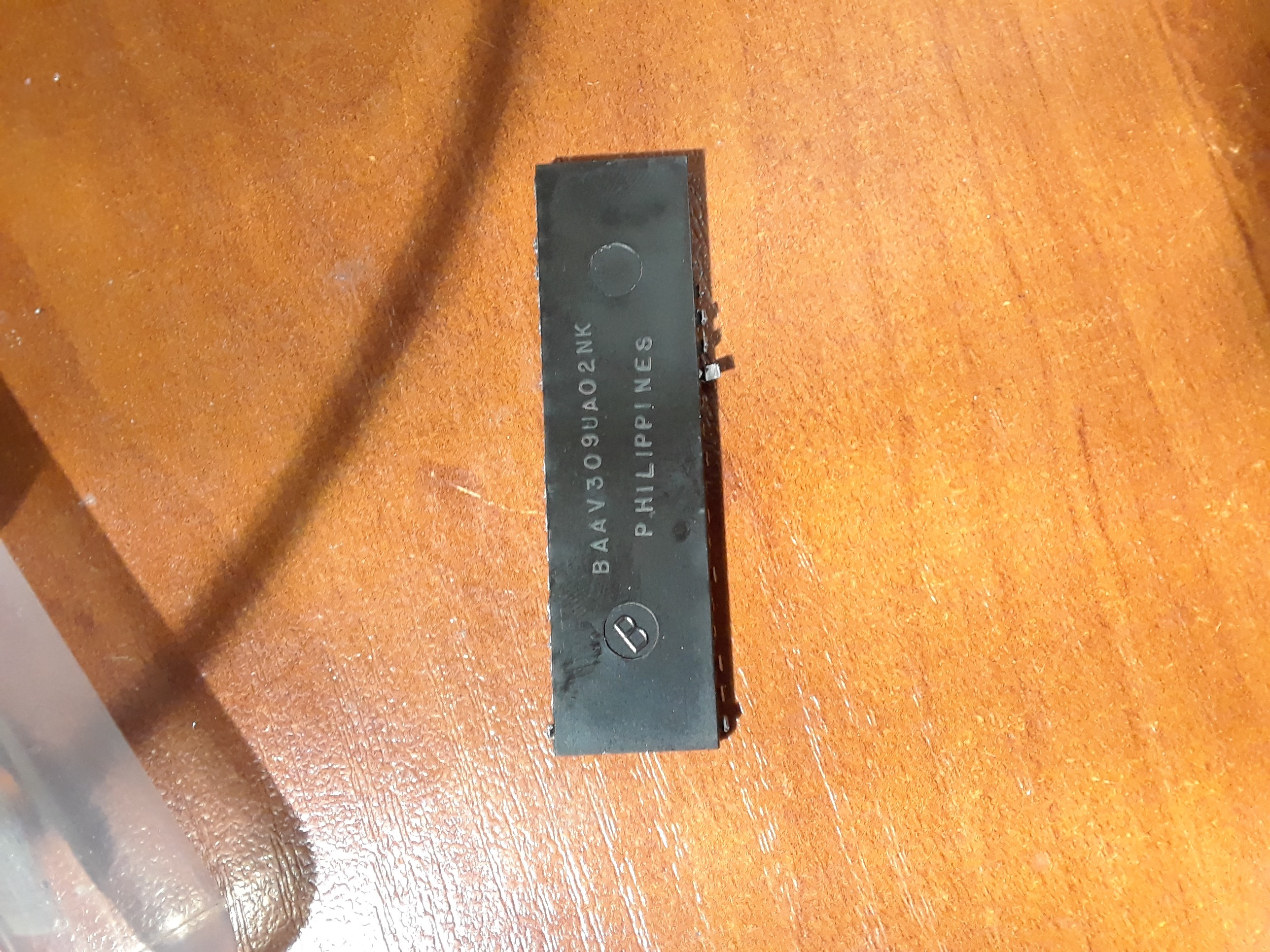
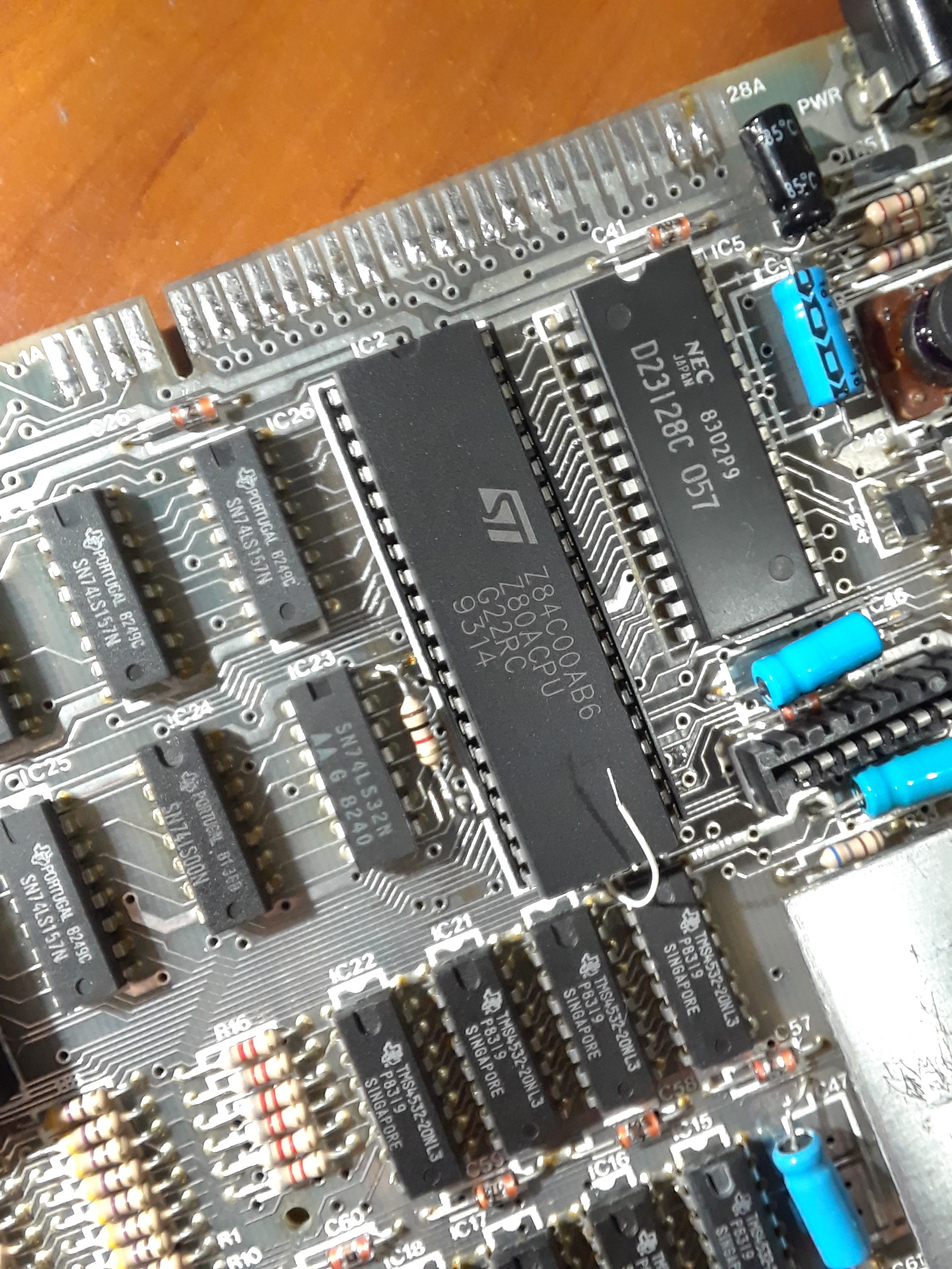
It would be probably better to replace all the memory chips...
But when I turned it On, it worked!
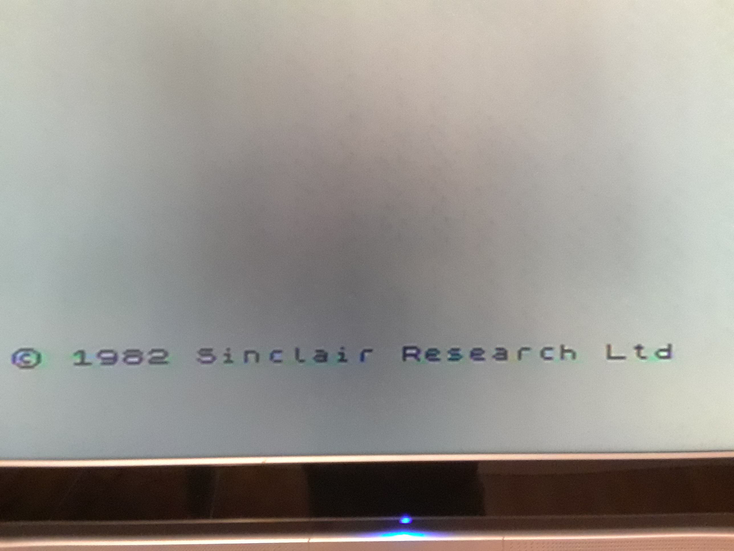
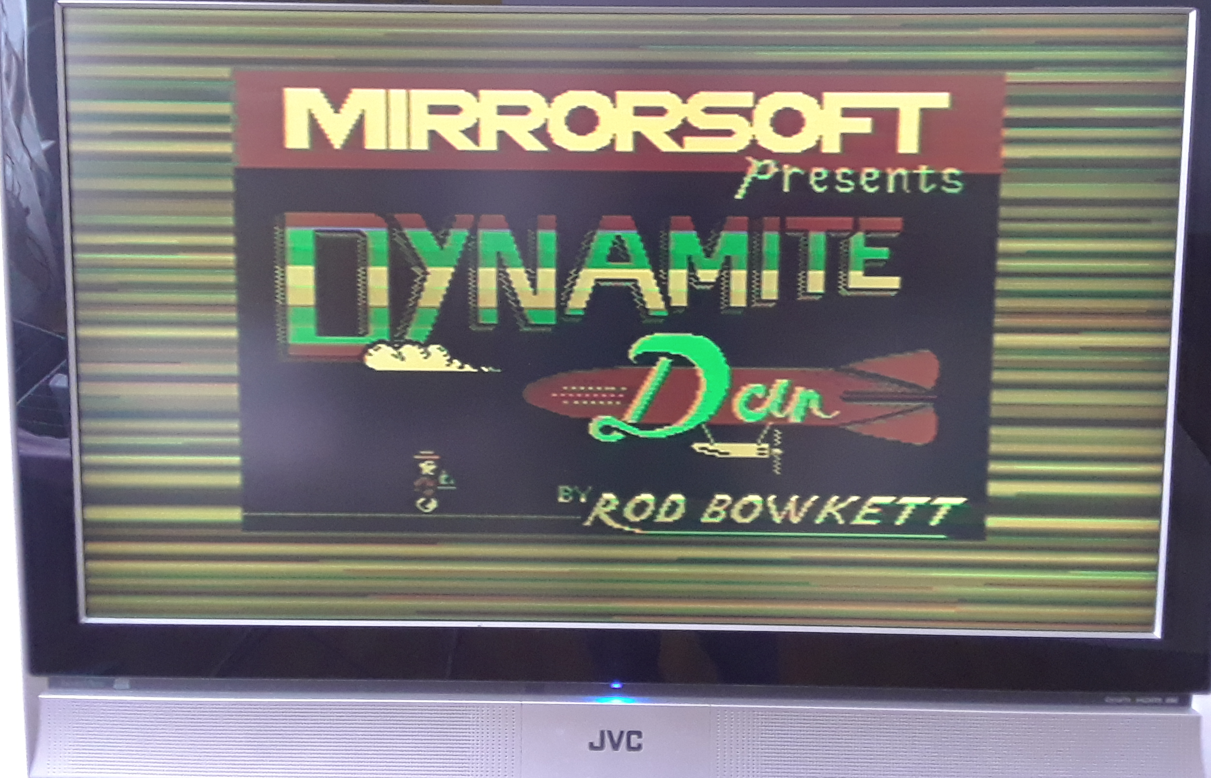
It was somewhat of a miracle to see this logo again after more than 35 years...
However, the image brightness and overall quality were poor, so I continued working on it.
A source of the video signals Y, U and V is ULA and service manual described the signals properties quite clearly, especially Y:
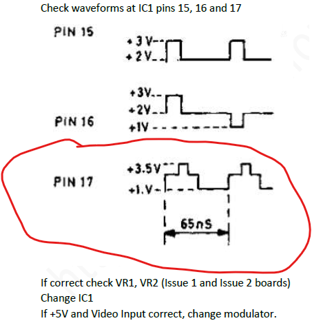
In reality, things were much worse:
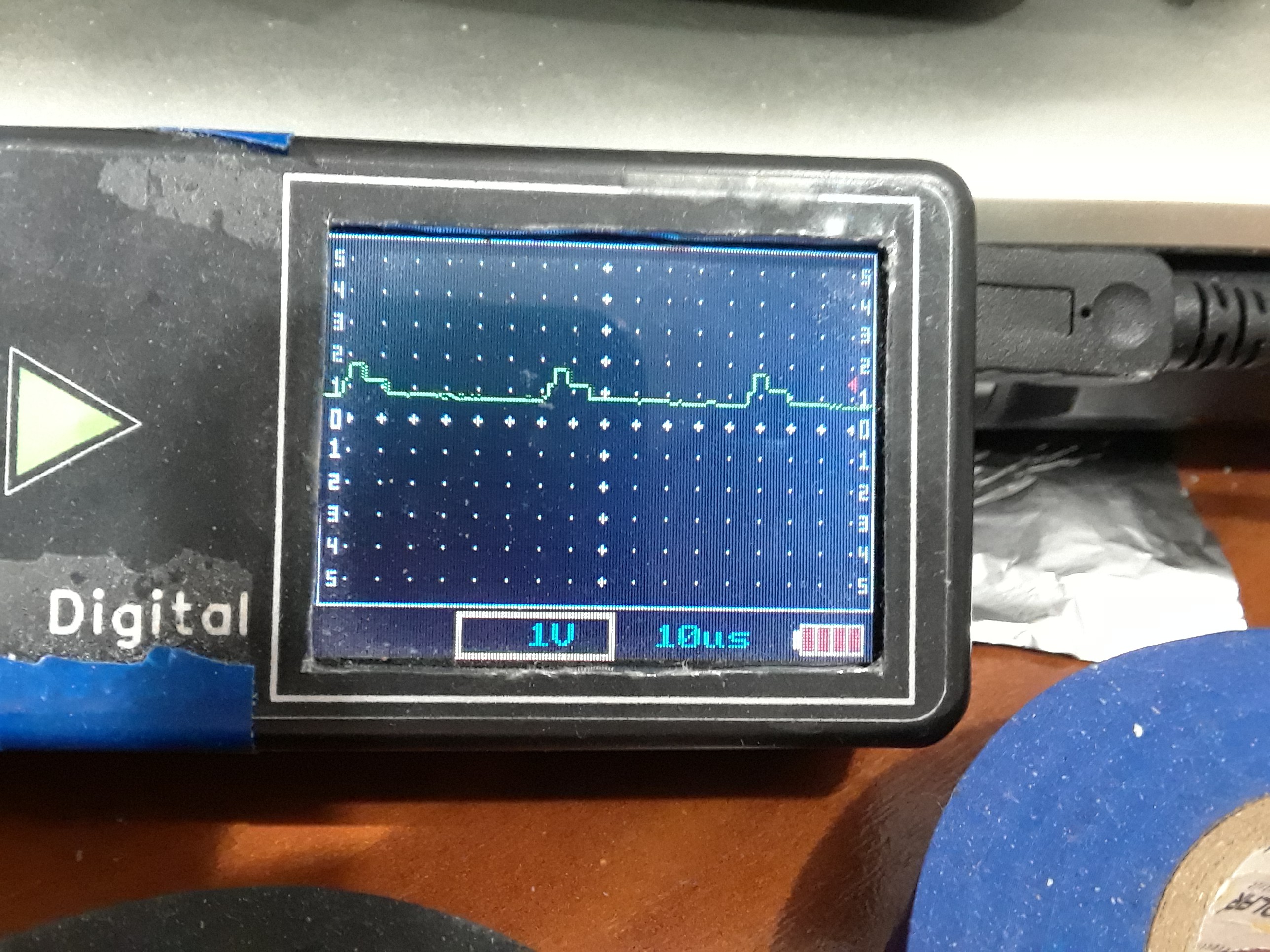
"Change IC1" was the best option but IC1 is ULA and I didn't have the spare one :)
I don't know why the ULA Y output is so poor. Probably the chip is worn out because of its age...
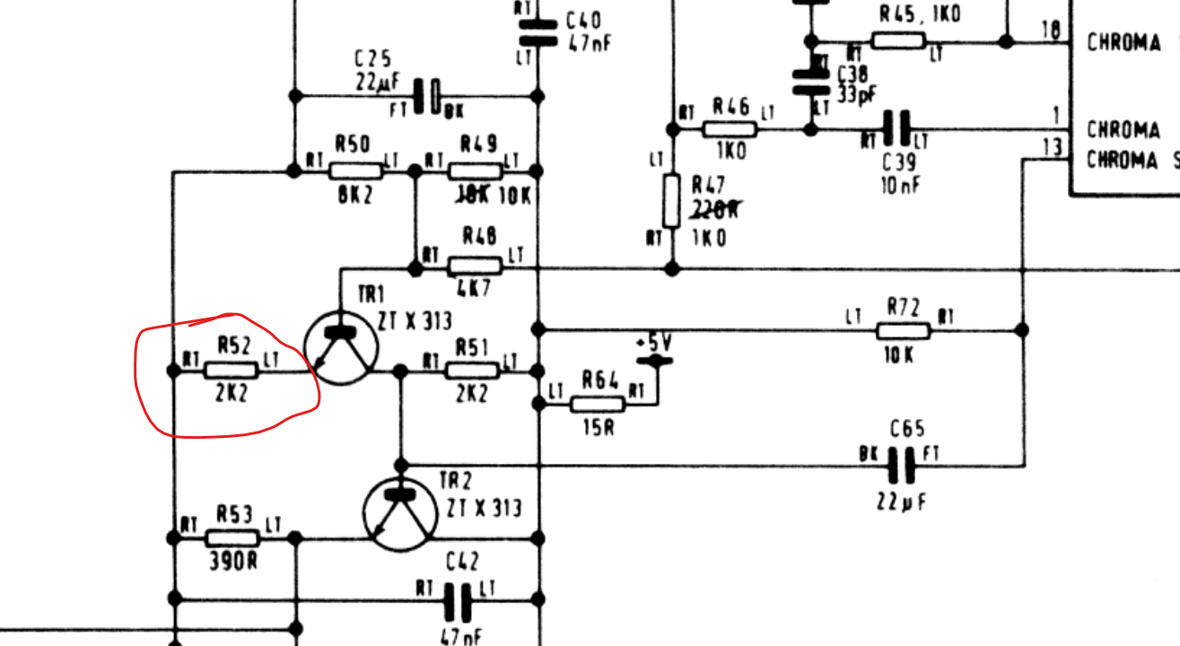
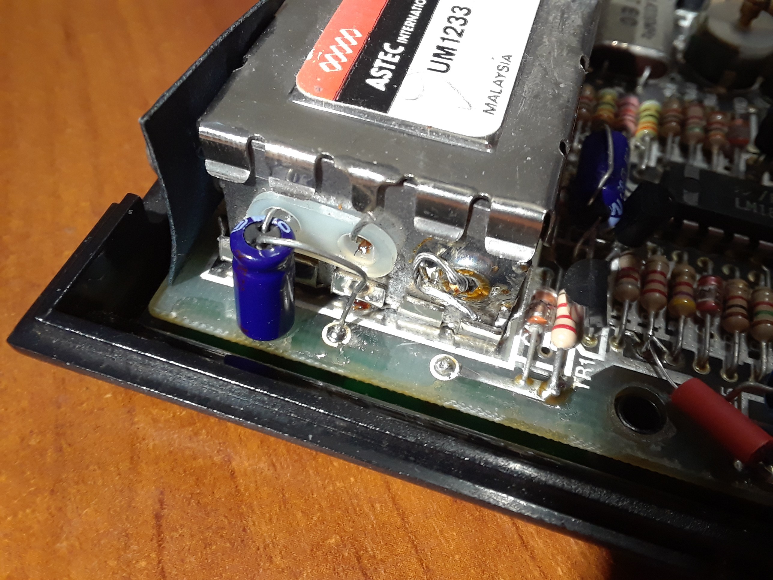
Anyway, I had to do something with this. Looking at the circuit diagram, there is some kind of a mixer and then an emitter follower for the composite video signal right before RF modulator. Resistor R52 seems to be responsible for the output voltage Vp-p so I put a similar one in parallel to decrease its resistance and increase the peak-to-peak voltage accordingly:
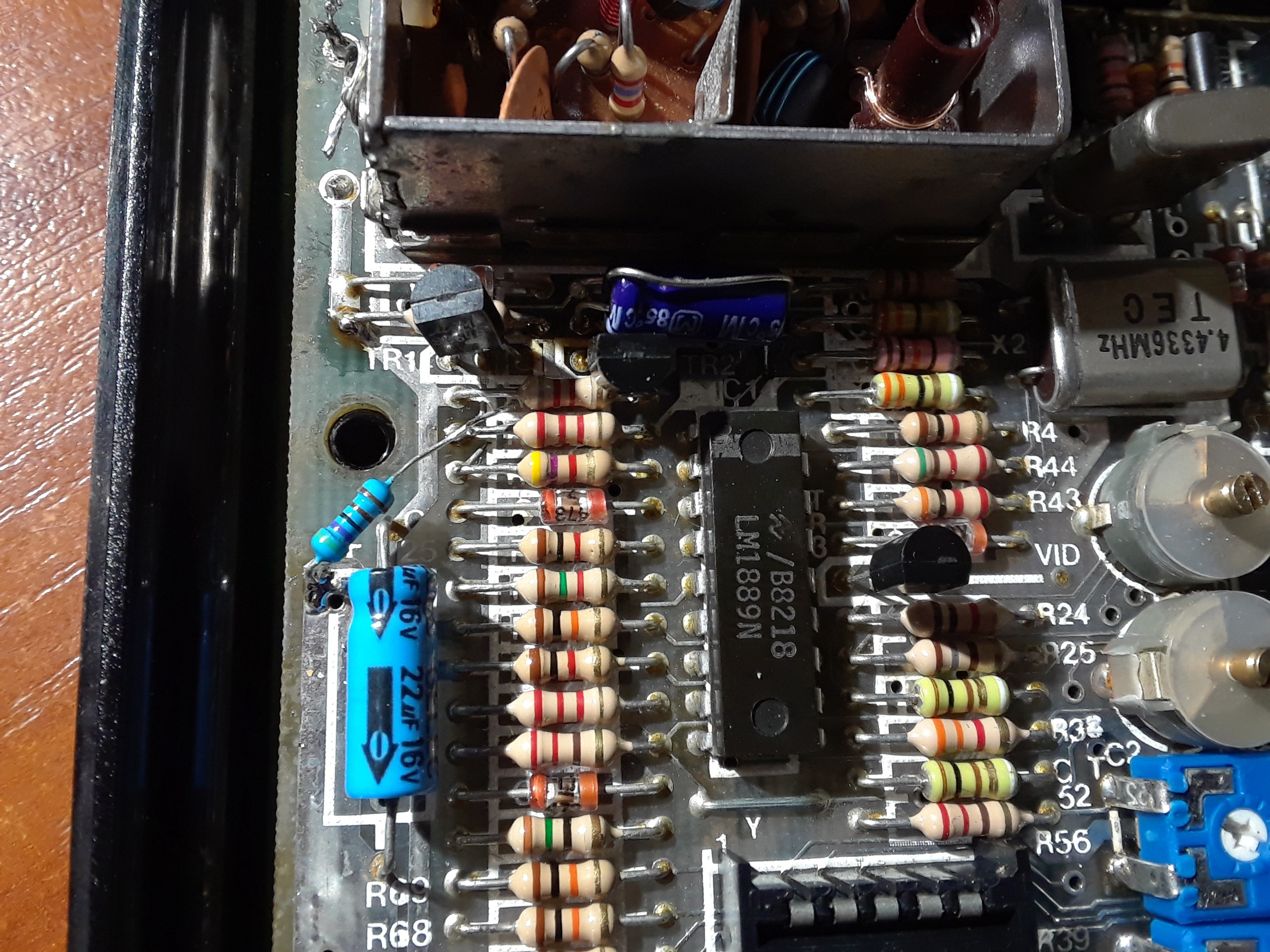
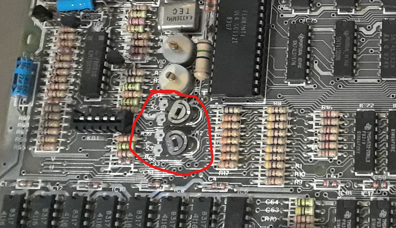
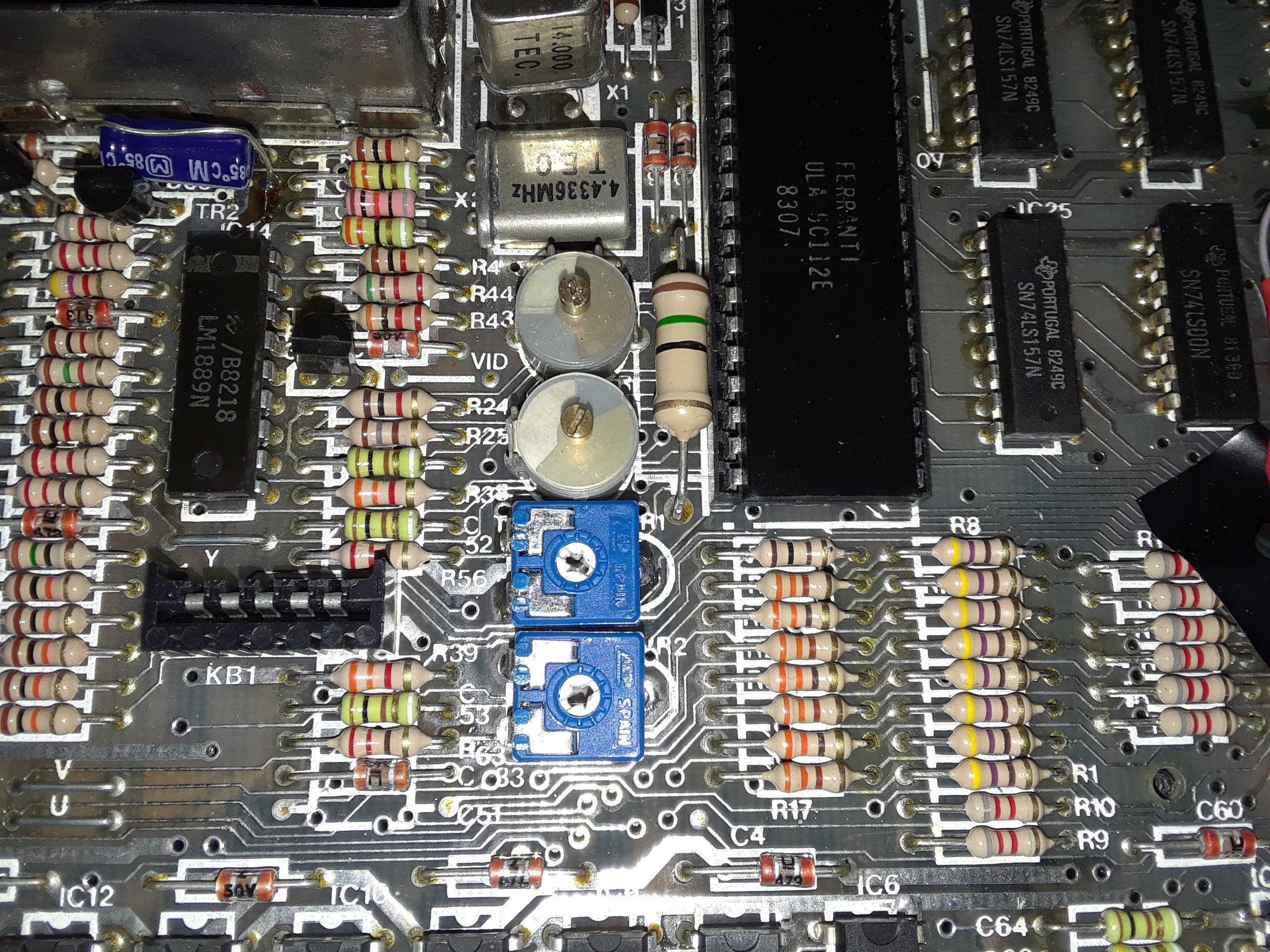
I also replaced capacitor C65 just in case, but I don't think it made any difference. Another change, which you can see in the picture, was VR1 and VR2, because the originals were unstable:
Finally, a very known "video mod" which is a capacitor at video output to TV:
As a result, the picture on the TV is much better:
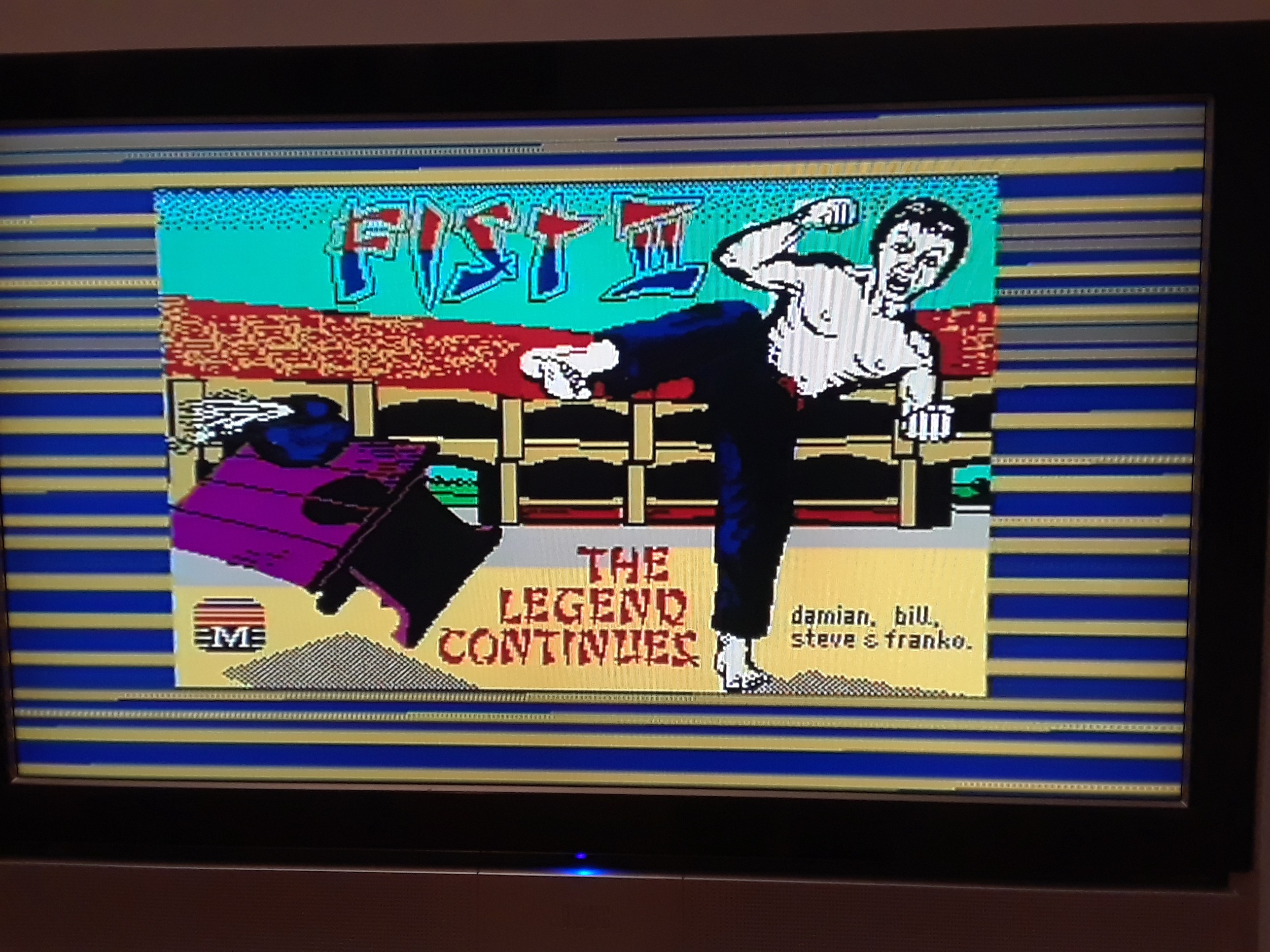
Well, this photo was taken after the refurbishing was completed...
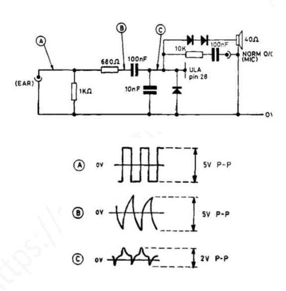
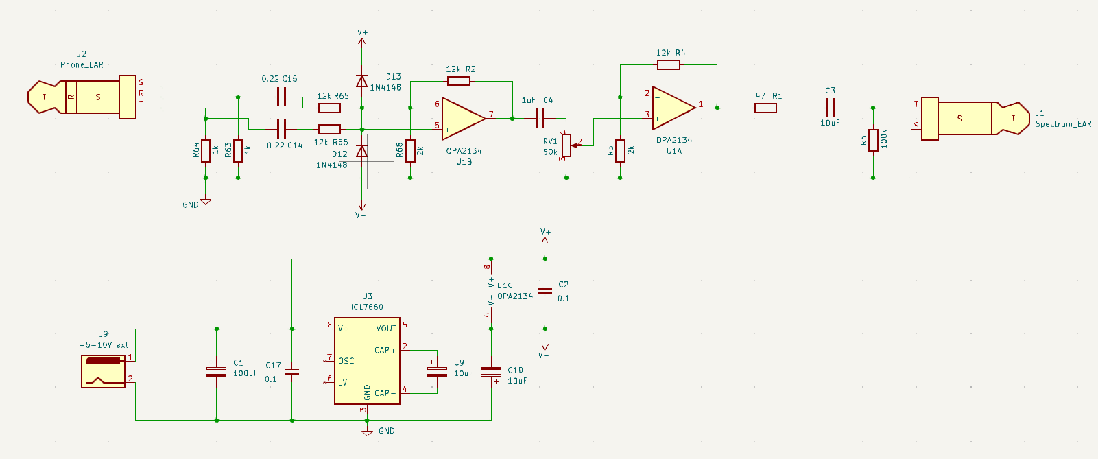
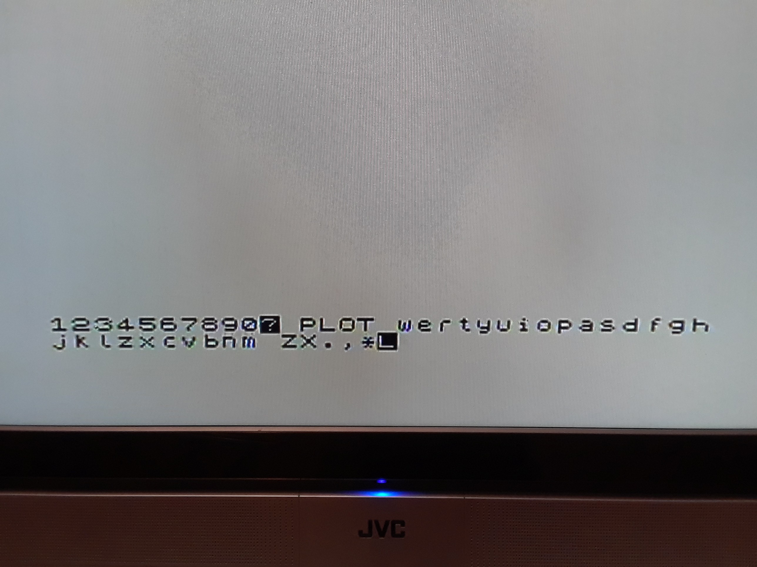
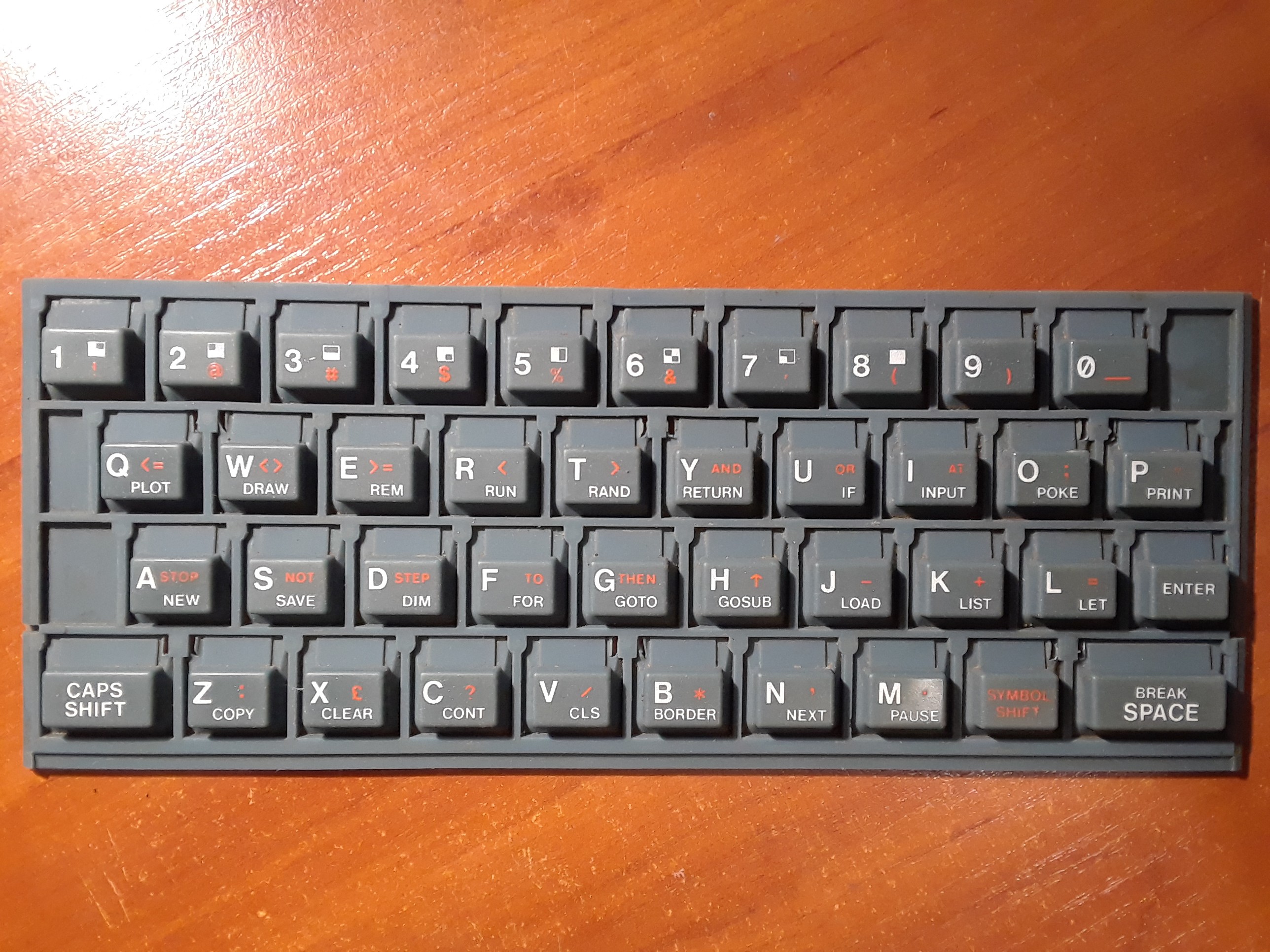
At this stage, I still had to test the cassette interface, sound, and keyboard. I'll describe this in the project logs.

 David Levi
 danjovic
 kyokohunter
 Nathan Kiesman