 Ahmet
Ahmet

What this is
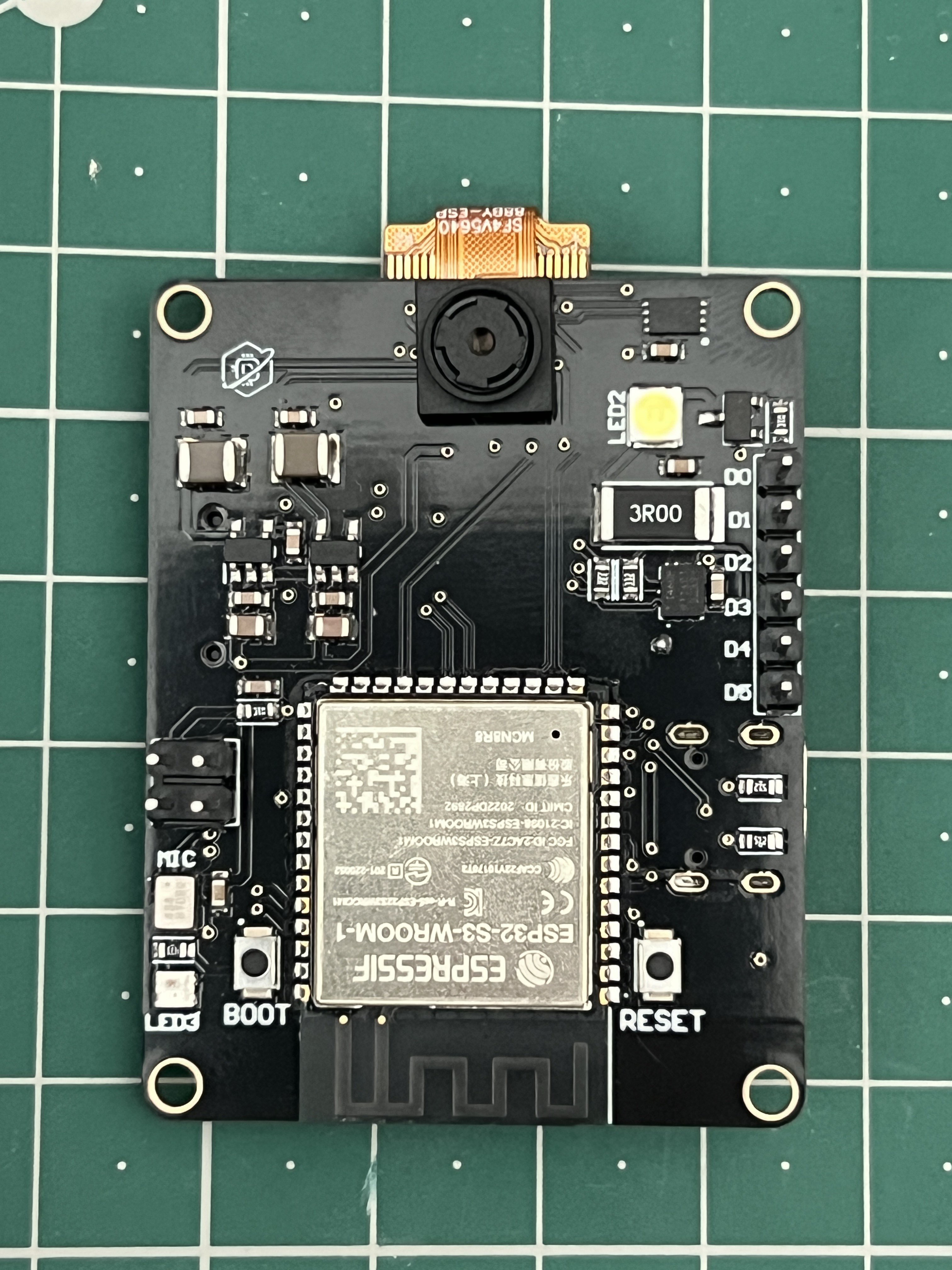
An ESP32-S3 board that runs a 5 MP camera, a 6-axis IMU, an I2S microphone and a microSD card at the same time, and hands the results to a host controller over I2C or UART.
That last sentence is the whole design brief. It is not meant to be your main controller. It is meant to be the thing your main controller asks "is there a red object, and where is it."
Why it exists
If you want vision on a small robot today, the usual answer is one of the cheap ESP32-S3 camera boards. They work, they cost almost nothing, and for a lot of projects that is the correct choice. I will say that plainly because it is true.
Where they start to hurt is when you want more than the camera. Add an IMU and you are wiring a breakout. Add a microphone and you are fighting for pins. Add an SD card and something stops working. The parts are all cheap and available. Getting them to coexist on one ESP32-S3, with a camera already consuming most of the GPIO, is the actual problem.
It works either way. Connect it via I2C or UART to a Raspberry Pi, RP2040, STM32, or any other host computer, and let it handle image processing, IMU, recording to an SD card, and audio capture via the microphone while the host computer takes care of everything else. Alternatively, since the S3 has its own radio module and doesn’t require a host computer at all, you can run it over Wi-Fi or as a standalone camera node on the device itself, using all its features simultaneously.
However, this device is not a robot’s main controller. It has no GPIO header or motor driver; the only connector available to the user is the Qwiic I2C port. This device is designed to be placed alongside another device, not to replace it.
Three revisions, and the first one was posted here to be taken apart
About a year ago I published the first prototype on r/esp32. Two criticisms came back repeatedly:
microSD placement. The socket was somewhere that made the card awkward to reach and fought for space with everything around it.
The antenna keep-out under the WROOM module. This was the serious one.
The ESP32-S3-WROOM-1 has its antenna printed into the module. Espressif specifies a keep-out region underneath and around it — no copper, no ground plane, no traces, no components — and the antenna end is supposed to overhang the edge of the carrier board. Put a ground plane under there and the antenna detunes and range collapses. The first revision did not respect that properly.
Both drove revision two. The keep-out fix is not a patch you apply later. It changes where everything else on the board is allowed to sit, so it forced a re-plan of the whole layout.
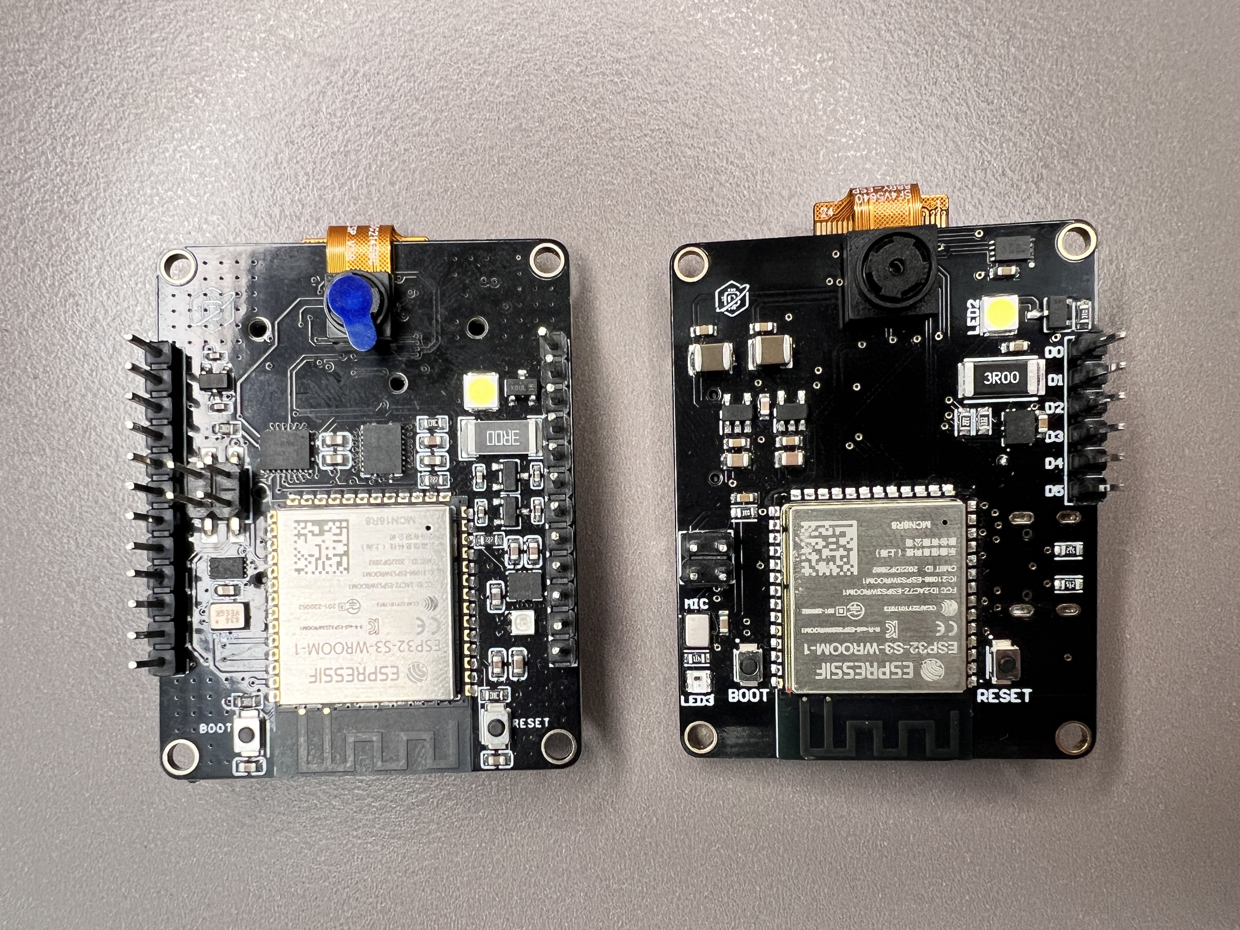
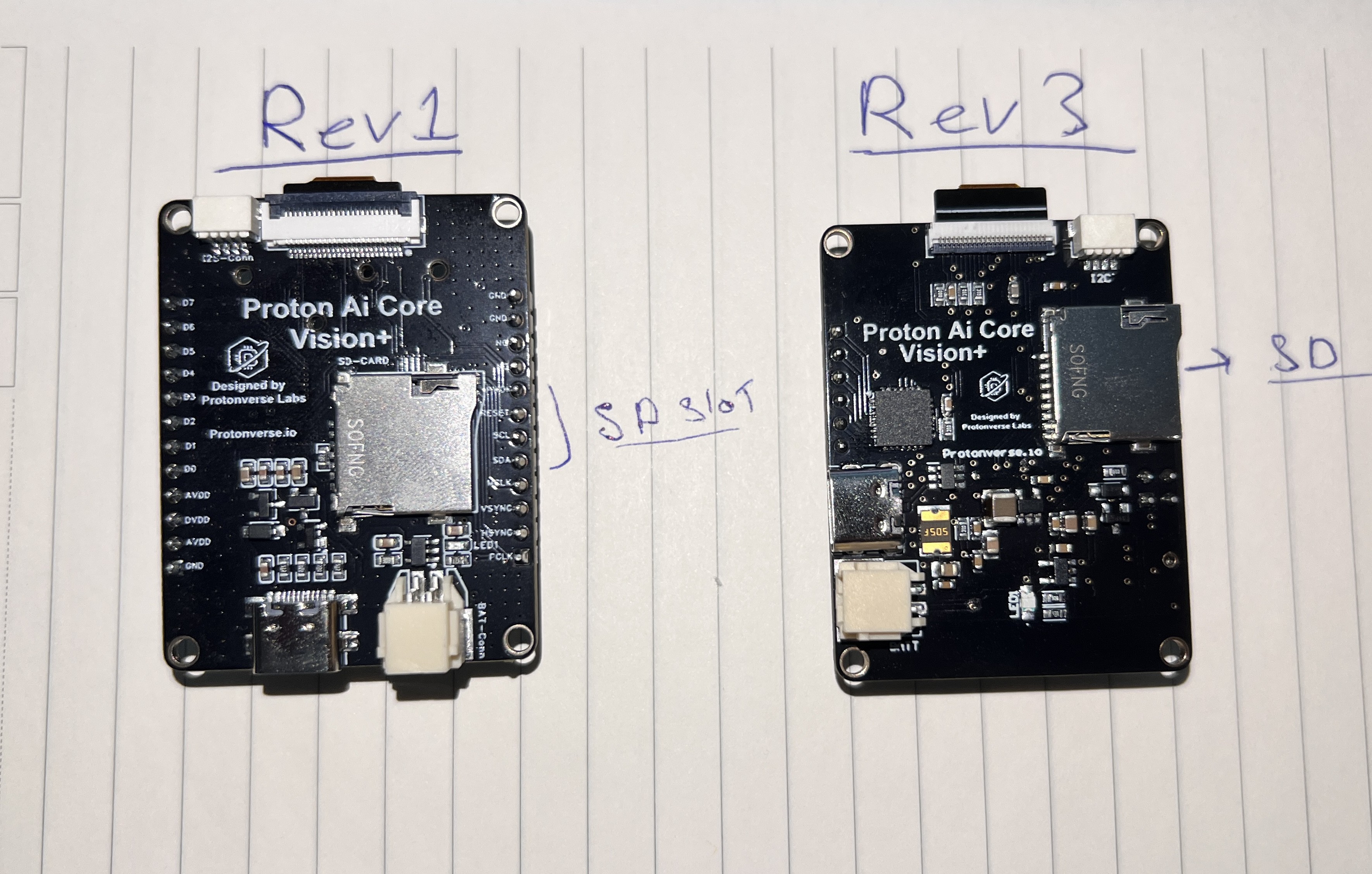
Revision three is the first one where all the peripherals run simultaneously. That sounds like a low bar. It was most of the work.
Hardware
ESP32-S3-WROOM-1-N16R8 — 16 MB flash, 8 MB octal PSRAM. The PSRAM is not optional here. A 5 MP frame does not fit anywhere else, and octal was chosen over quad for bandwidth. The cost of that choice is real: octal PSRAM consumes GPIO35, 36 and 37, which you do not get back.
OV5640, 5 MP, on an FPC. Connected over the parallel DVP interface. This is the single largest consumer of pins on the board.
ICM-42670-P — 6-axis IMU. This is the part that is genuinely hard to find already on a camera board at this size. If the board is going on a robot, knowing how it is oriented while it is looking at something is worth more than it sounds.
ICS-43434 — I2S MEMS microphone. Input only. There is no audio output on this board and there never was — the brief was vision, and audio out did not belong in it.
microSD — for logging frames and captured datasets locally. Loading ESP-DL models from the card rather than baking them into firmware is something I'm working on now. The point is that swappinga model shouldn't mean reflashing the board particularly in a classroom, where a teacher on r/esp32 described spending an hour getting students through capture, annotation...
Read more »
 Thermal Tool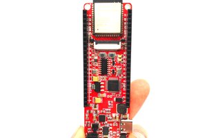
 allexoK
 Ryan Bailey
 Blade Master